Page is loading ...

windynation
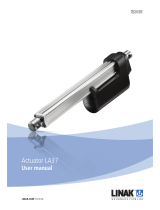
LIN-ACT1-XX Linear Actuators
SPECIFICATION
LIN-ACT1-02
LIN-ACT1-04
LIN-ACT1-06
LIN-ACT1-08
LIN-ACT1-12
LIN-ACT1-16
LIN-ACT1-20
LIN-ACT1-30
Stroke Length
2” (51mm)
4” (102mm)
6” (152mm)
8” (203mm)
12” (305mm)
16” (406mm)
20” (508mm)
30” (762mm)
Rated Load
225 lbs (900N)
Travel Speed
(Max)
0.39 in/sec (10 mm/sec)
Rated Voltage
12 VDC
Current Draw
(Max)
< 2.5 A
Install Dimension
(Min)
Stroke Length + 4.33” (110mm)
Mounting Holes
0.31” (8mm)
Limit Switches
Fixed Inner (not adjustable)
Operating Temp
-14.8oF to +149oF (-26oC to +65oC)
Protection Class
IP65
Duty Cycle
25%
Noise Level
< 50dB
INSTALLATION
WARNINGS: 1.The total load on the actuator (structure weight, structure friction, and possible actuator friction) must be less than or
equal to the rated load of actuator.
2. The moving load must be centered above the actuator extension tube so that actuator lifting point is located at the
center-of-mass of the structure. Unless the structural design is properly braced, off-centered loads will cause additional
friction that can (1) exceed the rated load of the actuator or (2) cause the actuator shaft to bend and permanently fail.
3. Do not exceed the 25% duty cycle of the actuator: If the actuator is used at full load for 2.5 minutes, then it must
remain off for 7.5 minutes. Exceeding the duty cycle will cause the actuator motor to overheat and permanently fail.
1. Mount the actuator by securing the top and bottom mounting holes to two fixed positions. The stroke length of the actuator
(e.g. 12 inches) and the limitations of the particular application will determine the location of the fixed mounting positions.
IMPORTANT: Confirm that up/down movement of the actuator is smooth and within the actuators stroke length after
installation.
2. Secure the top and bottom mounting holes of the linear actuator onto the two mounting fixtures using 5/16” diameter bolts.
windynation Page 1 of 2

Actuator User Manual Revision 3.0
3. Connect the red wire to the positive post and the black wire to the negative post of a 12 volt DC power supply.
4. The operation of the linear actuator should be tested manually after the installation is completed.
Users should use caution to ensure that:
• The travel distance of the actuator satisfies the requirement of the structural design.
• The extended and retracted limit switches operate normally (The limit switches should stop the motor when the extension
tube is fully retracted or fully extended)
• If the motor runs too slow or does not give full force, (1) the power supply is insufficient and needs to be increased or (2)
the load being applied to the actuator is too great and needs to be reduced to less than or equal to 225 lbs.
OPERATION
FORWARD – REVERSE SWITCHING
A double pole-double throw (DPDT) rocker switch can be wired to swap the polarity on the wires going to the motor and
control the extension and retraction of the actuator. This is achieved by making the connections between the switch (sold
separately), the power source (e.g. battery or DC power supply), and the actuator wires as follows.
TROUBLESHOOTING
Unit will not extend/retract or stops in mid stroke
POSSIBLE CAUSE
CORRECTIVE ACTION
Motor Failure
Use ohmmeter to check resistance of the coil.
Bad Connection
Inspect for broken or loose wires between the power source and the actuator. If a switch is being
used check connections between the switch and the actuator/power source.
Thermal Overload Open
If run at a duty cycle greater than 25% or unit is overloaded, the thermal overload in the motor
may open to protect the motor. Allow motor to cool and overload to reset.
Confirm the application
to ensure that the unit is not overloaded and that it is not running at greater than 25% duty cycle.
Insufficient Current
Power may be reaching the motor, but with insufficient current to provide full load moving
capacity. Use an amp meter to confirm that sufficient current is reaching the actuator.
Overloaded Clutch Slipping
When a unit is overloaded, the clutch will slip generating a ratcheting noise within the unit.
Reduce the load to within specifications and ensure the clutch has not been worn out.
WARRANTY
Windy Nation warrants the item to be free of manufacturing flaws for a period of 90 days.
Windy Nation is not responsible for any injuries and/or damages caused as a result of not complying with the specifications stated.
windynation Page 2 of 2
/

