Garmin GRF 10 Rorfeedback-sensor Installation guide
- Type
- Installation guide

GRF™ 10 Installation Instructions .................................................................................................... 2
Instructions d'installation du GRF™ 10 .............................................................................................4
GRF™ 10 - Istruzioni di installazione ................................................................................................6
GRF™ 10 – Installationsanweisungen ..............................................................................................8
Instrucciones de instalación del GRF™ 10 ..................................................................................... 10
GRF™ 10 – Instruções de Instalação ............................................................................................. 12
GRF™ 10 - Installatie-instructies .................................................................................................... 14
GRF™ 10 Installationsvejledning ....................................................................................................16
GRF™ 10:n asennusohjeet ............................................................................................................ 18
Installeringsinstruksjoner for GRF™ 10 .......................................................................................... 20
GRF™ 10-installationsinstruktioner ................................................................................................ 22
GRF™ 10 — instrukcja instalacji .................................................................................................... 23
Garmin International, Inc.
1200 East 151st Street
Olathe, Kansas 66062, USA
Garmin (Europe) Ltd.
Liberty House, Hounsdown Business Park
Southampton, Hampshire, SO40 9LR UK
Garmin Corporation
No. 68, Zhangshu 2nd Road, Xizhi Dist.
New Taipei City, 221, Taiwan (R.O.C.)
Garmin
®
and the Garmin logo are trademarks of Garmin Ltd. or its subsidiaries, registered in the USA and other countries. These
trademarks may not be used without the express permission of Garmin.
September 2012 190-01454-94_0B Printed in Taiwan

GRF™ 10 Installation Instructions
WARNING
See the Important Safety and Product Information guide in the
product box for product warnings and other important
information.
Installation Preparation
CAUTION
Always wear safety goggles, ear protection, and a dust mask
when drilling, cutting, or sanding.
NOTICE
When drilling or cutting, always check what is on the opposite
side of the surface.
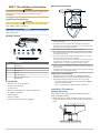
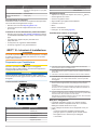
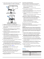
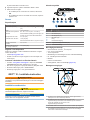
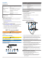
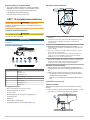
Package Contents
Item Description
À
GRF™ 10
Á
M4 screw (×5)
Â
M6 locknut (×2)
Ã
M6 nut (×2)
Ä
Washer
Å
Tiller arm mount
Æ
Ball joint assembly (×2)
Ç
Threaded rod
Tools Needed
• Drill and
1
/
8
in. (3.2 mm) drill bit
• 8 and 10 mm wrenches
• 10 mm socket
• Metal saw appropriate for cutting a threaded rod
• #2 Phillips screwdriver
• Tape measure
• Pencil or marker
• Extension cables, if necessary (page 2)
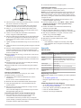
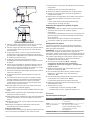
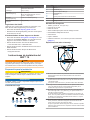
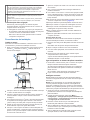
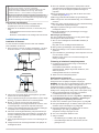
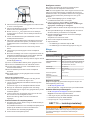
Mounting Considerations
À
The sensor must be installed parallel to the tiller arm while the
rudder is amidships.
Á
The distance from the rotation axis of the tiller to the ball-joint
assembly must be the same as the distance from the rotation axis
of the sensor to the ball joint assembly.
Â
The sensor and rudder rotation axes must be aligned.
Ã
The maximum range of travel from stop to stop is 140° (70º from
the center position to each stop). Exceeding this range may result
in damage to the sensor.
Ä
The rod that connects the sensor to the tiller arm is 11.8 in. (300
mm) long, and can be shortened if needed.
The rod should be level when connected to the sensor and rudder.
If a perfectly level installation is not possible, the rod must be
installed within +/- 5º off level in order to function correctly.
Å
The rod should be installed perpendicular to the tiller arm and
sensor, using the second hole from the tip of the sensor for the ball-
joint connector.
Although the second hole is preferred, the other holes may be used
if necessary for the installation location.
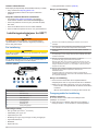
Connection Considerations
• This sensor can be connected to a compatible Garmin
®
autopilot system with a 12-pin rudder feedback connector.
• The cable connected to the sensor is 78 in. (2 m) long.
◦ If needed, extension cables for the sensor are available
from your Garmin dealer.
◦ Do not cut the sensor cable to extend or shorten it.
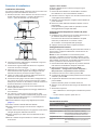
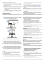
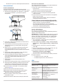
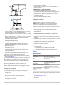
Installation Procedures
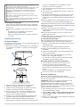
Installing the Sensor
For the best results, keep the rudder amidships during the
sensor-installation process.
1
Rotate the sensor counter-clockwise so the arrows on the
back
À
line up in the center
Á
before marking the mounting
holes.
2

2
Place the sensor in the chosen mounting location, and mark
the center of the three mounting holes.
3
Place the tiller-arm mount on the tiller arm in the chosen
location, and mark the center of the two mounting holes.
4
Using a
1
/
8
in. (3.2 mm) bit, drill three pilot holes on the
mounting surface for the sensor, and two pilot holes on the
tiller arm for the tiller-arm mount.
5
Fasten one of the ball-joint assemblies to the tiller-arm
mount, using the included M6 locknut.
6
Place the other ball-joint assembly into the appropriate hole
on the sensor (typically the second hole from the tip), and
fasten it with the included washer and locknut, using a 10
mm socket.
7
Tighten the ball-joint assemblies using a 8 mm wrench at the
base.
8
Fasten the sensor to the mounting surface using the included
screws.
9
With the rudder amidships and the sensor at center position,
measure the distance from the ball-joint assembly on the
sensor to the location where you plan to attach the tiller-arm
mount to the tiller arm.
10
If the threaded rod is too long, you must cut it to the correct
length (page 3).
11
Thread both of the standard M6 nuts onto the threaded rod.
12
Thread the rod into the ball-joint assembly connected to the
sensor.
13
Thread the other end of the rod into the ball-joint assembly
connected to the tiller-arm mount.
14
Fasten the tiller-arm mount to the tiller using the included
screws.
15
Tighten the M6 nuts on the threaded rod against both of the
ball-joint assemblies.
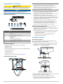
Cutting the Threaded Rod
If the included threaded rod is too long for your chosen
installation location, you must cut it.
1
Thread one of the included standard M6 nuts onto the
threaded rod.
Do not use one of the included M6 locknuts.
2
Measure and mark the threaded rod with electrical tape.
3
Using the appropriate saw, cut the threaded rod at the
marked location.
4
Remove the nut from the threaded rod, turning it counter-
clockwise over the cut area.
The nut should straighten any threads that may have been
damaged while cutting the rod.
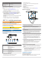
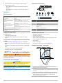
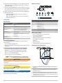
Connecting the Device to the Autopilot System
1
Route the cable from the sensor to the orange 12-pin
connector on the ECU of the autopilot system.
The installation instructions provided with your autopilot
system will help you identify where this connector is located.
If needed, extension cables are available.
2
Connect the sensor to the autopilot system.
Configuring the Sensor
When connected to a Garmin autopilot system, the sensor is
configured using the autopilot helm control.
NOTE: If an error appears during these steps, the sensor may
have reached the limit of its movement range. Make sure the
sensor was installed correctly. If the problem persists, bypass
this error by moving the rudder to the farthest position that does
not report an error.
1
Enter Dealer Mode by following the procedures in your
autopilot installation instructions.
2
From the Heading screen, select Menu > Setup > Dealer
Autopilot Configuration > Steering System Setup >
Rudder Sensor Setup.
3
Position the rudder so that the boat would steer fully
starboard, and select OK.
4
After the starboard calibration is complete, position the
rudder so that the boat would steer fully port, and select OK.
5
After the port calibration is complete, center the rudder
position, let go, and select Begin.
The autopilot takes control of the rudder.
6
Wait while the autopilot calibrates the rudder.
7
Select an option:
• If the calibration completes successfully, select OK.
• If the calibration did not complete successfully, repeat
steps 2–6.
Appendix
Specifications
Specification Measurement
Dimensions (H×W×D) 2
15
/
64
× 2¾ × 7
17
/
32
in. (60.8 × 70 × 191.4
mm)
Weight 5.54 oz. (157 g)
Temperature range From 5°F to 158°F (from -15°C to 70°C)
Material Polyoxymethylene (POM), waterproof to IEC
60529 IPX7 standards
Cable length 6½ ft. (2 m)
Max cable extension 49 ft. (15 m)
Up to three 16 ft. 4 in. (5 m) extensions
Nominal input voltage 4.5–5.5 Vdc
Compass-safe
distance
3.2 ft. (1 m)
Registering Your Device
Help us better support you by completing our online registration
today.
• Go to http://my.garmin.com.
• Keep the original sales receipt, or a photocopy, in a safe
place.
Contacting Garmin Product Support
• Go to www.garmin.com/support and click Contact Support
for in-country support information.
• In the USA, call (913) 397.8200 or (800) 800.1020.
• In the UK, call 0808 2380000.
• In Europe, call +44 (0) 870.8501241.
3
Page is loading ...
Page is loading ...
Page is loading ...
Page is loading ...
Page is loading ...
Page is loading ...
Page is loading ...
Page is loading ...
Page is loading ...
Page is loading ...
Page is loading ...
Page is loading ...
Page is loading ...
Page is loading ...
Page is loading ...
Page is loading ...
Page is loading ...
Page is loading ...
Page is loading ...
Page is loading ...
Page is loading ...
Page is loading ...

© 2012 Garmin Ltd. or its subsidiaries www.garmin.com/support
-
 1
1
-
 2
2
-
 3
3
-
 4
4
-
 5
5
-
 6
6
-
 7
7
-
 8
8
-
 9
9
-
 10
10
-
 11
11
-
 12
12
-
 13
13
-
 14
14
-
 15
15
-
 16
16
-
 17
17
-
 18
18
-
 19
19
-
 20
20
-
 21
21
-
 22
22
-
 23
23
-
 24
24
-
 25
25
-
 26
26


Garmin GRF 10 Rorfeedback-sensor Installation guide
- Type
- Installation guide
Ask a question and I''ll find the answer in the document
Finding information in a document is now easier with AI
in other languages
- italiano: Garmin GRF 10 Rorfeedback-sensor Guida d'installazione
- français: Garmin GRF 10 Rorfeedback-sensor Guide d'installation
- español: Garmin GRF 10 Rorfeedback-sensor Guía de instalación
- Deutsch: Garmin GRF 10 Rorfeedback-sensor Installationsanleitung
- Nederlands: Garmin GRF 10 Rorfeedback-sensor Installatie gids
- português: Garmin GRF 10 Rorfeedback-sensor Guia de instalação
- dansk: Garmin GRF 10 Rorfeedback-sensor Installationsvejledning
- polski: Garmin GRF 10 Rorfeedback-sensor Instrukcja instalacji
- svenska: Garmin GRF 10 Rorfeedback-sensor Installationsguide
- suomi: Garmin GRF 10 Rorfeedback-sensor Asennusohje
Related papers
-
Garmin GHP 12 autopilotsystem Installation guide
-
-
Garmin Reactor 40 autopilot til pahngsmotorer Installation guide
-
Garmin Reactor 40 Kicker Autopilot Installation guide
-
Garmin Nexus Owner's manual
-
Garmin Kabelgebundenes GHS11-VHF-Handgerat Owner's manual
-
Garmin GPSMAP® 942 User guide
-
-
-
Garmin GPSMAP 722xs og GMR 18 HD+-pakke User guide
Other documents
-
Lucent Technologies GRF 400 Getting Started
-
 Telldus 15261 Door/Window Sensor Bluetooth User manual
-
 Elkron SP900/10 Installation guide
-
 STREX SP181 User manual
-
 Neomounts ds15-625wh1 User manual
-
 Hangar 9 HAN5280 Owner's manual
-
 Hangar 9 HAN2390CDLE60T Owner's manual
-
Medtronic BIS Sensor User manual
-
-
Horizon Hobby Hangar 9 Ki-43 Oscar 60cc Owner's manual


