Page is loading ...

XTrac Installation manual
SECTIONAL
AND TIP-UP
GARAGE DOOR
OPENER

Company ProfileCompany Profile
CENTURION SYSTEMS (Pty) Ltd reserves the right to make changes to the products described in this manual without notice
and without obligation of CENTURION SYSTEMS (Pty) Ltd to notify any persons of any such revisions or changes.
Additionally, CENTURION SYSTEMS (Pty) Ltd makes no representations or warranties with respect to this manual.
No part of this document may be copied, stored in a retrieval system or transmitted in any form or by any means electronic,
mechanical, optical or photographic, without the express prior written consent of CENTURION SYSTEMS (Pty) Ltd.
Sales and support throughout
Southern Africa and over
50 countries worldwide
100%
testing of
products
In-house
R & D
development
team
Manufacture to
international
quality standard
ISO 9001:2008
1986 1990 1995 1999
Competent
after-sales
technical support
Centurion Systems
Today

Contents
IMPORTANT SAFETY INSTRUCTIONS 1
1 Product warranty and exclusions 5
2 Assembly instructions 6
2.1 Identify Garage Door type 6
2.2 Identify installation method 6
2.3 Assembly 7
3 Installation instructions 10
3.1 Header bracket mounting 10
3.2 Towing bracket mounting 11
3.3 Attaching Drive Rail to header bracket 11
3.4 Mounting Drive Rail Assembly to ceiling 11
3.5 Attaching Bent Towing Arm 13
3.6 Connecting to Power Supply 13
3.7 Engaging / Disengaging 13
4 Settings and adjustments 15
4.1 Door travel adjustment 15
4.2 Safety obstruction force adjustment 16
4.2.1 Adaptive Mode 16
4.2.2 Manual Mode 18
5 Options and Features 20
5.1 Accessory Connections 20
5.2 Autoclose 20
5.3 Back Jump 21
5.4 Dual Power 21
5.5 Control Box 22
5.6 Courtesy Lamp 24
5.7 Dipswitches 24
5.8 Door Service Monitor 25
5.9 Remote controls 25
5.10 Wireless wall switch 26
5.11 Learn Button 26
5.12 LED Indicator 26
5.13 Run button 27
5.14 Safety beams 27
5.15 Safety reverse 28
5.16 Soft start 28

5.17 Soft stop 28
5.18 Speed control 28
5.19 Maintenance 29
6 Technical specifications 30
7 Troubleshooting guide 31

IMPORTANT
Safety Instructions
ATTENTION
To ensure the safety of people, it is important that you read
all the following instructions. Incorrect installation or
incorrect use of the product could cause serious harm to
people.
The installer, being either professional or DIY, is the last
person on the site who can ensure that the operator is safely
installed, and that the whole system can be operated safely.
PLEASE READ CAREFULLY AND ADHERE TO ALL
SAFETY AND INSTALLATION RECOMMENDATIONS
The installation of your new Automatic Garage Door
Opener (herein after referred to as “XTrac”) must be
carried out by a technically qualified or licensed person.
Attempting to install or repair the XTrac without suitable
technical qualification may result in severe personal
injury, death and / or property damage
The XTrac must only be installed on a properly balanced
well functioning garage door. An improperly balanced or
malfunctioning garage door could cause serious personal
injury, death and / or property damage. Have a
qualified person check and if required, make repairs to
your garage door before installing the XTrac. The garage
door is deemed to be well balanced and aligned if it;
Requires an equivalent amount of applied force to
either manually open or no more than 150N (15kg) of
applied force to either manually open or close, and
Does not rise or fall more than 100mm when released
at any point between fully open or fully closed
positions
Does not rub on or incorrectly make contact with any
supporting or surrounding structures, and
The horizontal tracks have been installed level, and
The door panels have been installed level, and
The vertical tracks have been installed plumb, and
The junction between the curved horizontal track and
the vertical track does not cause the door to “jump”
The counterbalance springs on sectional type garage
doors must be properly lubricated between all of the coils
with heavy automotive bearing grease.
Page 1

Page 2
Failure to adequately lubricate the springs may result
in one or more of the following symptoms:
Counterbalance springs may become rusty over time
resulting in additional operating friction between the
coils which may cause the XTrac to malfunction
Seasonal temperature changes may cause the garage
door springs to expand and / or contract. The
resultant increase and / or decrease in operating
friction may cause the XTrac to malfunction. Properly
lubricating the springs will help to minimize changes
in operating friction due to the effects of seasonal
temperature change
Remove or render inoperative all existing locks and
ropes prior to installation of the XTrac
Repairs to the garage door must be carried out by
technically qualified persons. Attempting to repair the
garage door without suitable technical qualification may
result in severe personal injury, death and / or property
damage
Where possible, install the XTrac at least two meters or
more above the ground. Adjust the Engage / Disengage
Cord so that it hangs approximately 1.8 meters from the
ground
The Header Bracket carries ALL of the opening and
closing thrust of the XTrac and as such must be securely
fastened to a rigid, structural member of the garage wall
or ceiling. It is entirely up to the installer to determine
the fixing method and the structural suitability of the
fixing points
The ceiling structure must be adequate to support the
weight of the XTrac. It is entirely up to the installer to
determine the structural suitability of the fixing points
The Engage / Disengage Instruction Tag must remain
attached to the Engage / Disengage Cord.
Locate the Wall Switch;
within site of the garage door, and
at a minimum height of 1.5 meters above the ground
so that it remains out of the reach of small children,
and
away from all moving parts of the garage door
The Entrapment Warning Label must be secured in a
prominent position adjacent to the wall switch
The XTrac must be connected to a properly earthed
general purpose 220-240V AC power outlet which has
been installed by a qualified electrical contractor.
Do not connect the XTrac to the power outlet until this
manual instructs you to do so

Subsequent to installation and adjustment, the XTrac
must stop and reverse direction when it comes into
contact with a 35mm high solid object placed on the floor
under the garage door
The correct function of the Safety Obstruction Force
System should be checked on a monthly basis
Never use the XTrac unless the garage door is in full
view and free from any object which may impede the
movement of the garage door such as cars, children
and or adults
Never allow children to operate the XTrac
Never operate the XTrac when any persons are under or
near the path of the garage door. Children must be
supervised at all times when near the garage door and
when the XTrac is in use
Never attempt to disengage the XTrac to manual
operation when there are children / persons and or
solid objects including motor vehicles under or near the
path of the garage door as the garage door may fall
sharply upon Manual Release from the XTrac
Never attempt to open or close the garage door by
pulling on the Engage / Disengage Cord
Never attempt to make any repairs or remove covers
from the XTrac without first disconnecting the power
supply cord from the main power supply
Removal of the XTrac's protective covers must only be
performed by a technically qualified person. Attempting
to remove the protective covers or repair the XTrac
without suitable technical qualification may result in
severe personal injury, death and/or property damage
For additional safety we strongly recommend the
inclusion of Safety Beams. Although the XTrac
incorporates a pressure sensitive Safety Obstruction
Force system the addition of Safety Beams will greatly
enhance the operating safety of an automatic garage
door and provide additional peace of mind. In some
countries it is a mandate of law to fit Safety Beams. It is
the sole responsibility of the owner / installer to fit Safety
Beams in those countries that so require
Always ensure that the garage door is fully open &
stationary before driving in or out of the garage
Always ensure the garage door is fully closed and
stationary before moving out of its view
Adjustments to the Safety Stop / Reverse Force settings
must only be carried out by a technically qualified
person. Attempting to adjust the settings without
uitable technical qualification may result in severe
personal injury, death and / or property damage
Keep hands and loose clothing clear of the XTrac and
garage door at all times
Page 3

In order for the Safety Obstruction Force system to
function it must first encounter an obstruction in the
form of an object / person on to which some force MUST
be exerted. As a result the object / person / garage door
may suffer DAMAGE AND OR INJURY
The Safety Obstruction System is designed to work on
STATIONARY objects only. Serious personal injury, death
and or property damage may occur if the garage door
comes into contact with a moving object during an open
or close cycle
Page4
MOVING GARAGE DOOR CAN CAUSE SERIOUS INJURY OR DEATH!
KEEP CLEAR! DOOR MAY MOVE AT ANY TIME!
DO NOT ALLOW CHILDREN TO PLAY IN AREA
OR OPERATE DOOR.

All CENTURION products are manufactured with extreme care, thoroughly inspected and
tested. All CENTURION products are warranted against faulty materials and workmanship
for a period of 24 months from the date of invoice. However, it is expressly noted that
batteries carry a six month warranty due to the nature of these products being such that
they are subject to possible misuse which is beyond the control of Centurion Systems.
The warranty will cover the repair or replacement, at the discretion of Centurion Systems,
of such faulty materials or parts free of charge provided that the equipment is returned to
our workshop. The workmanship of the installation of the products carried out by any third
party is specifically not covered under this warranty (please consult with your installer
about their workmanship warranty terms and conditions). For equipment not of
CENTURION's manufacture the warranty as supplied by the original manufacturer will
apply.
No claims whatsoever will be recognised under the terms of this warranty which
pertain to damage, injury, cost or expense, suffered by persons and or to
property, which either directly or indirectly arise out of any one of the following
occurrences:
a. Failure to install the product in accordance with the installation instructions
provided by Centurion Systems.
b. Failure to abide by the safety instructions provided by Centurion Systems.
This warranty will not apply to any equipment which:
a. Has not been installed in accordance with the installation instructions
provided.
b. Has been subject to misuse or which has been used for any purpose other
than that designed for by the manufacturers.
c. Has damage caused as a result of handling during transit, atmospheric
conditions (including lightning), corrosion of metal parts, insect infestation,
power surges or other forces outside of the control of Centurion Systems.
d. Has been repaired by any workshop and or person NOT previously
authorised by Centurion Systems.
e. Has been repaired with components not previously tested, passed or
authorised by Centurion Systems.
1. Product warranty and exclusions
Page 5

2.1 Identify Garage Door type
Identify the garage door type and then select the preferred installation method
(Section.2.2) and assembly type (Section.2.3) that is best suited to the application.
2.2 Identify installation method
Method A -(Sectional door )
Use 3000mm long one piece or 3000mm three piece Drive Rail
The standard 3000mm Drive Rail will lift a door up to 2440mm high. (optional
Drive Rail extension kit is available for doors over 2440mm high)
XTrac is supported by the Drive Rail Hanger which is hung from the ceiling by
appropriate hanging material
Header Bracket may be mounted on front wall of garage or on ceiling adjacent to
the front wall
Method B -(Jamb type Tip-Up door )
Use 2000mm single piece rail or make up using two rail sections from the three
piece rail kit
XTrac is supported by the Drive Rail Hanger which is hung from the ceiling by
appropriate hanging material
Drive Rail must be angled as shown depicted in “Method B” so that the underside
of the Drive Unit is in line with underside of the garage door when the garage
doors are in the fully open (horizontal) position
Header Bracket may be mounted on front wall of garage or on the ceiling adjacent
to the front wall
Page 6
2. Assembly instructions
Method A
Installation to sectional door Installation to jamb-type tip up door
Towing bracket approx 1/3
of the way down from the
top panel. Bent towing arm
must be used and connected
to door with straight towing
arm connected to drive unit
Towing arm to top edge of
door. Bent towing arm must
be used and connected to
door with straight towing
arm connected to drive unit
Method B
FIGURE 1.

2.3 Assembly
2.3.1 General assembly
Open the packing carton and expose the XTrac components as depicted in
Figure.2
Orientate the Drive Rail (Figure.2-A) so that the Terminal Bracket (Figure.3-G)
faces towards the garage door
Locate the Drive Unit (Figure.2-C) and slide it into the Drive Rail and at the
same time insert the Drive Chain (Figure.1-B) into the Drive Unit. Slide the
Drive Unit at least 500mm in from the end of the Drive Rail
Note: Before attempting to insert the Drive Chain into the Drive Unit ensure
that the Drive Unit is disengaged (Refer Section.10)
Locate the Close Limit Prong (Figure.2-D) and slide it into the Drive Rail
Locate the Drive Rail Hanger (Figure.2-E) and slide it around the outside of the
Drive Rail. Make sure that the M8 dome head mounting bolts have been fitted
to the Drive Rail Hanger
Insert the Control Box (Figure.3-F) into the Drive Rail
Insert the Drive Chain into the Tensioning Block (Figure.2A-F1) and then “Twist
and Lock” the Drive Chain into place (Figure.1A-F2)
Use a 12 mm socket wrench to tighten the Drive Chain Tensioner Bolt to the
point where the underside of the Bolt Head aligns with the Indicator Arrow on
the Terminal Bracket.(Figure.2B-G1)
Independent mounting of Control Box
With either of the methods A or B the Control Box may be mounted independently of
the Drive Rail.
An optional instruction sheet and fitting kit;
I. “FKA” is available for mounting the Control Box on the ceiling adjacent to the
Drive Rail.
II. “FKB” is available for mounting the Control Box on a side wall of the garage.
Page 7

G
A
B
C
D
E
F
G
G1
Figure 3b
F
F1
F2
Figure 3a
Page 8
Towards Garage Door
FIGURE 2. SECTIONAL UNIT ASSEMBLY DEPICTED
FIGURE 3. Tensioning of the chain

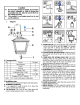
2.3.2 Attaching Straight Towing Arm
Remove the Drive Unit cover (Figure.4A) by pulling outwards and upwards, on
both sides, at the location marked by the arrow.
Insert the Straight Towing Arm through the slot in the cover (Figure.4B)
Note: use the end of the arm which has only one single hole.
Attach the arm to the Drive Unit using the short clevis pin and spring clip
provided (Figure.4B) and then replace the cover.
2.3.3 Options selection
Refer to Section.5.7 – Dipswitches and the sub section “functionality” and
select the required dipswitch functionality as required. Detailed explanation of
the different functions is provided under “Options and Features”
Section 5.1 – 5.19.
Refer to Section.5.1 – Accessory Connections to determine the external
accessory wiring that is required
To access the Dipswitches and Accessory Connectors remove the Control Box
cover (Figure.5) by first removing the fixing screw, located under the light
cover and then pulling outwards and upwards, on both sides of the cover, at
the location marked by the arrow
Once functionality selection and wire connection has been completed replace
the cover
The XTrac is now fully assembled and ready for installation
Figure 4A
Page 9
Remove cover
fixing screw
under light
cover
Figure 4B
FIGURE 4. ATTACHING STRAIGHT TOWING ARM
FIGURE 5. ATTACHING STRAIGHT TOWING ARM

3. Installation instructions
3.1 Header bracket mounting
Important Note: Before commencing the installation ensure that you have
carefully read and understood the Safety Recommendations outlined in
pages 1 to 4 of this manual. In particular, ensure that the installation of
the garage door complies with the requirements specified in points 3, 4 and
5. Make any necessary adjustments to the garage door BEFORE commencing
the installation!
Determine the highest arcing point of the garage door and mark this as a
horizontal line on the header above the top edge of the garage door.
(Figures.6 and 7)
Determine the Garage Door Centre Line and mark a vertical line on the header
above the door. (Figure.7)
Place the Header Bracket on the wall as depicted in Figure.7 and ensure that the
bottom edge of the bracket is no more than 50mm above the Highest Arcing
Point. Mark the location of the two outer most screw holes
Drill two screw holes and use screws of at least 8mm diameter. x 50mm long to
secure Header Bracket to Header
Important notes:
a. The Header Bracket carries ALL of the opening and closing thrust of the
XTrac and as such must be securely fastened to a rigid, structural
member of the garage. It is entirely up to the installer to determine the
fixing method and the structural suitability of the fixing points.
b. Mounting the Drive Rail more than 50mm above the Highest Arcing
Point of the garage door may cause the Drive Rail to flex excessively.
Always ensure that the bottom edge of the Drive Rail is located within
50mm of the top edge of the top panel of the garage door. (Figure.8)
Figure 7Figure 6
Page 10
50mm or less
Highest arcing point
Spring clip
Clevis pin
Top of garage
Header bracket
Towing bracket
Highest arcing point
FIGURE 6 AND 7. HEADER BRACKET MOUNTING
50mm
Garage Door center line

3.2 Towing bracket mounting
Determine the Garage Door Centreline (Figure.6) and affix the Towing Bracket to
a structural member of the garage door. The Towing Bracket should be mounted
with reference to the top edge of the garage door in accordance with the
appropriate diagram as depicted in Section.2.1 Method A or B
Mark the location of the holes. (four holes if using self drilling screws – two holes
if using screws with nuts)
Drill the screw holes with an appropriate drill and securely mount the Towing
Bracket to the garage door using screws of at least 6mm diameter
Important notes:
a. It is recommended to use fixing screws and nuts rather than self drilling
screws.
b. For a sectional type garage door the pivot point of the Towing Bracket
should be located approx one third of the way down from the top edge
of the top panel. For a tip-up type garage door the pivot point should be
as close to the top edge of the garage door as possible.
3.3 Attaching Drive Rail to Header bracket
With the garage door in the fully closed position - lay the assembled XTrac on the
garage floor in line with the Centreline of the garage door so that the Control Box
is furthest from the garage door
Important Note: avoid scratches and potential damage to the XTrac plastic covers
by placing the Control Box and Drive Unit on cardboard or foam
Raise the Drive Rail up to the Header Bracket so that the Drive Rail sits in
between the ears of the Header Bracket. (Figure.8)
Align the mounting holes of the Header Bracket and Terminal Bracket and fully
insert the long clevis pin and secure it with the spring clip
3.4 Mounting Drive Rail assembly to ceiling
Raise the Drive Rail assembly off the floor and rest it on a support high enough
that the Drive Rail runs parallel to the ground. (Figure.8) depicts typical sectional
type garage door installation)
Important Note: Do not lift the XTrac by the Control Box or damage may occur.
Always lift the XTrac via the Drive Rail
Carefully open the garage door and ensure that no part of it comes into contact
with the Drive Rail or the Control Box during its entire movement
Align the Drive Rail with the centreline of the garage door.
Slide the Drive Rail Hanger along the drive rail (up to max 600mm from the
Control Box) in order to align it with a structural member of the garage. Securely
fasten the Drive Rail Hanger to the structural member of the garage using two
lengths of appropriate hanging material. (Figure.9)
Once the Drive Rail is hung it should sit parallel to the floor along both planes.
(For sectional doors only. For jamb-type tilt door refer page 7 Method B)
Page 11

Important notes:
a. With the garage door in the fully open position the underside of the Drive
Rail should be no more than 50mm above the highest arcing point for its
entire length. Mounting the Drive Rail more than 50mm above the Highest
Arcing Point of the garage door may cause the Drive Rail to flex
excessively. (Figure. 9)
b. The ceiling structure must be adequate to support the weight of the
XTrac. It is entirely up to the installer to determine the structural
suitability of the fixing points.
Page 12
Figure 8
Figure 9
50mm or Less
A mode: any dimension
M mode: 225mm
Drive unit
Rail
Straight towing arm
Bent towing arm
Towing bracket
Door
Header
bracket
Figure 10
Figure 11
FIGURE 8 AND 9. MOUNTING DRIVE RAIL ASSEMBLY TO CEILING
FIGURE 10 AND 11. MOUNTING DRIVE RAIL ASSEMBLY TO CEILING
50mm or Less

3.5 Attaching Bent Towing Arm
Close the garage door.
Attach the Bent Towing Arm to the Towing Bracket (use the end of the arm which
has only one hole)
With the Drive Unit disengaged (Figure.12) position the Drive Unit in either one of
the following ways;
I. Adaptive Mode ~ any distance from the end of the Drive Rail.(Figure.11)
II. Manual Mode - 225mm from the end of the rail to the front of
the Drive Unit. (Figure.11)
Note: For an explanation of Adaptive and Manual Modes refer to section on
Obstruction Force on page 16.
Bring the Straight and Bent Towing Arms together and align the two furthest apart
sets of holes
Important Note: The two arms should be connected in a way that makes
them as long as possible.
Securely fix the arms together using two 8mm screws and nuts
3.6 Connecting to power supply
Plug the XTrac into a properly earthed 220 to 240V AC power outlet
Ensure that no excess power cord hangs below the Control Box
3.7 Engaging / Disengaging
The unique engage / disengage mechanism provides the following features:
a. Positive garage door locking even during power outages.
b. Re-engagement in any position without the need to line up chain and carriage
components.
Functionality
TO DISENGAGE - pull down on the release handle (Figure.12) until a click is “felt”
and then release the handle
TO ENGAGE - pull down on the release handle once again until a click is “felt” and
then release the handle
Page 13

Important notes:
a. Never attempt to open or close the garage door by pulling on the release
handle. Doing so may result in SERIOUS PERSONAL INJURY and or
PROPERTY DAMAGE.
b. Always disengage the XTrac with the garage door in the fully closed
position.
c. If attempting to disengage the XTrac from any position other than with
the garage door fully closed ensure that there are no persons and
or property near or directly under the path of the door.
Page 14
Engage
Release handle
Disengage
FIGURE 12. ENGAGING / DISENGAGING

4. Settings and adjustments
4.1 Door travel adjustment
The Drive Rail mounted Limit Prongs provide a one to one ratio between Limit
Prong movement and garage door movement thereby ensuring 100% accuracy
and ease of adjustment. Garage door fully open and fully closed positions can be
easily adjusted by moving the Limit Prong to the desired location in order to
increase or decrease garage door travel
Door travel adjustment – Close direction
Locate the Close Direction Limit Prong within the Drive Rail - nearest to front wall
of garage (Figure.13)
Loosen the Limit Prong Lock Screw by half a turn and slide the Limit Prong
towards the front wall of the garage to increase garage door travel and away from
the front wall to decrease garage door travel
Re-tighten the Limit Prong Lock Screw once correct adjustment has been attained
Note: The Limit Prongs work on a one to one ratio with the garage door, meaning
that if the Limit Prong is moved by 10 mm then the garage door will also move
by 10 mm
Door travel adjustment – Open direction
Locate the Open Direction Limit Prong within the Drive Rail – nearest to Control
Box. (Figure.13)
Loosen the Limit Prong Lock Screw by half a turn and slide the Prong towards the
Control Box to increase garage door travel and away from the Control Box to
decrease travel
Re-tighten the Limit Prong Lock Screw once correct adjustment has been attained
Note: The Limit Prongs work on a one to one ratio with the garage door -
meaning that if the Limit Prong is moved by 10 mm then the garage door
will also move by 10 mm.
Lock screw
Open limit prong
Close limit prong
Page 15
Figure 13. Engaging / Disengaging

4.2. Safety Obstruction Force Adjustment
Dual Safety Obstruction Force Adjustment modes ensure that the XTrac can be
optimized to suit virtually any sectional or tip-up type garage door
Adaptive Mode – constantly monitors incremental drive force value changes that
occur due to seasonal conditions and / or garage door aging. Adaptive Mode
compensates for these variables by automatically adjusting Safety Obstruction
Force values during every complete cycle, resulting in enhanced safety and
minimized chances of garage door ghosting*.(Refer Section.4.2.1 for set-up
details)
Ghosting is defined as a Safety Stop or Safety Reverse without the garage door actually encountering an
obstruction
Manual Mode – features conventional one time Safety Obstruction Force value
adjustment and is more suited for use on badly worn or improperly balanced
garage doors. (Refer Section.4.2.2 for set-up details)
4.2.1 Adaptive (A) Mode
Enabling
If Manual Mode is your desired selection then skip to Section.4.2.2
If Adaptive Mode is already enabled then skip to the next section titled
“Functionality”
To enable Adaptive Mode carry out the following procedure;
I. switch off power at power supply.
II. remove the Courtesy Lamp and Control Box Covers to expose the
Control Board (Refer Section.5.6 for removal and replacement details).
III. select Dipswitch No.1 to the “ON” position (Figure.16).
IV. replace the Control Box and Lamp Covers.
V. switch power on at power supply.
Functionality
In order to learn the required run time and drive force values the XTrac
will be required to complete five (manually activated) uninterrupted open
and close cycles.(commencing from the Close Limit Point)
During the course of the cycles the LED Indicator will quick flash and the
operating parameters will be learned in the following order;
I. Open Stroke 1 – Alignment stroke.
II. Close Stroke 1 – Learn run time between Open Limit
Point and Close Limit Point (during Close Cycle 1 the XTrac will not
Slow Stop).
III.Open Stroke 2 – Learn run time between Close Limit Point and Open
Limit Point (during Open Cycle 1 the XTrac will not Slow Stop)
IV. Close Stroke 2 – Learn Drive Force Values between Open Limit Point
and Close Limit Point.
V. Open Stroke 3 – Learn Drive Force Values between Close Limit Point
and Open Limit Point.
Once Learning has been successfully completed, the LED Indicator will
commence to slow flash
Page 16
*
/