Page is loading ...

NMEA 2000® TANK SENDER ADAPTOR
Part Number: 3125
INSTALLATION AND OPERATING INSTRUCTIONS
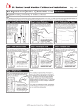
Sender Resistance
European 0-180
Tank Type
fuel
fresh water
waste water
live well
oil
black water
invalid
invalid
Switch Position
0
1
2
3
4
5
6
7
Applicable to REV E and above.
INTRODUCTION
The NMEA2000® Tank Sender Adaptor allows a standard resistive tank level sender to connect to the NMEA2000®
network.
It is configurable to either the European standard 0 - 180 (full) Ohm and the American standard 240 - 30 (full)
Ohm tank level senders.
It is also easily configured to indicate levels from Fuel, Fresh Water, Waste Water, Live Well, Oil and Black Water
(Sewage) tanks to the NMEA2000® network and configurable to identify up to 16 tanks of each type on a single
network.
The Tank Sender Adaptor is robustly constructed to the IEC60945 Maritime Navigational and Radiocommunications
Equipment Standard to ensure trouble free operation and high reliability. It is certified to the NMEA2000®
network standard version 2 and attaches to the network by a single Micro-C plug. It draws less than 50mA from
the network. No additional power cabling is required and the sender is simply connected to the T-adaptor.
SAFETY INSTRUCTIONS
This sender should only be installed by a person competent and experienced in working with electronic and
electrical systems on boats.
Before beginning work the battery should be disconnected to avoid the risk of a short circuit, a fire or an
explosion. Before drilling any holes to mount any unit or run any cabling always make sure it is safe to do so.
LOCATION AND INSTALLATION
The Tank Sender Adaptor is water resistant but NOT waterproof. It is designed to be located in a dry and
protected location in the cable run between the NMEA2000® network and the tank level sender. It does not need
to be attached to any surface but should be restrained from free movement by means of cable ties to the rest of
the cable run or similar.
WIRING
Connect the device, using the Micro Drop Trunk Cable provided, to an available T-connector on the backbone.
Ensure that both ends are mated securely and the retaining ring has been tightened correctly to ensure the
junction is waterproof. Note that this cable length may be extended to a maximum of 6 metres by using micro
drop cables.
The sender cable from the Tank Sender Adaptor (not supplied) should be connected to the two terminals on the
sender. The connection polarity of the sender wires is unimportant. Either way round will work correctly.
ENSURE THAT NO OTHER CABLES ARE CONNECTED TO THE TANK LEVEL SENDER.
SENDER RESISTANCE AND TANK CONTENTS
This adaptor is configured to either the European standard 0-180 or the American standard 240 - 30 Ohm tank
level senders and to the range of different tank contents by the sender type switch as per the following table.
0
F
E
D
C
B
A
9
8
7
6
5
4
3
2
1
0
F
E
D
C
B
A
9
8
7
6
5
4
3
2
1
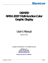
Micro Drop Trunk Cable
Sender Cable
(not supplied)
Resistive Tank Sender
(not supplied)
NMEA2000®
Tank Sender Adaptor
Part No. 3125
NMEA2000® Backbone and T-Adaptor
(not supplied)
Installation Diagram

American 240-30
fuel
fresh water
waste water
live well
oil
black water
invalid
invalid
8
9
A
B
C
D
E
F
0
F
E
D
C
B
A
9
8
7
6
5
4
3
2
1
0
F
E
D
C
B
A
9
8
7
6
5
4
3
2
1
TANK NUMBER
The NMEA2000® network protocol supports up to 16 tanks of each contents type. The adaptor is configured to
identify the tank number by means of the Tank Instance Switch as per the following table.
OPERATION
Once the adaptor has been installed there is no normal operator intervention required.
The unit has a blue LED which flashes every time the sender transmits a signal.
CALIBRATION
The adaptor is already calibrated and requires no further calibration.
OUTPUT MODE CONFIGURATION
The 3125 Tank Sender Adaptor has two output modes to choose from. PERCENTAGE LEVEL MODE is the default
setting and PERCENTAGE VOLUME MODE is the second option.
PERCENTAGE LEVEL MODE output from 0 – 100% indicates the percentage level of the fluid in the tank. When the
unit is in ‘Level Mode’ the blue LED flashes ONCE every 2.5 seconds, when a level message has been sent.
PERCENTAGE VOLUME MODE output from 0-100% indicates the actual fluid volume within the tank taking
allowance for the tanks internal shape. When the unit is in ‘Volume Mode’ the blue LED flashes TWICE rapidly
every 2.5 seconds when a volume message has been sent.
The Volume Mode PGN message is exactly the same as the Level Mode PGN message which means that the volume
can easily be shown on any NMEA2000 display that accepts Fluid Level PGNs from tank senders. The Volume Mode
tank data can be entered from any Oceanic Systems Display, that is equipped to set up this data. Please contact
us for more information on these displays. It can also be set up at manufacture, if the information is made
available at the time of ordering.
LEVEL MODE can be set with the Tank Instance Switch by setting the switch to ‘C’ and then placing a small magnet
on the ‘Magnet Calibration’ position for 5 seconds. The blue LED will light up for 2 seconds to indicate that the
unit registered the magnet. Then return the switch to it’s original position and the sender will transmit level
messages as indicated by the blue LED flashing ONCE briefly every 2.5 seconds.
VOLUME MODE can be set with the Tank Instance Switch by setting the switch to ‘D’, then placing the magnet on
the ‘Magnet Calibration’ position for 5 seconds. The blue LED will light up for 2 seconds to indicate that the unit
registered the magnet. When the switch is returned to it’s original positions the sender will transmit Volume
messages as indicated by the blue LED flashing rapidly TWICE every 2.5 seconds.
If the Volume Mode Tank Data has NOT been set up and the unit is accidently set to Volume Mode then the data
transmitted will actually be the Level Data so the unit remains fully functional.
1
2
3
4
5
6
7
8
9
10
11
12
13
14
15
16
Tank
Instance
0
1
2
3
4
5
6
7
8
9
A
B
C
D
E
F
Switch
Position
Tank Instance Switch
Sets Tank Number
Cable connectors to
Resistive Tank Sender
Sender Type Switch
Sets Sender type
Copyright © 2021 Oceanic Systems (UK) Ltd. All rights reserved. Our policy is one of continuous product improvement so product
specifications are subject to change without notice. Oceanic Systems products are designed to be accurate and reliable. However,
they should be used only as aids to vessel monitoring, and not as a replacement for traditional navigation and vessel monitoring
techniques. NMEA2000® is a registered trademark of the National Marine Electronics Association.
Oceanic Systems (UK) Ltd
Unit 10 -11 Milton Business Centre, Wick Drive,
New Milton, Hampshire, BH25 6RH, United Kingdom
Tel (UK): +44(0)1425 610022 Tel (USA): (844)898 6462
Fax: +44(0)1425 614794 Email: [email protected]
Web: www.osukl.com
LED
NMEA2000®
Network
Cable
Tank Instance set to ‘C’
0
F
E
D
C
B
A
9
8
7
6
5
4
3
2
1
0
F
E
D
C
B
A
9
8
7
6
5
4
3
2
1
0
F
E
D
C
B
A
9
8
7
6
5
4
3
2
1
Set Level Mode with a magnet
Blue LED lights
up for 2 seconds
0
F
E
D
C
B
A
9
8
7
6
5
4
3
2
1
0
F
E
D
C
B
A
9
8
7
6
5
4
3
2
1
Tank No. set to ‘D’
0
F
E
D
C
B
A
9
8
7
6
5
4
3
2
1
0
F
E
D
C
B
A
9
8
7
6
5
4
3
2
1
0
F
E
D
C
B
A
9
8
7
6
5
4
3
2
1
Set Volume Mode with a magnet
Blue LED lights
up for 2 seconds
0
F
E
D
C
B
A
9
8
7
6
5
4
3
2
1
0
F
E
D
C
B
A
9
8
7
6
5
4
3
2
1
3125 Diagram
/