Suzuki Jimny User manual

Category
Projection TVs
Type
User manual

This manual is also suitable for

IMPORTANT
WARNING/CAUTION/NOTE
Please read this manual and follow its instructions
carefully. To emphasize special information, the
words WARNING, CAUTION and NOTE have spe-
cial meanings. Pay special attention to the messages
highlighted by these signal words.
NOTE:
Indicates special information to make mainte-
nance easier or instructions clearer.
WARNING:
Indicates a potential hazard that could result
in death or injury.
CAUTION:
Indicates a potential hazard that could result
in vehicle damage.
WARNING:
This service manual is intended for authorized
SUZUKI dealers and qualified service me-
chanics only. Inexperienced mechanics or
mechanics without the proper tools and
equipment may not be able to properly per-
form the services described in this manual.
Improper repair may result in injury to the me-
chanic and may render the vehicle unsafe for
the driver and passengers.
()
x
()
x
()
x
()
x
()
x
()
x
()
x
()
x
()
x
()
x
()
x
()
x
()
x
()
x
()
x
()
x
()
x
()
x
FOREWORD
This SUPPLEMENTARY SERVICE MANUAL is a supplement to SF SERIES SERVICE MANU-
ALS mentioned in next page and has been prepared exclusively for the following applicable mod-
el.
Applicable model: SF310/SF413 of and after the vehicle identification numbers below.
Vehicle Identification Number (Vehicle Specification)
TSMMAA44S00600001 (SF310 3 door H/B 2WD)
TSMMAB44S00600001 (SF310 5 door H/B 2WD)
TSMMAA35S00600001 (SF413 3 door H/B 2WD)
TSMMAB35S00600001 (SF413 5 door H/B 2WD)
TSMMAB35S10600001 (SF413 5 door H/B 2WD)
TSMMSF35S00600001 (SF413 3 door H/B 4WD)
TSMMSG35S00600001 (SF413 5 door H/B 4WD)
TSMMAH35S00600001 (SF413 4 door N/B 2WD)
TSMMAH35S10600001 (SF413 4 door N/B 2WD)
When servicing the above applicable models, refer to this SUPPLEMENTARY SERVICE MANU-
AL first. If necessary information is not found in this SUPPLEMENTARY SERVICE MANUAL, re-
fer to RELATED MANUALS specified next page.
All information, illustrations and specifications contained in this literature are based on the latest
product information available at the time of publication approval. And used as the main subject
of description is the vehicle of standard specifications among others. Therefore, note that illustra-
tions may differ from the vehicle being actually serviced.
The right is reserved to make changes at any time without notice.
OVERSEAS SERVICE DEPARTMENT
COPYRIGHT SUZUKI MOTOR CORPORATION 2000
RELATED MANUALS
Related manuals listed below are in the chronological order with the latest one at the top. For the efficient use of
manuals, start with one at the top of the list (i.e., the latest one). If desired section, item or description is not found
in it, try next one in the list and do the same one by one till what is being searched is found.
MODEL
NO. RELATED SERVICE MANUAL APPLICABILITY
SF310/
SF413
1
SF310/SF413
WIRING DIAGRAM MANUAL
(99512-80E10-019)
This manual is prepared exclusively for the appli-
cable model mentioned in FOREWORD of this
supplementary service manual.
SF
SERIES
1
SF SERIES SUPPLEMENTARY
SERVICE MANUAL
(99501-80E00-xxx)
This manual describes the updated information
from the SF310 and SF413 Service Manuals
below.
SF310
(1 000 cc)
1
SF310 SUPPLEMENTARY
SERVICE MANUAL
(99501-60B00-xxx)
This manual describes the items that are updated
(modified and added) from the Service Manual
(99500-60B01).
(1
,
000
cc)
2
SF310 SERVICE MANUAL
(99500-60B01-xxx)
This manual is the base manual for the above
manual.
1
SF413 SUPPLEMENTARY
SERVICE MANUAL
(99501-63B30-xxx)
[Pub. No. G4203GE]
This manual describes the items that are updated
(modified and added) from the Service Manual
(99500-63B01).
SF413
(1,300 cc)
2
SF413 SUPPLEMENTARY
SERVICE MANUAL
(99501-63B20-xxx)
[Pub. No. G4202GE]
This manual describes the items for 4WD model
that are updated (modified and added) from the
Service Manual (99500-63B01).
(, )
2
SF413 SUPPLEMENTARY
SERVICE MANUAL
(99501-63B10-xxx)
This manual describes the items for SEDAN mod-
el that are updated (modified and added) from the
Service Manual (99500-63B01).
3
SF413 SERVICE MANUAL
(99500-63B01-xxx)
[Pub. No. G4200GE]
This manual is the base manual for the above
manuals.
SF
SERIES
(A/C)
1
AIR CONDITIONING BASIC
MANUAL (99520-02130-xxx)
This manual is the base manual of A/C system.
6
6
6-1
6A
6A1
6B
6C
6E1
6E1
6E2
6F
6F
6F1
6G
6H
6K
GENERAL INFORMATION
General Information
Maintenance and Lubrication
1A
1B
TABLE OF CONTENTS SECTION
0A
0B
7B
8
8A
8G
HEATING AND AIR CONDITIONING
Heater and Ventilation
Air Conditioning (Oprional)
ENGINE
General Information and Diagnosis
(TBI for G10)
General Information and Diagnosis
(TBI for G13)
General lnformation and Diagnosis
(SFI for G13)
Engine Mechanical (G10 Engine)
Engine Mechanical
(G13 1-cam 16-valves Engine)
Engine Cooling
Engine Fuel
Engine and Emission Control System
(TBI for G10)
Engine and Emission Control System
(TBI for G13)
Engine and Emission Control System
(SFI for G13)
Ignition System (TBI for G10)
Ignition System (TBI for G13)
Ignition System (SFI for G13)
Cranking System
Charging System
Exhaust System
TRANSMISSION, CLUTCH AND
DIFFERENTIAL
Automatic Transmission
BODY ELECTRICAL SYSTEM
Wiring Diagram
IMMOBILIZER CONTROL SYSTEM
1B
0B
0A
1A
6
6B
6C
6E1
6A1
6F
6G
6H
6K
7B
8
8A
8G
6-1
6A
6E2
6F1
6
6E1
6F
NOTE:
The screen toned Section 8A is contained in WIRING DIAGRAM MANUAL mentioned in
RELATED MANUALS.
GENERAL INFORMATION 0A-1
0A
SECTION 0A
GENERAL INFORMATION
CONTENTS
HOW TO USE THIS MANUAL 0A- 2. . . . . . . . . . . . . . . . . . . . . . . . . . . . . . . . . . . . . . . . . . . . . . . . . . . . . . . . . . . . . . .
PRECAUTIONS 0A- 3. . . . . . . . . . . . . . . . . . . . . . . . . . . . . . . . . . . . . . . . . . . . . . . . . . . . . . . . . . . . . . . . . . . . . . . . . . . .
Precaution for Vehicles Equipped with a Supplemental Restraint (Air Bag) System 0A- 3. . . . . . . . . . . . . . . .
General Precautions 0A- 6. . . . . . . . . . . . . . . . . . . . . . . . . . . . . . . . . . . . . . . . . . . . . . . . . . . . . . . . . . . . . . . . . . . . . .
Precautions for Catalytic Converter 0A- 9. . . . . . . . . . . . . . . . . . . . . . . . . . . . . . . . . . . . . . . . . . . . . . . . . . . . . . . . .
Precautions for Electrical Circuit Service 0A- 9. . . . . . . . . . . . . . . . . . . . . . . . . . . . . . . . . . . . . . . . . . . . . . . . . . . . .
Electrical Circuit Inspection Procedure 0A-12. . . . . . . . . . . . . . . . . . . . . . . . . . . . . . . . . . . . . . . . . . . . . . . . . . . . . .
Intermittent and Poor Connection 0A-15. . . . . . . . . . . . . . . . . . . . . . . . . . . . . . . . . . . . . . . . . . . . . . . . . . . . . . . . . . .
Precaution for Installing Mobile Communication Equipment 0A-16. . . . . . . . . . . . . . . . . . . . . . . . . . . . . . . . . . . .
Precaution in Servicing Full-Time 4WD Vehicle 0A-17. . . . . . . . . . . . . . . . . . . . . . . . . . . . . . . . . . . . . . . . . . . . . . .
IDENTIFICATION INFORMATION 0A-18. . . . . . . . . . . . . . . . . . . . . . . . . . . . . . . . . . . . . . . . . . . . . . . . . . . . . . . . . . . .
Vehicle Identification Number 0A-18. . . . . . . . . . . . . . . . . . . . . . . . . . . . . . . . . . . . . . . . . . . . . . . . . . . . . . . . . . . . . .
Identification Whether Vehicle Equipped with WU-TWC or Not 0A-18. . . . . . . . . . . . . . . . . . . . . . . . . . . . . . . . . .
Engine Identification Number 0A-18. . . . . . . . . . . . . . . . . . . . . . . . . . . . . . . . . . . . . . . . . . . . . . . . . . . . . . . . . . . . . . .
Transmission Identification Number 0A-18. . . . . . . . . . . . . . . . . . . . . . . . . . . . . . . . . . . . . . . . . . . . . . . . . . . . . . . . .
WARNING, CAUTION AND INFORMATION LABELS 0A-19. . . . . . . . . . . . . . . . . . . . . . . . . . . . . . . . . . . . . . . . . .
VEHICLE LIFTING POINTS 0A-20. . . . . . . . . . . . . . . . . . . . . . . . . . . . . . . . . . . . . . . . . . . . . . . . . . . . . . . . . . . . . . . . .
ABBREVIATIONS AND SYMBOLS MAY BE USED IN THIS MANUAL 0A-22. . . . . . . . . . . . . . . . . . . . . . . . . . .
FASTENER INFORMATION 0A-25. . . . . . . . . . . . . . . . . . . . . . . . . . . . . . . . . . . . . . . . . . . . . . . . . . . . . . . . . . . . . . . . .
Metric Fasteners 0A-25. . . . . . . . . . . . . . . . . . . . . . . . . . . . . . . . . . . . . . . . . . . . . . . . . . . . . . . . . . . . . . . . . . . . . . . . .
Fasteners Strength Identification 0A-25. . . . . . . . . . . . . . . . . . . . . . . . . . . . . . . . . . . . . . . . . . . . . . . . . . . . . . . . . . .
Standard Tightening Torque 0A-26. . . . . . . . . . . . . . . . . . . . . . . . . . . . . . . . . . . . . . . . . . . . . . . . . . . . . . . . . . . . . . . .
1. Flywheel bolts or drive plate bolts for A / T vehicle
6) Install oil pump. Refer to “Oil pump”.
7) Install flywheel (for M/ T vehicle) or drive plate
(for A/ T vehicle).
Using special tool, lock flywheel or drive plate, and
tighten flywheel or drive plate bolts to specified
torque.
Special Tool
(A): 09924-17810
Tightening Torque
(c): 78 N
.
m (7.8 kg-m, 56.0 lb-ft)
0A-2 GENERAL INFORMATION
HOW TO USE THIS MANUAL
1) There is a TABLE OF CONTENTS FOR THE WHOLE MANUAL
on the third page of this manual, whereby you can easily find the
section that offers the information you need. Also, there is a
CONTENTS on the first page of EACH SECTION, where the
main items in that section are listed.
2) Each section of this manual has its own pagination. It is indicated
at the top of each page along with the Section name.
3) The SPECIAL TOOL usage and TIGHTENING TORQUE
SPECIFICATION are given as shown in figure below.
4) A number of abbreviations are used in the text.
For their full explanations, refer to “ABBREVIATIONS AND
SYMBOLS MAY BE USED IN THIS MANUAL” of this section.
5) The SI, metric and foot-pound systems are used as units in this
manual.
6) DIAGNOSIS are included in each section as necessary.
7) At the end of each section, there are descriptions of SPECIAL
TOOLS, REQUIRED SERVICE MATERIALS and TIGHT-
ENING TORQUE SPECIFICATIONS that should be used for the
servicing work described in that section.
1. Air bag wire harness
2. Driver air bag (inflator) module
3. Passenger air bag (inflator) module
4. SDM
GENERAL INFORMATION 0A-3
PRECAUTIONS
PRECAUTION FOR VEHICLES EQUIPPED
WITH A SUPPLEMENTAL RESTRAINT (AIR
BAG) SYSTEM
WARNING:
D The configuration of air bag system parts are as shown in
the figure. When it is necessary to service (remove, rein-
stall and inspect) these parts, be sure to follow proce-
dures described in Section 9J. Failure to follow proper
procedures could result in possible air bag deployment,
personal injury, damage to parts or air bag being unable
to deploy when necessary.
D If the air bag system and another vehicle system both
need repair, Suzuki recommends that the air bag system
be repaired first, to help avoid unintended air bag deploy-
ment.
D Do not modify the steering wheel, dashboard, or any other
air bag system component. Modifications can adversely
affect air bag system performance and lead to injury.
D If the vehicle will be exposed to temperatures over 93_C,
200_F (for example, during a paint baking process), re-
move the air bag system components (air bag (inflator)
modules, sensing and diagnostic module) beforehand to
avoid component damage or unintended deployment.
DIAGNOSIS
D When troubleshooting air bag system, be sure to follow
DIAGNOSIS in Section 9J. Bypassing these procedures
may result in extended diagnostic time, incorrect diagnosis,
and incorrect parts replacement.
D Never use electrical test equipment other than that specified
in this manual.
WARNING:
Never attempt to measure the resistance of the air bag (in-
flator) modules (driver and passenger). It is very dangerous
as the electric current from the tester may deploy the air
bag.
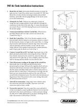
1. Slit on workbench
2. Workbench vise
3. Lower mounting bracket
ALWAYS CARRY AIR BAG (INFLATOR) MODULE
WITH TRIM COVER (AIR BAG OPENING) AWAY
FROM BODY.
ALWAYS PLACE AIR BAG (INFLATOR) MODULE
ON WORKBENCH WITH TRIM COVER (AIR BAG
OPENING) UP, AWAY FROM LOOSE OBJECTS.
0A-4 GENERAL INFORMATION
HANDLING AND SERVICING
WARNING:
D Many of service procedures require disconnection of
AIR BAG fuse and air bag (inflator) modules (driver and
passenger) from deployment loop to avoid an accidental
deployment.
Driver and Passenger Air Bag (Inflator) Modules
D For handling and storage of a live air bag (inflator) module,
select a place where the ambient temperature below 65_C
(150_F), without high humidity and away from electric
noise.
D When carrying a live air bag (inflator) module, make sure
the bag opening is pointed away from you. In case of an
accidental deployment, the bag will then deploy with mini-
mal chance of injury. Never carry the air bag (inflator)
module by the wires or connector on the underside of the
module. When placing a live air bag (inflator) module on
a bench or other surface, always face the bag up, away
from the surface. As the live passenger air bag (inflator)
module must be placed with its bag (trim cover) facing up,
place it on the workbench with a slit or use the workbench
vise to hold it securely at its lower mounting bracket. This
is necessary so that a free space is provided to allow the
air bag to expand in the unlikely event of accidental de-
ployment. Otherwise, personal injury may result.
D Never dispose of live (undeployed) air bag (inflator) mod-
ules (driver and passenger). If disposal is necessary, be
sure to deploy them according to deployment procedures
described in Section 9J before disposal.
D The air bag (inflator) module immediately after deploy-
ment is very hot. Wait for at least half an hour to cool it off
before proceeding the work.
D After an air bag (inflator) module has been deployed, the
surface of the air bag may contain a powdery residue.
This powder consists primarily of cornstarch (used to lu-
bricate the bag as it inflates) and by-products of the chem-
ical reaction. As with many service procedures, gloves
and safety glasses should be worn.
SDM
D During service procedures, be very careful when handling
a Sensing and Diagnostic Module (SDM). Never strike or
jar the SDM. Never power up the air bag system when the
SDM is not rigidly attached to the vehicle. All SDM and
mounting bracket fasteners must be carefully torqued
and the arrow must be pointing toward the front of the ve-
hicle to ensure proper operation of the air bag system. The
SDM could be activated when powered while not rigidly at-
tached to the vehicle which could cause deployment and
result in personal injury.
GENERAL INFORMATION 0A-5
CAUTION:
D Even when the accident was light enough not to cause air
bags to deploy, be sure to inspect system parts and other
related parts according to instructions under Repair and
Inspection Required after an Accident in Section 9J.
D When servicing parts other than air bag system, if shocks
may be applied to air bag system component parts, re-
move those parts beforehand.
D When handling the air bag (inflator) modules (driver and
passenger) or SDM, be careful not to drop it or apply an im-
pact to it. If an excessive impact was applied (e.g.,
dropped from a height of 91.4 cm (3 feet) or more), never
attempt disassembly or repair but replace it with a new
one.
D When grease, cleaning agent, oil, water, etc. has got onto
air bag (inflator) modules (driver and passenger), wipe off
immediately with a dry cloth.
D Air bag wire harness can be identified easily as it is cov-
ered with a yellow protection tube. Be very careful when
handling it.
D When an open in air bag wire harness, damaged wire har-
ness, connector or terminal is found, replace wire har-
ness, connectors and terminals as an assembly.
D Do not apply power to the air bag system unless all com-
ponents are connected or a diagnostic chart requests it,
as this will set a diagnostic trouble code.
D Never use air bag system component parts from another
vehicle.
D When using electric welding, be sure to temporarily dis-
able air bag system referring to Disabling Air Bag Sys-
tem under Service Precaution in Section 9J.
D Never expose air bag system component parts directly to
hot air (drying or baking the vehicle after painting) or
flames.
D WARNING/CAUTION labels are attached on each part of
air bag system components. Be sure to follow the instruc-
tions.
D After vehicle is completely repaired, perform Air Bag
Diagnostic System Check described in Diagnosis in
Section 9J.
0A-6 GENERAL INFORMATION
GENERAL PRECAUTIONS
The WARNING and CAUTION below describe some general precautions that you should observe when servicing
a vehicle. These general precautions apply to many of the service procedures described in this manual, and they
will not necessarily be repeated with each procedure to which they apply.
WARNING:
D Whenever raising a vehicle for service, be sure to follow the instructions under VEHICLE LIFTING
POINTS on SECTION 0A.
D When it is necessary to do service work with the engine running, make sure that the parking brake
is set fully and the transmission is in Neutral (for manual transmission vehicles) or Park (for automatic
transmission vehicles). Keep hands, hair, clothing, tools, etc. away from the fan and belts when the
engine is running.
D When it is necessary to run the engine indoors, make sure that the exhaust gas is forced outdoors.
D Do not perform service work in areas where combustible materials can come in contact with a hot
exhaust system. When working with toxic or flammable materials (such as gasoline and refrigerant),
make sure that the area you work in is well-ventilated.
D To avoid getting burned, keep away from hot metal parts such as the radiator, exhaust manifold, tail-
pipe, muffler, etc.
D New and used engine oil can be hazardous. Children and pets may be harmed by swallowing new or
used oil. Keep new and used oil and used engine oil filters away from children and pets.
Continuous contact with used engine oil has been found to cause [skin] cancer in laboratory animals.
Brief contact with used oil may irritate skin. To minimize your exposure to used engine oil, wear a
long-sleeve shirt and moisture-proof gloves (such as dish washing gloves) when changing engine
oil. If engine oil contacts your skin, wash thoroughly with soap and water. Launder any clothing or
rags if wet with oil, recycle or properly dispose of used oil and filters.
D Make sure the bonnet is fully closed and latched before driving. If it is not, it can fly up unexpectedly
during driving, obstructing your view and resulting in an accident.
CAUTION:
D Before staring any service work, cover fenders, seats and
any other parts that are likely to get scratched or stained dur-
ing servicing. Also, be aware that what you wear (e.g. but-
tons) may cause damage to the vehicles finish.
D When performing service to electrical parts that does not re-
quire use of battery power, disconnect the negative cable of
the battery.
GENERAL INFORMATION 0A-7
D When removing the battery, be sure to disconnect the nega-
tive cable first and then the positive cable. When reconnect-
ing the battery, connect the positive cable first and then the
negative cable, and replace the terminal cover.
D When removing parts that are to be reused, be sure to keep
them arranged in an orderly manner so that they may be rein-
stalled in the proper order and position.
D Whenever you use oil seals, gaskets, packing, O-rings, lock-
ing washers, split pins, self-locking nuts, and certain other
parts as specified, be sure to use new ones. Also, before
installing new gaskets, packing, etc., be sure to remove any
residual material from the mating surfaces.
D Make sure that all parts used in reassembly are perfectly
clean.
D When use of a certain type of lubricant, bond or sealant is
specified, be sure to use the specified type.
A: Sealant 99000-31150
D Be sure to use special tools when instructed.
Special Tool
(A): 09917-98221
(B): 09916-58210
0A-8 GENERAL INFORMATION
D When disconnecting vacuum hoses, attach a tag describing
the correct installation positions so that the hoses can be re-
installed correctly.
D After servicing fuel, oil, coolant, vacuum, exhaust or brake
systems, check all lines related to the system for leaks.
D For vehicles equipped with fuel injection systems, never dis-
connect the fuel line between the fuel pump and injector
without first releasing the fuel pressure, or fuel can be
sprayed out under pressure.
D When performing a work that produces a heat exceeding
80_C in the vicinity of the electrical parts, remove the heat
sensitive electrical part(s) beforehand.
D Use care not to expose connectors and electrical parts to wa-
ter which will be a cause of a trouble.
GENERAL INFORMATION 0A-9
D Always be careful not to handle electrical parts (computer,
relay, etc.) in a rough manner or drop them.
PRECAUTIONS FOR CATALYTIC CONVERTER
For vehicles equipped with a catalytic converter, use only un-
leaded gasoline and be careful not to let a large amount of un-
burned gasoline enter the converter or it can be damaged.
Conduct a spark jump test only when necessary, make it as
short as possible, and do not open the throttle.
Conduct engine compression checks within the shortest
possible time.
Avoid situations which can result in engine misfire (e.g.
starting the engine when the fuel tank is nearly empty.).
PRECAUTIONS FOR ELECTRICAL CIRCUIT
SERVICE
D When replacing a fuse, make sure to use a fuse of the speci-
fied capacity. Use of a fuse with a larger capacity will cause
a damage to the electrical parts and a fire.
D When disconnecting and connecting coupler, make sure to
turn ignition switch OFF, or electronic parts may get dam-
aged.
0A-10 GENERAL INFORMATION
D When disconnecting connectors, never pull the wiring har-
ness. Unlock the connector lock first and then pull them
apart by holding connectors themselves.
D When connecting connectors, also hold connectors and put
them together until they lock securely (a click is heard).
D When installing the wiring harness, fix it with clamps so that
no slack is left.
D When installing vehicle parts, be careful so that the wiring
harness is not interfered with or caught by any other part.
GENERAL INFORMATION 0A-11
D Be careful not to touch the electrical terminals of parts which
use microcomputers (e.g. electronic control unit like as
ECM, PCM, P/S controller, etc.). The static electricity from
your body can damage these parts.
D Never connect any tester (voltmeter, ohmmeter, or whatever)
to electronic control unit when its coupler is disconnected.
Attempt to do it may cause damage to it.
D Never connect an ohmmeter to electronic control unit with
its coupler connected to it. Attempt to do it may cause dam-
age to electronic control unit and sensors.
D Be sure to use a specified voltmeter/ohmmeter. Otherwise,
accurate measurements may not be obtained or personal in-
jury may result. If not specified, use a voltmeter with high-im-
pedance (M /V minimum) or a digital type voltmeter.
D When taking measurements at electrical connectors using a
tester probe (2), be sure to insert the probe from the wire har-
ness side (backside) of the connector (1).
D When connecting meter probe (2) from terminal side of cou-
pler (1) because it cant be connected from harness side, use
extra care not to bend male terminal of coupler of force its fe-
male terminal open for connection.
In case of such coupler as shown connect probe as shown
to avoid opening female terminal.
Never connect probe where (3) male terminal is supposed to
fit.
D To avoid damage to the harness, protect its part which may
contact against a part forming a sharp angle by winding tape
or the like around it.
1. Check for loose connection
Sensor
ECM
0A-12 GENERAL INFORMATION
D When checking connection of terminals, check its male half
for bend and female half for excessive opening and both for
locking (looseness), corrosion, dust, etc.
D Before measuring voltage to check for electrical system,
check to make sure that battery voltage is 11 V or higher.
Such terminal voltage check at low battery voltage will lead
to erroneous diagnosis.
ELECTRICAL CIRCUIT INSPECTION
PROCEDURE
While there are various electrical circuit inspection methods, de-
scribed here is a general method to check its open and short circuit
by using an ohmmeter and a voltmeter.
OPEN CIRCUIT CHECK
Possible causes for the open circuit are as follows. As the cause is
in the connector or terminal in many cases, they need to be checked
particularly carefully.
D Loose connection of connector.
D Poor contact of terminal (due to dirt, corrosion or rust on it, poor
contact tension, entry of foreign object etc.).
D Wire harness being open.
When checking system circuits including an electronic control unit
such as ECM, TCM, ABS control module, etc., it is important to per-
form careful check, starting with items which are easier to check.
1) Disconnect negative cable from battery.
2) Check each connector at both ends of the circuit being checked
for loose connection. Also check lock condition of connector if
equipped with connector lock.
1. Looseness of crimping
2. Open
3. Thin wire (single strand of wire)
Check contact tension by
inserting and removing just
for once
GENERAL INFORMATION 0A-13
3) Using a test male terminal, check both terminals of the circuit be-
ing checked for contact tension of its female terminal.
Check each terminal visually for poor contact (possibly caused
by dirt, corrosion, rust, entry of foreign object, etc.).
At the same time, check to make sure that each terminal is
locked in the connector fully.
4) Using continuity check or voltage check procedure described in
the following page, check the wire harness for open circuit and
poor connection with its terminals. Locate abnormality, if any.
Continuity Check
1) Measure resistance between connector terminals at both ends
of the circuit being checked (between A-1 and C-1 in the figure).
If no continuity is indicated (infinity or over limit), that means that
the circuit is open between terminals A-1 and C-1.
2) Disconnect the connector included in the circuit (connector-B in
the figure) and measure resistance between terminals A-1 and
B-1.
If no continuity is indicated, that means that the circuit is open
between terminals A-1 and B-1. If continuity is indicated, there
is an open circuit between terminals B-1 and C-1 or an ab-
normality in connector-B.
Voltage Check
If voltage is supplied to the circuit being checked, voltage check can
be used as circuit check.
1) With all connectors connected and voltage applied to the circuit
being checked, measure voltage between each terminal and
body ground.
1. Other parts
1. To other parts
2 V voltage drop
0A-14 GENERAL INFORMATION
If measurements were taken as shown in the figure at the left and
results were as listed below, it means that the circuit is open be-
tween terminals B-1 and A-1.
Voltage Between:
C-1 and body ground: Approx. 5 V
B-1 and body ground: Approx. 5 V
A-1 and body ground: 0 V
Also, if measured values were as listed below, it means that there
is a resistance (abnormality) of such level that corresponds to the
voltage drop in the circuit between terminals A-1 and B-1.
Voltage Between:
C-1 and body ground: Approx. 5 V
B-1 and body ground: Approx. 5 V
A-1 and body ground: Approx. 3 V
SHORT CIRCUIT CHECK (wire harness to ground)
1) Disconnect negative cable from battery.
2) Disconnect connectors at both ends of the circuit to be checked.
NOTE:
If the circuit to be checked is connected to other parts, dis-
connect all connectors of those parts.
Otherwise, diagnosis will be misled.
3) Measure resistance between terminal at one end of circuit (A-1
terminal in figure) and body ground. If continuity is indicated, it
means that there is a short to ground between terminals A-1 and
C-1 of the circuit.
4) Disconnect the connector included in circuit (connector B) and
measure resistance between A-1 and body ground.
If continuity is indicated, it means that the circuit is shorted to the
ground between terminals A-1 and B-1.
1. Check contact tension by inserting and removing just once
2. Check each terminal for bend and proper alignment
GENERAL INFORMATION 0A-15
INTERMITTENT AND POOR CONNECTION
Most intermittent are caused by faulty electrical connections or wir-
ing, although a sticking relay or solenoid can occasionally be at
fault. When checking it for proper connection, perform careful
check of suspect circuits for:
D Poor mating of connector halves, or terminals not fully seated in
the connector body (backed out).
D Dirt or corrosion on the terminals. The terminals must be clean
and free of any foreign material which could impede proper termi-
nal contact. However, cleaning the terminal with a sand paper or
the like is prohibited.
D Damaged connector body, exposing the terminals to moisture
and dirt, as well as not maintaining proper terminal orientation
with the component or mating connector.
D Improperly formed or damaged terminals.
Check each connector terminal in problem circuits carefully to en-
sure good contact tension by using the corresponding mating ter-
minal.
If contact tension is not enough, reform it to increase contact ten-
sion or replace.
D Poor terminal-to-wire connection.
Check each wire harness in problem circuits for poor connection
by shaking it by hand lightly. If any abnormal condition is found,
repair or replace.
D Wire insulation which is rubbed through, causing an intermittent
short as the bare area touches other wiring or parts of the vehicle.
D Wiring broken inside the insulation. This condition could cause
continuity check to show a good circuit, but if only 1 or 2 strands
of a multi-strand-type wire are intact, resistance could be far too
high.
If any abnormality is found, repair or replace.
0A-16 GENERAL INFORMATION
PRECAUTION FOR INSTALLING MOBILE
COMMUNICATION EQUIPMENT
When installing mobile communication equipment such as CB (Citi-
zens-Band)-radio or cellular-telephone, be sure to observe the fol-
lowing precautions.
Failure to follow cautions may adversely affect electronic control
system.
D Keep the antenna as far away as possible from the vehicles elec-
tronic control unit.
D Keep the antenna feeder more than 20 cm (7.9 in.) away from
electronic control unit and its wire harnesses.
D Do not run the antenna feeder parallel with other wire harnesses.
D Confirm that the antenna and feeder are correctly adjusted.
  • Page 1 1
  • Page 2 2
  • Page 3 3
  • Page 4 4
  • Page 5 5
  • Page 6 6
  • Page 7 7
  • Page 8 8
  • Page 9 9
  • Page 10 10
  • Page 11 11
  • Page 12 12
  • Page 13 13
  • Page 14 14
  • Page 15 15
  • Page 16 16
  • Page 17 17
  • Page 18 18
  • Page 19 19
  • Page 20 20
  • Page 21 21
  • Page 22 22
  • Page 23 23
  • Page 24 24
  • Page 25 25
  • Page 26 26
  • Page 27 27
  • Page 28 28
  • Page 29 29
  • Page 30 30
  • Page 31 31
  • Page 32 32
  • Page 33 33
  • Page 34 34
  • Page 35 35
  • Page 36 36
  • Page 37 37
  • Page 38 38
  • Page 39 39
  • Page 40 40
  • Page 41 41
  • Page 42 42
  • Page 43 43
  • Page 44 44
  • Page 45 45
  • Page 46 46
  • Page 47 47
  • Page 48 48
  • Page 49 49
  • Page 50 50
  • Page 51 51
  • Page 52 52
  • Page 53 53
  • Page 54 54
  • Page 55 55
  • Page 56 56
  • Page 57 57
  • Page 58 58
  • Page 59 59
  • Page 60 60
  • Page 61 61
  • Page 62 62
  • Page 63 63
  • Page 64 64
  • Page 65 65
  • Page 66 66
  • Page 67 67
  • Page 68 68
  • Page 69 69
  • Page 70 70
  • Page 71 71
  • Page 72 72
  • Page 73 73
  • Page 74 74
  • Page 75 75
  • Page 76 76
  • Page 77 77
  • Page 78 78
  • Page 79 79
  • Page 80 80
  • Page 81 81
  • Page 82 82
  • Page 83 83
  • Page 84 84
  • Page 85 85
  • Page 86 86
  • Page 87 87
  • Page 88 88
  • Page 89 89
  • Page 90 90
  • Page 91 91
  • Page 92 92
  • Page 93 93
  • Page 94 94
  • Page 95 95
  • Page 96 96
  • Page 97 97
  • Page 98 98
  • Page 99 99
  • Page 100 100
  • Page 101 101
  • Page 102 102
  • Page 103 103
  • Page 104 104
  • Page 105 105
  • Page 106 106
  • Page 107 107
  • Page 108 108
  • Page 109 109
  • Page 110 110
  • Page 111 111
  • Page 112 112
  • Page 113 113
  • Page 114 114
  • Page 115 115
  • Page 116 116
  • Page 117 117
  • Page 118 118
  • Page 119 119
  • Page 120 120
  • Page 121 121
  • Page 122 122
  • Page 123 123
  • Page 124 124
  • Page 125 125
  • Page 126 126
  • Page 127 127
  • Page 128 128
  • Page 129 129
  • Page 130 130
  • Page 131 131
  • Page 132 132
  • Page 133 133
  • Page 134 134
  • Page 135 135
  • Page 136 136
  • Page 137 137
  • Page 138 138
  • Page 139 139
  • Page 140 140
  • Page 141 141
  • Page 142 142
  • Page 143 143
  • Page 144 144
  • Page 145 145
  • Page 146 146
  • Page 147 147
  • Page 148 148
  • Page 149 149
  • Page 150 150
  • Page 151 151
  • Page 152 152
  • Page 153 153
  • Page 154 154
  • Page 155 155
  • Page 156 156
  • Page 157 157
  • Page 158 158
  • Page 159 159
  • Page 160 160
  • Page 161 161
  • Page 162 162
  • Page 163 163
  • Page 164 164
  • Page 165 165
  • Page 166 166
  • Page 167 167
  • Page 168 168
  • Page 169 169
  • Page 170 170
  • Page 171 171
  • Page 172 172
  • Page 173 173
  • Page 174 174
  • Page 175 175
  • Page 176 176
  • Page 177 177
  • Page 178 178
  • Page 179 179
  • Page 180 180
  • Page 181 181
  • Page 182 182
  • Page 183 183
  • Page 184 184
  • Page 185 185
  • Page 186 186
  • Page 187 187
  • Page 188 188
  • Page 189 189
  • Page 190 190
  • Page 191 191
  • Page 192 192
  • Page 193 193
  • Page 194 194
  • Page 195 195
  • Page 196 196
  • Page 197 197
  • Page 198 198
  • Page 199 199
  • Page 200 200
  • Page 201 201
  • Page 202 202
  • Page 203 203
  • Page 204 204
  • Page 205 205
  • Page 206 206
  • Page 207 207
  • Page 208 208
  • Page 209 209
  • Page 210 210
  • Page 211 211
  • Page 212 212
  • Page 213 213
  • Page 214 214
  • Page 215 215
  • Page 216 216
  • Page 217 217
  • Page 218 218
  • Page 219 219
  • Page 220 220
  • Page 221 221
  • Page 222 222
  • Page 223 223
  • Page 224 224
  • Page 225 225
  • Page 226 226
  • Page 227 227
  • Page 228 228
  • Page 229 229
  • Page 230 230
  • Page 231 231
  • Page 232 232
  • Page 233 233
  • Page 234 234
  • Page 235 235
  • Page 236 236
  • Page 237 237
  • Page 238 238
  • Page 239 239
  • Page 240 240
  • Page 241 241
  • Page 242 242
  • Page 243 243
  • Page 244 244
  • Page 245 245
  • Page 246 246
  • Page 247 247
  • Page 248 248
  • Page 249 249
  • Page 250 250
  • Page 251 251
  • Page 252 252
  • Page 253 253
  • Page 254 254
  • Page 255 255
  • Page 256 256
  • Page 257 257
  • Page 258 258
  • Page 259 259
  • Page 260 260
  • Page 261 261
  • Page 262 262
  • Page 263 263
  • Page 264 264
  • Page 265 265
  • Page 266 266
  • Page 267 267
  • Page 268 268
  • Page 269 269
  • Page 270 270
  • Page 271 271
  • Page 272 272
  • Page 273 273
  • Page 274 274
  • Page 275 275
  • Page 276 276
  • Page 277 277
  • Page 278 278
  • Page 279 279
  • Page 280 280
  • Page 281 281
  • Page 282 282
  • Page 283 283
  • Page 284 284
  • Page 285 285
  • Page 286 286
  • Page 287 287
  • Page 288 288
  • Page 289 289
  • Page 290 290
  • Page 291 291
  • Page 292 292
  • Page 293 293
  • Page 294 294
  • Page 295 295
  • Page 296 296
  • Page 297 297
  • Page 298 298
  • Page 299 299
  • Page 300 300
  • Page 301 301
  • Page 302 302
  • Page 303 303
  • Page 304 304
  • Page 305 305
  • Page 306 306
  • Page 307 307
  • Page 308 308
  • Page 309 309
  • Page 310 310
  • Page 311 311
  • Page 312 312
  • Page 313 313
  • Page 314 314
  • Page 315 315
  • Page 316 316
  • Page 317 317
  • Page 318 318
  • Page 319 319
  • Page 320 320
  • Page 321 321
  • Page 322 322
  • Page 323 323
  • Page 324 324
  • Page 325 325
  • Page 326 326
  • Page 327 327
  • Page 328 328
  • Page 329 329
  • Page 330 330
  • Page 331 331
  • Page 332 332
  • Page 333 333
  • Page 334 334
  • Page 335 335
  • Page 336 336
  • Page 337 337
  • Page 338 338
  • Page 339 339
  • Page 340 340
  • Page 341 341
  • Page 342 342
  • Page 343 343
  • Page 344 344
  • Page 345 345
  • Page 346 346
  • Page 347 347
  • Page 348 348
  • Page 349 349
  • Page 350 350
  • Page 351 351
  • Page 352 352
  • Page 353 353
  • Page 354 354
  • Page 355 355
  • Page 356 356
  • Page 357 357
  • Page 358 358
  • Page 359 359
  • Page 360 360
  • Page 361 361
  • Page 362 362
  • Page 363 363
  • Page 364 364
  • Page 365 365
  • Page 366 366
  • Page 367 367
  • Page 368 368
  • Page 369 369
  • Page 370 370
  • Page 371 371
  • Page 372 372
  • Page 373 373
  • Page 374 374
  • Page 375 375
  • Page 376 376
  • Page 377 377
  • Page 378 378
  • Page 379 379
  • Page 380 380
  • Page 381 381
  • Page 382 382
  • Page 383 383
  • Page 384 384
  • Page 385 385
  • Page 386 386
  • Page 387 387
  • Page 388 388
  • Page 389 389
  • Page 390 390
  • Page 391 391
  • Page 392 392
  • Page 393 393
  • Page 394 394
  • Page 395 395
  • Page 396 396
  • Page 397 397
  • Page 398 398
  • Page 399 399
  • Page 400 400
  • Page 401 401
  • Page 402 402
  • Page 403 403
  • Page 404 404
  • Page 405 405
  • Page 406 406
  • Page 407 407
  • Page 408 408
  • Page 409 409
  • Page 410 410
  • Page 411 411
  • Page 412 412
  • Page 413 413
  • Page 414 414
  • Page 415 415
  • Page 416 416
  • Page 417 417
  • Page 418 418
  • Page 419 419
  • Page 420 420
  • Page 421 421
  • Page 422 422
  • Page 423 423
  • Page 424 424
  • Page 425 425
  • Page 426 426
  • Page 427 427
  • Page 428 428
  • Page 429 429
  • Page 430 430
  • Page 431 431
  • Page 432 432
  • Page 433 433
  • Page 434 434
  • Page 435 435
  • Page 436 436
  • Page 437 437
  • Page 438 438
  • Page 439 439
  • Page 440 440
  • Page 441 441
  • Page 442 442
  • Page 443 443
  • Page 444 444
  • Page 445 445
  • Page 446 446
  • Page 447 447
  • Page 448 448
  • Page 449 449
  • Page 450 450
  • Page 451 451
  • Page 452 452
  • Page 453 453
  • Page 454 454
  • Page 455 455
  • Page 456 456
  • Page 457 457
  • Page 458 458
  • Page 459 459
  • Page 460 460
  • Page 461 461
  • Page 462 462
  • Page 463 463
  • Page 464 464
  • Page 465 465
  • Page 466 466
  • Page 467 467
  • Page 468 468
  • Page 469 469
  • Page 470 470
  • Page 471 471
  • Page 472 472
  • Page 473 473
  • Page 474 474
  • Page 475 475
  • Page 476 476
  • Page 477 477
  • Page 478 478
  • Page 479 479
  • Page 480 480
  • Page 481 481
  • Page 482 482
  • Page 483 483
  • Page 484 484
  • Page 485 485
  • Page 486 486
  • Page 487 487
  • Page 488 488
  • Page 489 489
  • Page 490 490
  • Page 491 491
  • Page 492 492
  • Page 493 493
  • Page 494 494
  • Page 495 495
  • Page 496 496
  • Page 497 497
  • Page 498 498
  • Page 499 499
  • Page 500 500
  • Page 501 501
  • Page 502 502
  • Page 503 503
  • Page 504 504
  • Page 505 505
  • Page 506 506
  • Page 507 507
  • Page 508 508
  • Page 509 509
  • Page 510 510
  • Page 511 511
  • Page 512 512
  • Page 513 513
  • Page 514 514
  • Page 515 515
  • Page 516 516
  • Page 517 517
  • Page 518 518
  • Page 519 519
  • Page 520 520
  • Page 521 521
  • Page 522 522
  • Page 523 523
  • Page 524 524
  • Page 525 525
  • Page 526 526
  • Page 527 527
  • Page 528 528
  • Page 529 529
  • Page 530 530
  • Page 531 531
  • Page 532 532
  • Page 533 533
  • Page 534 534
  • Page 535 535
  • Page 536 536
  • Page 537 537
  • Page 538 538
  • Page 539 539
  • Page 540 540
  • Page 541 541
  • Page 542 542
  • Page 543 543
  • Page 544 544
  • Page 545 545
  • Page 546 546
  • Page 547 547
  • Page 548 548
  • Page 549 549
  • Page 550 550
  • Page 551 551
  • Page 552 552
  • Page 553 553
  • Page 554 554
  • Page 555 555
  • Page 556 556
  • Page 557 557

Suzuki Jimny User manual

Category
Projection TVs
Type
User manual
This manual is also suitable for

Ask a question and I''ll find the answer in the document

Finding information in a document is now easier with AI