Page is loading ...

1
OM- ALC-701-08-2016
8-9-16 V
AUGUST 2016
Read this manual carefully before installing,
Commissioning, or operating this product.
Miller Welding Automation, 281 E. Lies Rd., Carol Stream, IL 60188
Telephone: (949) 951-1515 • Fax: (949) 951-9237
OPERATION MANUAL
for ALC-701
Arc Length Control
System
IMPORTANT

2
Components or parts manufactured directly by Miller Electric Mfg. Co. are subject to Miller’s True Blue® Warranty set
forth at www.millerwelds.com/support/warranty. Seller does not make any warranties for components or parts not
manufactured directly by Jetline Engineering, Miller Welding Automation, and Panasonic Welding Systems Company;
such components or parts are subject to the warranty terms of the respective manufacturer. Components and parts
manufactured by Jetline Engineering, Miller Welding Automation, and Panasonic Welding Systems Company are
subject to the following warranty terms. Terms and Conditions of Sale Seller warrants to Purchaser that the
components or parts manufactured by Seller or Panasonic Welding Systems Company shall be free from defects in
material and workmanship, and shall conform to the Seller’s specifications for the following periods:
a. 12 months from the date of shipment of the Products for components and equipment manufactured by
Panasonic Welding Systems Company including robot manipulator, controller and connecting cables; external
axis components (external axis base unit, servo amplifiers, motors, connecting cables and pre-engineered
positioners); peripheral devices (high voltage touch sensors, thru arc seam trackers); welding power sources
(internally built into the robot controller cabinet); wire feeders (separated design or integrated design, i.e.
Active Wire Torch/Feeder); or
b. 12 months from date of shipment of the Products for equipment manufactured by Jetline Engineering or
Miller Welding Automation.
In the event of a breach of the warranties set forth above, Seller will, at Seller’s option and as Seller’s sole liability and
Purchaser’s sole remedy, repair, replace or credit Purchaser’s account for, any Product that fails to conform to the
above warranty, provided that (i) during the applicable warranty period Seller is promptly notified in writing upon
discovery of such failure with a detailed explanation of any alleged deficiencies; (ii) Seller is given a reasonable
opportunity to investigate all claims; and (iii) Seller’s examination of such Product confirms the alleged deficiencies and
that the deficiencies were not caused by accident, misuse, neglect, improper installment, unauthorized alteration or
repair or improper testing. No Products may be returned to Seller until inspection and approval by Seller. All warranty
work performed shall be FOB Seller’s facility (Incoterms 2010) and freight for returned Products shall be paid for by
Purchaser. The above warranty against defects does not apply to: (1) consumable components or ordinary wear items
including but not limited to torches; or (2) defects due to (i) failure to install and perform maintenance set forth in
Product documentation, (ii) the use of components, parts, peripherals, attachments, accessories, or perishable tooling
not approved by Seller, (iii) accident, misuse, neglect, abuse, mishandling, misapplication, modification, alteration, acts
of God, or (iv) improper installation, service or maintenance. Purchaser and/or the operator of the Products are in full
control of the weld process. Seller makes no warranty regarding the quality or the success of the welds on the Products
due to factors under Purchaser’s and/or operator’s control including but not limited to welding procedures, material
types, material coatings, joint/part fit, part geometry, metallurgy, welding gases, proper machine/process
maintenance, and operator skill. EXCEPT AS SET FORTH ABOVE, SELLER MAKES NO WARRANTY OR REPRESENTATION
OF ANY KIND, EXPRESS OR IMPLIED (INCLUDING NO WARRANTY OF MERCHANTABILITY OR FITNESS FOR ANY
PARTICULAR PURPOSE).
- See more at: https://www.millerwelds.com/automation-terms-of-sale#sthash.l5oRebWB.dpuf
LIMITED WARRANTY

3
The installation, operation and maintenance guidelines set out in this manual will enable you to
maintain the equipment in peak condition and achieve maximum efficiency with your welding operation.
Please read these instructions carefully to become aware of every advantage.
Only experienced personnel familiar with the
operation and safe practice of welding
equipment should install and/or use this
equipment.
NOTICE
CAUTION

4
Table of Contents
CONTENTS
SECTION I .......................................................................................................................................................... 1
SAFETY PRECAUTIONS – READ BEFORE USING (som 2013-09) ........................................................... 1
1.1 Symbol Usage ...................................................................................................................................... 1
1.2 Arc Welding Hazards ................................................................................................................................. 1
1.3 Additional Symbols for Installation, Operation, And Maintenance .......................................................... 4
1.4 California Proposition 65 Warnings .......................................................................................................... 6
1.5 Principal Safety Standards ........................................................................................................................ 6
1.6 EMF Information ....................................................................................................................................... 6
Section II Introduction
......................................................................................................................................... 7
A. Control, 9790 ........................................................................................................................................... 7
B. Actuator, ALC-401-60D ............................................................................................................................ 7
C. Actuator Cable, ALC-401-CAB .................................................................................................................. 7
Section III Specifications ...................................................................................................................................... 8
A. Actuator ................................................................................................................................................... 8
B. 9790 Control .......................................................................................................................................... 10
Section IV ........................................................................................................................................................... 12
Components ...................................................................................................................................................... 12
A. Control ................................................................................................................................................... 12
B. Actuator ................................................................................................................................................. 13
C. Actuator Cable ....................................................................................................................................... 13
Section V ............................................................................................................................................................ 15
Installation and Setup ....................................................................................................................................... 15
A. Lead Sense Polarity ............................................................................................................................... 16
B. Actuator ................................................................................................................................................. 16
C. Control ................................................................................................................................................... 17
D. Torch...................................................................................................................................................... 17
E. Interconnections ................................................................................................................................... 18
F. Ground Rod ........................................................................................................................................... 18
Section VI ........................................................................................................................................................... 19
Operation 9790 Control .................................................................................................................................... 19

5
A. Operation Mode .................................................................................................................................... 19
Section VII .......................................................................................................................................................... 23
Weld Screen ...................................................................................................................................................... 23
Section VIII ......................................................................................................................................................... 24
ESTOP Screen .................................................................................................................................................... 24
Section IX ........................................................................................................................................................... 25
Maintenance ..................................................................................................................................................... 25
A. ALC-401-60D Actuator ........................................................................................................................... 25
B. 9790 Control .......................................................................................................................................... 25
Section X ............................................................................................................................................................ 26
Parts Lists .......................................................................................................................................................... 26
Section XI ........................................................................................................................................................... 39
Electrical Schematics ......................................................................................................................................... 39
Appendix A Calibration Sub Menu Mode
.......................................................................................................... 51
Appendix B Configuration Sub Menu Mode
..................................................................................................... 55
Appendix C Auto Calibration ............................................................................................................................. 58
1
SECTION I
SAFETY PRECAUTIONS – READ BEFORE USING (som 2013-09)
1.1 Symbol Usage
DANGER! − Indicates a hazardous situation which, if not avoided, will result in death or serious injury. The possible hazards are shown in the
adjoining symbols or explained in the text.
Indicates a hazardous situation which, if not avoided, could result in death or serious injury. The possible hazards are shown in the adjoining symbols or
explained in the text.
NOTICE − Indicates statements not related to personal injury.
Indicates special instructions.
This group of symbols means: Warning! Watch Out! ELECTRIC SHOCK, MOVING PARTS, and HOT PARTS hazards.
Consult symbols and related instructions below for necessary actions to avoid the hazards.
1.2 Arc Welding Hazards
The symbols shown below are used throughout this manual to call attention to and identify possible hazards. When you see the symbol,
watch out, and follow the related instructions to avoid the hazard. The safety information given below is only a summary of the more
complete safety information found in the Safety Standards listed in Section 1-5. Read and follow all Safety Standards.
Only qualified persons should install, operate, maintain, and repair this unit.
During operation, keep everybody, especially children, away.
Touching live electrical parts can cause fatal shocks or severe burns. The electrode and work circuit is electrically live whenever the output is
on. The input power circuit and machine internal circuits are also live when power is on. In semiautomatic or automatic wire welding, the wire,
wire reel, drive roll housing, and all metal parts touching the welding wire are electrically live. Incorrectly installed or improperly grounded
equipment is a hazard.
Do not touch live electrical parts.
Wear dry, hole-free insulating gloves and body protection.
Insulate yourself from work and ground using dry insulating mats or covers big enough to prevent any physical contact with the work
or ground.
Do not use AC output in damp areas, if movement is confined, or if there is a danger of falling.
Use AC output ONLY if required for the welding process.
If AC output is required, use remote output control if present on unit.
Additional safety precautions are required when any of the following electrically hazardous conditions are present: in damp locations
or while wearing wet clothing; on metal structures such as floors, gratings, or scaffolds; when in cramped positions such as sitting,
kneeling, or lying; or when there is a high risk of unavoidable or accidental contact with the work piece or ground. For these
conditions, use the following equipment in order presented: 1) a semiautomatic DC constant voltage (wire) welder, 2) a DC manual
(stick) welder, or 3) an AC welder with reduced open-circuit voltage. In most situations, use of a DC, constant voltage wire welder is
recommended. And, do not work alone!
Disconnect input power or stop engine before installing or servicing this equipment. Lockout/tagout input power according to OSHA
29 CFR 1910.147 (see Safety Standards).
Properly install, ground, and operate this equipment according to its Owner’s Manual and national, state, and local codes.
Always verify the supply ground − check and be sure that input power cord ground wire is properly connected to ground terminal in
disconnect box or that cord plug is connected to a properly grounded receptacle outlet.
When making input connections, attach proper grounding conductor first − double-check connections.
Keep cords dry, free of oil and grease, and protected from hot metal and sparks.
Frequently inspect input power cord and ground conductor for damage or bare wiring – replace immediately if damaged – bare
wiring can kill.
Protect yourself and others from injury – read, follow and save these important safety precautions and operating instructions.
ELECTRIC SHOCK can kill.

2
Turn off all equipment when not in use.
Do not use worn, damaged, undersized, or repaired cables.
Do not drape cables over your body.
If earth grounding of the workpiece is required, ground it directly with a separate cable.
Do not touch electrode if you are in contact with the work, ground, or another electrode from a different machine.
Do not touch electrode holders connected to two welding machines at the same time since double open-circuit voltage will be
present.
Use only well-maintained equipment. Repair or replace damaged parts at once. Maintain unit according to manual.
Wear a safety harness if working above floor level.
Keep all panels and covers securely in place.
Clamp work cable with good metal-to-metal contact to workpiece or worktable as near the weld as practical.
Insulate work clamp when not connected to workpiece to prevent contact with any metal object.
Do not connect more than one electrode or work cable to any single weld output terminal. Disconnect cable for process not in use.
Use GFCI protection when operating auxiliary equipment in damp or wet locations.
SIGNIFICANT DC VOLTAGE exists in inverter welding power sources AFTER removal of input power.
Turn Off inverter, disconnect input power, and discharge input capacitors according to instructions in Maintenance Section before
touching any parts.
Do not touch hot parts bare handed.
Allow cooling period before working on equipment.
To handle hot parts, use proper tools and/or wear heavy, insulated welding gloves and clothing to prevent burns.
Welding produces fumes and gases. Breathing these fumes and gases can be hazardous to your health.
Keep your head out of the fumes. Do not breathe the fumes.
If inside, ventilate the area and/or use local forced ventilation at the arc to remove welding fumes and gases. The recommended way
to determine adequate ventilation is to sample for the composition and quantity of fumes and gases to which personnel are
exposed.
If ventilation is poor, wear an approved air-supplied respirator.
Read and understand the Safety Data Sheets (SDSs) and the manufacturer’s instructions for adhesives, coatings, cleaners,
consumables, coolants, degreasers, fluxes, and metals.
Work in a confined space only if it is well ventilated, or while wearing an air-supplied respirator. Always have a trained watch-person
nearby. Welding fumes and gases can displace air and lower the oxygen level causing injury or death. Be sure the breathing air is
safe.
Do not weld in locations near degreasing, cleaning, or spraying operations. The heat and rays of the arc can react with vapors to
form highly toxic and irritating gases.
Do not weld on coated metals, such as galvanized, lead, or cadmium plated steel, unless the coating is removed from the weld area,
the area is well ventilated, and while wearing an air-supplied respirator. The coatings and any metals containing these elements can
give off toxic fumes if welded.
Arc rays from the welding process produce intense visible and invisible (ultraviolet and infrared) rays that can burn eyes and skin. Sparks fly off
from the weld.
Wear an approved welding helmet fitted with a proper shade of filter lenses to protect your face and eyes from arc rays and sparks
when welding or watching (see ANSI Z49.1 and Z87.1 listed in Safety Standards).
Wear approved safety glasses with side shields under your helmet.
Use protective screens or barriers to protect others from flash,glare and sparks; warn others not to watch the arc.
Wear body protection made from durable, flame−resistant material (leather, heavy cotton, wool). Body protection includes oil-free
clothing such as leather gloves, heavy shirt, cuffless trousers, high shoes, and a cap.
HOT PARTS can burn.
ARC RAYS can burn eyes and skin.
FUMES AND GASES can be hazardous.
3
Welding on closed containers, such as tanks, drums, or pipes, can cause them to blow up. Sparks can fly off from the welding arc. The flying
sparks, hot workpiece, and hot equipment can cause fires and burns. Accidental contact of electrode to metal objects can cause sparks,
explosion, overheating, or fire. Check and be sure the area is safe before doing any welding.
Remove all flammables within 35 ft (10.7 m) of the welding arc. If this is not possible, tightly cover them with approved covers.
Do not weld where flying sparks can strike flammable material.
Protect yourself and others from flying sparks and hot metal.
Be alert that welding sparks and hot materials from welding can easily go through small cracks and openings to adjacent areas.
Watch for fire, and keep a fire extinguisher nearby.
Be aware that welding on a ceiling, floor, bulkhead, or partition can cause fire on the hidden side.
Do not weld on containers that have held combustibles, or on closed containers such as tanks, drums, or pipes unless they are
properly prepared according to AWS F4.1 and AWS A6.0 (see Safety Standards).
Do not weld where the atmosphere may contain flammable dust, gas, or liquid vapors (such as gasoline).
Connect work cable to the work as close to the welding area as practical to prevent welding current from traveling long, possibly
unknown paths and causing electric shock, sparks, and fire hazards.
Do not use welder to thaw frozen pipes.
Remove stick electrode from holder or cut off welding wire at contact tip when not in use.
Wear body protection made from durable, flame−resistant material (leather, heavy cotton, wool). Body protection includes oil-free
clothing such as leather gloves, heavy shirt, cuffless trousers, high shoes, and a cap.
Remove any combustibles, such as a butane lighter or matches, from your person before doing any welding.
After completion of work, inspect area to ensure it is free of sparks, glowing embers, and flames.
Use only correct fuses or circuit breakers. Do not oversize or bypass them.
Follow requirements in OSHA 1910.252 (a) (2) (iv) and NFPA 51B for hot work and have a fire watcher and extinguisher nearby.
Read and understand the Safety Data Sheets (SDSs) and the manufacturer’s instructions for adhesives, coatings, cleaners, consumables,
coolants, degreasers, fluxes, and metals.
Welding, chipping, wire brushing, and grinding cause sparks and flying metal. As welds cool, they can throw off slag.
Wear approved safety glasses with side shields even under your welding helmet.
Shut off compressed gas supply when not in use.
Always ventilate confined spaces or use approved air-supplied respirator.
Wearers of Pacemakers and other Implanted Medical Devices should keep away.
Implanted Medical Device wearers should consult their doctor and the device manufacturer before going near arc welding, spot
welding, gouging, plasma arc cutting, or induction heating operations.
Noise from some processes or equipment can damage hearing.
Wear approved ear protection if noise level is high.
WELDING can cause fire or explosion.
FLYING METAL or DIRT can injure eyes.
BUILDUP OF GAS can injure or kill.
ELECTRIC AND MAGNETIC FIELDS (EMF) can affect Implanted Medical Devices.
NOISE can damage hearing.

4
Compressed gas cylinders contain gas under high pressure. If damaged, a cylinder can explode. Since gas cylinders are normally part of the
welding process, be sure to treat them carefully.
Protect compressed gas cylinders from excessive heat, mechanical shocks, physical damage, slag, open flames, sparks, and arcs.
Install cylinders in an upright position by securing to a stationary support or cylinder rack to prevent falling or tipping.
Keep cylinders away from any welding or other electrical circuits.
Never drape a welding torch over a gas cylinder.
Never allow a welding electrode to touch any cylinder.
Never weld on a pressurized cylinder − explosion will result.
Use only correct compressed gas cylinders, regulators, hoses, and fittings designed for the specific application; maintain them and
associated parts in good condition.
Turn face away from valve outlet when opening cylinder valve. Do not stand in front of or behind the regulator when opening the
valve.
Keep protective cap in place over valve except when cylinder is in use or connected for use.
Use the right equipment, correct procedures, and sufficient number of persons to lift and move cylinders.
Read and follow instructions on compressed gas cylinders, associated equipment, and Compressed Gas Association (CGA) publication
P-1 listed in Safety Standards.
1.3 Additional Symbols for Installation, Operation, And Maintenance
Do not install or place unit on, over, or near combustible surfaces.
Do not install unit near flammables.
Do not overload building wiring − be sure power supply system is properly sized, rated, and protected to handle this unit.
Use lifting eye to lift unit only, NOT running gear, gas cylinders, or any other accessories.
Use equipment of adequate capacity to lift and support unit.
If using lift forks to move unit, be sure forks are long enough to extend beyond opposite side of unit.
Keep equipment (cables and cords) away from moving vehicles when working from an aerial location.
Follow the guidelines in the Applications Manual for the Revised NIOSH Lifting Equation (Publication No. 94−110) when manually
lifting heavy parts or equipment.
Allow cooling period; follow rated duty cycle.
Reduce current or reduce duty cycle before starting to weld again.
Do not block or filter airflow to unit.
Wear a face shield to protect eyes and face.
Shape tungsten electrode only on grinder with proper guards in a safe location wearing proper face, hand, and body protection.
Sparks can cause fires — keep flammables away.
Put on grounded wrist strap BEFORE handling boards or parts.
Use proper static-proof bags and boxes to store, move, or ship PC boards.
CYLINDERS can explode if damaged.
FIRE OR EXPLOSION hazard.
FALLING EQUIPMENT can injure.
OVERUSE can cause OVERHEATING
FLYING SPARKS can injure.
STATIC (ESD) can damage PC boards.
5
Keep away from moving parts.
Keep away from pinch points such as drive rolls.
Do not press gun trigger until instructed to do so.
Do not point gun toward any part of the body, other people, or any metal when threading welding wire.
Do not use welder to charge batteries or jump start vehicles unless it has a battery charging feature designed for this purpose.
Keep away from moving parts such as fans.
Keep all doors, panels, covers, and guards closed and securely in place.
Have only qualified persons remove doors, panels, covers, or guards for maintenance and troubleshooting as necessary.
Reinstall doors, panels, covers, or guards when maintenance is finished and before reconnecting input power.
Read and follow all labels and the Owner’s Manual carefully before installing, operating, or servicing unit. Read the safety
information at the beginning of the manual and in each section.
Use only genuine replacement parts from the manufacturer.
Perform maintenance and service according to the Owner’s Manuals, industry standards, and national, state, and local codes.
High-frequency (H.F.) can interfere with radio navigation, safety services, computers, and communications equipment.
Have only qualified persons familiar with electronic equipment perform this installation.
The user is responsible for having a qualified electrician promptly correct any interference problem resulting from the installation.
If notified by the FCC about interference, stop using the equipment at once.
Have the installation regularly checked and maintained.
Keep high-frequency source doors and panels tightly shut, keep spark gaps at correct setting, and use grounding and shielding to
minimize the possibility of interference.
Electromagnetic energy can interfere with sensitive electronic equipment such as computers and computer-driven equipment such
as robots.
Be sure all equipment in the welding area is electromagnetically compatible.
To reduce possible interference, keep weld cables as short as possible, close together, and down low, such as on the floor.
Locate welding operation 100 meters from any sensitive electronic equipment.
Be sure this welding machine is installed and grounded according to this manual.
If interference still occurs, the user must take extra measures such as moving the welding machine, using shielded cables, using line
filters, or shielding the work area.
MOVING PARTS can injure.
WELDING WIRE can injure.
BATTERY EXPLOSION can injure.
MOVING PARTS can injure.
READ INSTRUCTIONS.
H.F. RADIATION can cause interference.
ARC WELDING can cause interference.

6
1.4 California Proposition 65 Warnings
Welding or cutting equipment produces fumes or gases which contain chemicals known to the State of California to cause birth defects
and, in some cases, cancer. (California Health & Safety Code Section 25249.5 et seq.)
This product contains chemicals, including lead, known to the state of California to cause cancer, birth defects, or other reproductive
harm. Wash hands after use.
1.5 Principal Safety Standards
Safety in Welding, Cutting, and Allied Processes, ANSI Standard Z49.1, is available as a free download from the American Welding Society at
http://www.aws.org or purchased from Global Engineering Documents (phone: 1-877-413-5184, website: www.global.ihs.com).
Safe Practices for the Preparation of Containers and Piping for Welding and Cutting, American Welding Society Standard AWS F4.1, from Global
Engineering Documents (phone: 1-877-413-5184, website: www.global.ihs.com).
Safe Practices for Welding and Cutting Containers that have Held Combustibles, American Welding Society Standard AWS A6.0, from Global
EngineeringDocuments (phone: 1-877-413-5184, website: www.global.ihs.com).
National Electrical Code, NFPA Standard 70, from National Fire Protection Association, Quincy, MA 02269 (phone: 1-800-344-3555, website:
www.nfpa.org and www. sparky.org).
Safe Handling of Compressed Gases in Cylinders, CGA Pamphlet P-1, from Compressed Gas Association, 14501 George Carter Way, Suite 103,
Chantilly, VA 20151 (phone: 703-788-2700, website:www.cganet.com).
Safety in Welding, Cutting, and Allied Processes, CSA Standard W117.2, from Canadian Standards Association, Standards Sales, 5060 Spectrum Way,
Suite 100, Ontario, Canada L4W 5NS (phone: 800-463-6727, website: www.csa-international.org).
Safe Practice For Occupational And Educational Eye And Face Protection, ANSI Standard Z87.1, from American National Standards Institute, 25 West
43rd Street, New York, NY 10036 (phone: 212-642-4900, web-site: www.ansi.org).
Standard for Fire Prevention During Welding, Cutting, and Other Hot Work, NFPA Standard 51B, from National Fire Protection Association, Quincy,
MA 02269 (phone: 1-800-344-3555, website: www.nfpa.org.
OSHA, Occupational Safety and Health Standards for General Industry, Title 29, Code of Federal Regulations (CFR), Part 1910, Subpart Q, and Part
1926, Subpart J, from U.S. Government Printing Office, Superintendent of Documents, P.O. Box 371954, Pittsburgh, PA 15250-7954 (phone: 1-866-
512-1800) (there are 10 OSHA Regional Offices— phone for Region 5, Chicago, is 312-353-2220, website: www.osha.gov).
Applications Manual for the Revised NIOSH Lifting Equation, The National Institute for Occupational Safety and Health (NIOSH), 1600 Clifton Rd,
Atlanta, GA 30333 (phone: 1-800-232-4636, website: www.cdc.gov/NIOSH).
1.6 EMF Information
Electric current flowing through any conductor causes localized electric and magnetic fields (EMF). The current from arc welding (and allied processes
including spot welding, gouging, plasma arc cutting, and induction heating operations) creates an EMF field around the welding circuit. EMF fields
may interfere with some medical implants, e.g. pacemakers. Protective measures for persons wearing medical implants have to be taken. For
example, restrict access for passers−by or conduct individual risk assessment for welders. All welders should use the following procedures in order to
minimize exposure to EMF fields from the welding circuit:
1. Keep cables close together by twisting or taping them, or using a cable cover.
2. Do not place your body between welding cables. Arrange cables to one side and away from the operator.
3. Do not coil or drape cables around your body.
4. Keep head and trunk as far away from the equipment in the welding circuit as possible.
5. Connect work clamp to workpiece as close to the weld as possible.
6. Do not work next to, sit or lean on the welding power source.
7. Do not weld whilst carrying the welding power source or wire feeder.
About Implanted Medical Devices:
Implanted Medical Device wearers should consult their doctor and the device manufacturer before performing or going near arc welding, spot
welding, gouging, plasma arc cutting, or induction heating operations. If cleared by your doctor, then following the above procedures is recom-
mended.

7
SECTION II
INTRODUCTION
This detailed technical manual is designed for use
by the operator, supervisor and engineer. It
provides a detailed explanation of the installation,
operation and maintenance of the equipment.
The ALC-701 arc length control system consists of
three elements:
A. Control, 9790
The 9790 microprocessor control brings state of
the art control to the task of maintaining a
consistent arc length for GTAW (TIG) and PAW
(Plasma) welding processes. A simplified front
panel layout provides less confusion for the
operator by avoiding a multitude of switches and
dials. The LCD display guides the user through set
up and maintenance tasks as well as providing
informational messages as the weld proceeds.
The quality design and manufacturing of the unit,
along with its technical simplicity, will provide
many years of trouble-free, dependable service.
The control is designed specifically to control the
movement of the arc length control actuator,
prior to, during and after welding. Provided that
all the necessary precautions have been taken
with the installation, the control is fully
compatible within the electrical noise
environment encountered during GTAW (TIG) and
PAW (Plasma) welding.
B. Actuator, ALC-401-60D
This new design actuator provides many
advantages over previous models. The torch
carrying slide is driven through a ball screw and is
guided on linear guideways. This provides
movement with very low friction resulting in
smoother travel, increased response and larger
weight carrying capacity.
The actuator is enclosed in a steel cover to
provide dependable operation in areas of high
temperature as may be encountered in hard
surfacing and deep groove applications.
Electronic touch retract is standard on the unit,
this proven method is particularly suitable when
small diameter electrodes are being employed.
The touch retract function can be disabled
through the control for plasma welding
applications.
C. Actuator Cable, ALC-401-CAB
The control is connected to the actuator by a
cable with Amphenol® connections at both ends.
The standard cable (supplied with a system) is 10
ft (3 m) long. Interconnection cables up to 75 ft
(23 m) are acceptable and are available as
optional items. For applications requiring longer
interconnection cables, call Miller Welding
Automation for advice.

8
SECTION III
SPECIFICATIONS
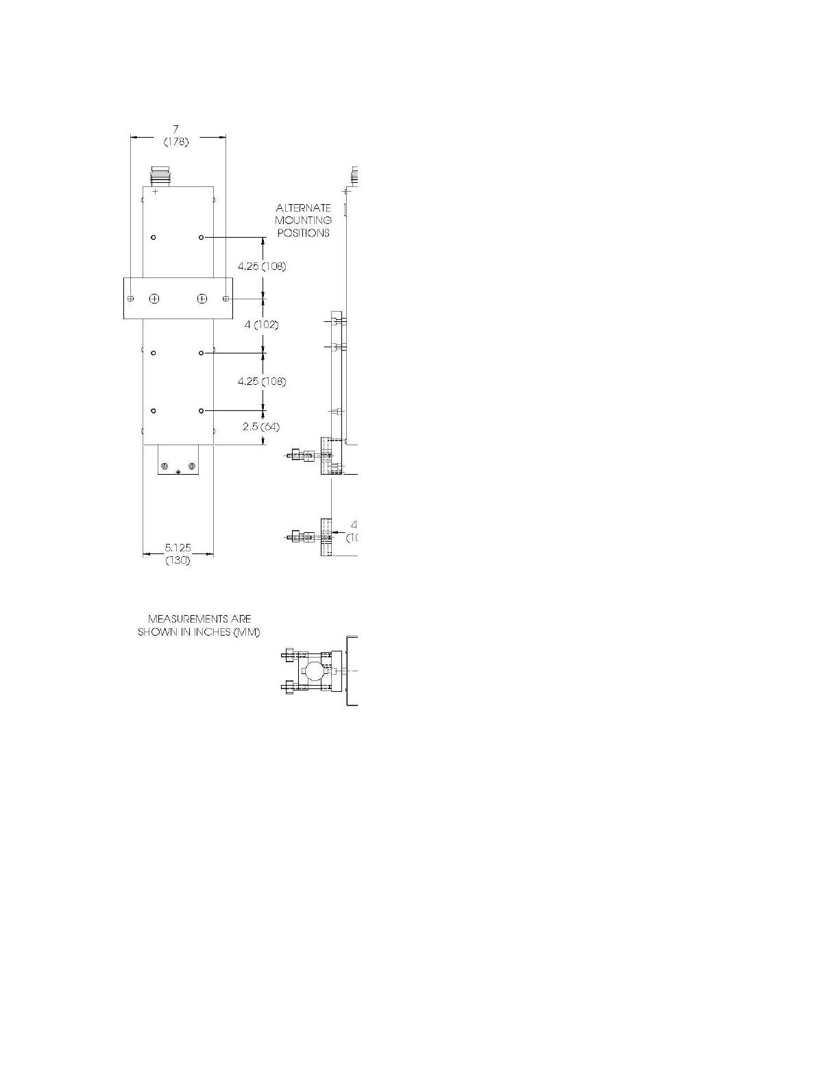
A. Actuator
Part # ALC-401-60D
The standard actuator (supplied with a
standard system) has a stroke length of
6” (150 mm). There alternative stroke
lengths of 12” (300 mm), 4” (100 mm),
and 1” (25.4 mm).
Drive: Recirculating Ball Screw
Mechanism: Linear Guideways
Mounting Holes: 2 x 13/32” (10 mm)
diameter
Mounting Positions: Four positions
See drawing
Torch Holder: Universal vee-clamp type
Torch Diameters: 3/4” to 1½” (19 to
38 mm) Diameters
Weight Capacity: 40 lb (18 kg) at the
centerline of the torch-holder
Max. Drive Speed: 30 IPM (750 mm/min)
Overall Dimensions
Length: 19” (483 mm)
Width: 5.125” (130 mm)
Depth: 2.8” (71 mm)
Weight: 17 lb (7.7 kg)
9
10
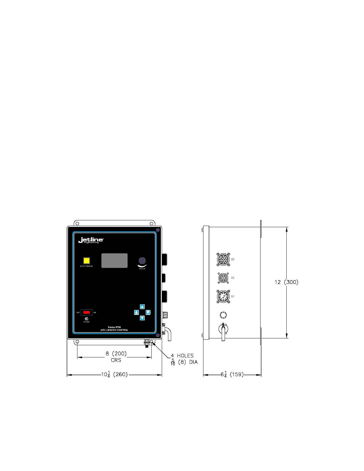
B. 9790 Control
Voltage Range: 5 to 35 DC or AC
Accuracy: +0.1% or 0.1 Volt
(Whichever is the greater)
Starting Arc Gap: 0 to 0.25” (6 mm)
Start Delay Distance: 0 to 99.9 seconds
Processor: Intel® 80C196KC, 20 MHZ.
Display: 2 x 20 Backlit LCD
Panel: Polycarbonate Overlay
Input: 120/240 VAC, 50/60 Hz
Single Phase, 200 VA
Power Cord: 6 ft (1.8 m) long
Control Wgt: 24 lb (11 kg)
Overall dimensions shown in drawing below.

11

12
SECTION IV
COMPONENTS
The ALC-701 Arc Length Control system is designed to maintain a consistent arc length during the GTAW
(TIG) and Plasma (PAW) welding processes. This is achieved by means of a closed-loop servo system. The
welding voltage is sensed and sent to the control which analyzes it, compares it with the reference signal
(the desired arc voltage which has been entered into the program) and then sends commands to cause the
drive motor to extend or retract the actuator. The actuator carries the welding torch whose position
relative to the part being welded is therefore adjusted.
The complete system consists of the following elements:
9790 Control
ALC-401-60D Actuator, with standard 6” (150 mm) stroke
ALC-401-CAB Actuator Cable
Optional items include:
ALC-CH1A Actuator, with 1” (25 mm) stroke
ALC-CH4A Actuator, with 4: (100 mm) stroke
ALC-401-60D-12 Actuator, with 12” (300 mm) stroke
ALC-401-CAB-XX (“XX” represents the cable length in feet; maximum 75 ft (23 m)
9700S1-ALC-3 Cable to connect to 9700T travel control; 3 ft (1 m) long
A. Control
The 9790 control is enclosed in a dust-tight enclosure with a hinged door. Connections are made using
three Amphenol® connectors:
S1 Connector — Actuator cable
S2 Connector — Remote Pendant cable
S3 Connector — Cable to auxiliary controls
A 6 ft (1.8 m) power cable is provided. The control accepts input voltages of 115VAC +10% or 230VAC +10%.
The control is microprocessor based, this provides enhanced operation and ease of use. Instructions are
entered and messages are displayed on the control’s LCD display. In addition to the display, the front panel
overlay incorporates touch pads and an encoder knob to select and enter information.
The control has three modes of operation:

13
Operator Mode: This is the mode which is active whenever the unit is switched on. In this mode, the
operator can change the desired arc voltage as well as being able to set sensitivity and select manual/auto
mode.
Set-up Mode: When this mode is selected, it is possible for a supervisor to select and adjust certain
parameters, such as jog speeds.
Calibration Mode: This mode is used whenever it is necessary to check the unit’s calibration or to make
other significant changes.
B. Actuator
Actuators are available in several stroke lengths.
6” (150 mm), standard
12” (300 mm)
4” (100 mm), compact
1” (25.4 mm), compact
The drive unit consists of a torch slide mechanism which rides on two linear guide rails. Motion is imparted
through a ball screw and nut driven by a geared DC servo motor. The use of recirculating ball linear bearings
results in extremely smooth movement with high sensitivity and responsiveness.
The actuator mechanism is protected by a metal cover with dust protection for the moving torch slide. At
the end of the torch slide, a torch holder is provided suitable for the securing of a wide range of different
style torches. A switch is mounted at the top of the actuator, this permits the operator to manually jog the
torch up or down prior to welding.
A mounting plate is provided at the rear of the actuator to secure the unit to the welding fixture. The
mounting plate can be repositioned vertically on the actuator. This facility provides a convenient way of
positioning the actuator relative to the fixture and the part to be welded.
Voltage sensing leads are provided, these connect to a filter circuit within the actuator mechanism. The
purpose of the filter circuit is to protect the actuator and control from the effects of high voltage and high
frequency signals.
C. Actuator Cable
The standard actuator connection cable is 10 ft (3 m) long and fitted with Amphenol® connectors at both
ends. Because of the unique design of the system, it is possible to mount the control up to 75 ft (23 m) away
from the actuator. Miller Welding Automation can provide special length cables. If it is desired to make
these yourself, it will be necessary to use the following:
Actuator Connector: 3106A-20-33S
Cord Grip: 97-3057-1012-1

14
Control Connector: 3106A-20-33P
Cord Grip: 97-3057-1012-1
Cable: 18ga, 6 pairs, Shielded
15
SECTION V
INSTALLATION AND SETUP
On receipt of the equipment, carefully check to ensure that there is no damage caused by shipping or
incorrect handling.
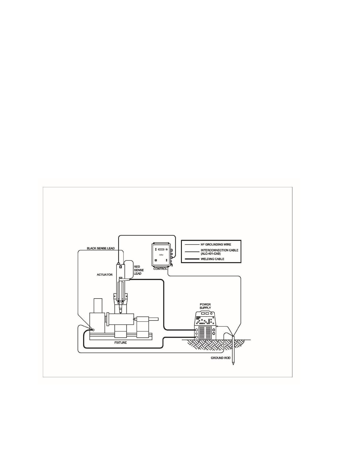
Correct installation of the system will ensure efficient, trouble-free operation. Although the equipment has
been designed and manufactured to operate within a GTAW (TIG) or Plasma (PAW) welding environment, it
is still very important to pay attention to its installation, especially to adequate grounding and
interconnection.
The drawing below shows the required interconnection for a typical installation.
The equipment should be installed as follows:
/