Page is loading ...

Form Number 0560946015 REV04
Date: 02 / 2 5/ 11
®
B4 Heavy Duty Lift Assembly
m3 CAN Plasma System
Instruction Manual

BE SURE THIS INFORMATION REACHES THE OPERATOR.
YOU CAN GET EXTRA COPIES THROUGH YOUR SUPPLIER.
These INSTRUCTIONS are for experienced operators; if you are not fully familiar with the
principles of operation and safe practices for arc welding and cutting equipment, we urge
you to read booklet “Precautions and Safe Practices for Arc Welding, Cutting, and
Gouging” (Form 52-529). Do NOT permit untrained persons to install, operate, or maintain
this equipment. Do NOT attempt to install or operate this equipment until you have read
and fully understand these instructions. If you do not fully understand these instructions,
contact your supplier for further information. Be sure to read Safety Precautions before
installing or operating this equipment.
CAUTION
This equipment will perform in conformity with the description thereof contained in this manual and accompa-
nying labels and/or inserts when installed, operated, maintained and repaired in accordance with the instruc-
tions provided. This equipment must be checked periodically. Malfunctioning or poorly maintained equipment
should not be used. Parts that are broken, missing, worn, distorted or contaminated should be replaced imme-
diately. Should such repair or replacement become necessary, the manufacturer recommends that a telephone
or written request for service advice be made to the Authorized Distributor from whom it was purchased.
This equipment or any of its parts should not be altered without the prior written approval of the manufacturer.
The user of this equipment shall have the sole responsibility for any malfunction which results from improper
use, faulty maintenance, damage, improper repair or alteration by anyone other than the manufacturer or a ser-
vice facility designated by the manufacturer.
USER RESPONSIBILITY
READ AND UNDERSTAND THE INSTRUCTION MANUAL BEFORE INSTALLING OR OPERATING.
PROTECT YOURSELF AND OTHERS!

1
B4-200 Plasma Lift Assembly
Contents
Safety
Precautions ������������������������������������������������������������������������������������������������������������������������������������������������������������������� 3
Enclosure Class ������������������������������������������������������������������������������������������������������������������������������������������������������������� 4
General Safety Recommendations ��������������������������������������������������������������������������������������������������������������������������� 5
Description
Introduction ������������������������������������������������������������������������������������������������������������������������������������������������������������������ 7
Major Components - B4 Lift ��������������������������������������������������������������������������������������������������������������������������������������� 8
Installation
Mounting ���������������������������������������������������������������������������������������������������������������������������������������������������������������������� 9
Electrical Interfacing ������������������������������������������������������������������������������������������������������������������������������������������������� 10
Station Grounding ����������������������������������������������������������������������������������������������������������������������������������������������������� 13
Maintenance
Preventative Maintenance Schedule ���������������������������������������������������������������������������������������������������������������������� 14
Daily ������������������������������������������������������������������������������������������������������������������������������������������������������������������������������������������������� 14
Weekly �������������������������������������������������������������������������������������������������������������������������������������������������������������������������������������������� 15
Monthly ������������������������������������������������������������������������������������������������������������������������������������������������������������������������������������������ 15
Semi-Annually ������������������������������������������������������������������������������������������������������������������������������������������������������������������������������ 15
Maintenance Procedures
B4-200 Lift ������������������������������������������������������������������������������������������������������������������������������������������������������������������� 17
Introduction ���������������������������������������������������������������������������������������������������������������������������������������������������������������������������������� 17
Lift Cleaning and Lubrication ������������������������������������������������������������������������������������������������������������������������������������������������� 17
B4 Lift Part Removal and Replacement ������������������������������������������������������������������������������������������������������������������������������� 19

2
B4-200 Plasma Lift Assembly
Omni Crash Protection ��������������������������������������������������������������������������������������������������������������������������������������������� 26
Description ������������������������������������������������������������������������������������������������������������������������������������������������������������������������������������ 26
Function Description �����������������������������������������������������������������������������������������������������������������������������������������������������������������27
Replacing / Adjusting the Omni® Sensor ����������������������������������������������������������������������������������������������������������������������������28
Omni® Sensor Installation ��������������������������������������������������������������������������������������������������������������������������������������������������������29
Omni® Mechanical Alignment ������������������������������������������������������������������������������������������������������������������������������������������������32
Disassembly ���������������������������������������������������������������������������������������������������������������������������������������������������������������������������������� 33
Lubrication ������������������������������������������������������������������������������������������������������������������������������������������������������������������������������������34
Technical Descriptions and Troubleshooting
Encoder Height Control �������������������������������������������������������������������������������������������������������������������������������������������� 35
Introduction ����������������������������������������������������������������������������������������������������������������������������������������������������������������������������������35
Encoder Station Constant (STA�kon) Reference Chart ����������������������������������������������������������������������������������������������������36
Setting Station Constants using distance calculations �������������������������������������������������������������������������������������������������36
AVHC Introduction and Oset Adjustment ���������������������������������������������������������������������������������������������������������� 37
Basic B4 Lift Assembly Troubleshooting ��������������������������������������������������������������������������������������������������������������� 38
Yaskawa Junma Servopack™ Alarm Indicators ����������������������������������������������������������������������������������������������������� 39

3
B4-200 Plasma Lift Assembly
Precautions
Users of ESAB welding and plasma cutting
equipment have ultimate responsibility for ensuring
that anyone who works on or near the equipment
observes all relevant safety precautions� Safety
precautions must meet requirements that apply to
this type of welding or plasma cutting equipment�
All work must be carried out by trained personnel
well acquainted with operation of welding or
plasma cutting equipment� Incorrect operation of
equipment may lead to hazardous situations which
can result in injury to the operator and damage to
equipment� The following recommendations should
be observed in addition to standard regulations that
apply to the workplace�
Anyone who uses welding or plasma cutting
1�
equipment must be familiar with:
Proper operation�
…
Location of emergency stops� …
Designed function� …
Relevant safety precautions� …
Welding and/or plasma cutting� …
Operators must ensure that:2�
No unauthorized person within the working …
area of equipment when it is started up�
No one is unprotected when plasma arc is
…
struck�
The workplace must be:
3�
Suitable and …
Free from drafts� …
Personal safety equipment:4�
Always wear recommended personal safety …
equipment, such as safety glasses, ame proof
clothing, and safety gloves�
Do not wear loose tting items, such as
…
scarves, bracelets, rings, etc�, which could become
trapped or cause burns�
Safety

4
B4-200 Plasma Lift Assembly
General precautions:5�
Make sure return cable is connected securely� …
Work performed on high voltage equipment …
may only be carried out by a qualied
electrician�
Appropriate re extinguishing equipment
…
must be clearly marked and close at hand�
Lubrication and maintenance
… must not be
carried out on equipment during operation�
The IP code indicates the enclosure class, i�e� the
degree of protection against penetration by solid
objects or water� Protection is provided against
touch with a nger, penetration of solid objects
greater than 12mm and against spraying water up to
60 degrees from vertical� Equipment marked IP23S
may be stored, but is not intended to be used out-
side during precipitation unless sheltered�
Enclosure Class
Maximum
Tilt Allowed
15°
If equipment is placed on a surface that slopes
more than 15°, toppling over may occur.
Personal injury and/or signicant damage to
equipment is possible.
CAUTION
WELDING AND PLASMA CUTTING CAN
CAUSE INJURY TO YOURSELF AND
OTHERS. TAKE PRECAUTIONS WHEN
WELDING OR CUTTING. ASK FOR YOUR
EMPLOYER’S SAFETY PRACTICES WHICH
SHOULD BE BASED ON MANUFACTURERS’
HAZARD DATA.
WARNING

5
B4-200 Plasma Lift Assembly
ELECTRIC SHOCK - Can kill�
Ground welding or plasma cutting units in
•
accordance with applicable standards�
Do not touch live electrical parts or electrodes
•
with bare skin, wet gloves, or wet clothing�
Insulate yourself from earth ground and the
•
workpiece�
Ensure your working stance is safe�
•
FUMES AND GASES - Can be dangerous to health�
Keep your head out of the fumes�
•
Use ventilation, extraction at the arc, or both, to •
take fumes and gases away from your breathing
zone and the general area�
ARC RAYS - Can injure eyes and burn skin�
Protect your eyes and body, using correct
•
welding/plasma cutting screens and lter lens�
Wear protective clothing�
•
Protect bystanders with suitable screens or •
curtains�
FIRE HAZARD - Sparks (spatter) can cause re� Make
sure that there are no ammable materials nearby�
NOISE - Excessive noise can damage hearing�
Protect your ears, using ear protection�
•
Warn bystanders of the risk�•
MALFUNCTION - Call for expert assistance in the
event of malfunction�
General Safety
Recommendations
READ AND UNDERSTAND THE INSTRUCTION
MANUAL BEFORE INSTALLING OR OPERATING.
PROTECT YOURSELF AND OTHERS!
CAUTION

6
B4-200 Plasma Lift Assembly
To avoid personal injury and/or equipment dam-
age, lift using method and attachment points
shown below.
CAUTION

7
B4-200 Plasma Lift Assembly
Introduction
The B4-200 lift assembly provides vertical motion for
the PT-36 plasma torch, using a typical motor, screw,
and slide conguration� The motor turns an enclosed
spindle screw, which in turn raises/lowers the lifting
plate along linear rails� Directional commands given
from CNC determines direction of lift travel� Fixed
limit switches are included to prevent upper and
lower over travel�
The lift assembly also contains components
necessary to control height over work surfaces;
initial, piercing, and cornering heights are encoder-
controlled during the plasma cycle through use
of SDP/TDF les� During part production, stando
is automatically controlled by taking voltage
measurements between torch nozzle and work
surface�
Finally, the B4 lifts include an Omni Soft Touch®
assembly to protect the system during station
crashes� Proximity switches monitor torch position in
the torch holder� If the torch is jarred in any direction,
process movement will stop and an error report will
be sent to CNC� The Illustration on following page
will detail major lift components and their location�
For illustrated part breakdowns, see end section of
this manual�
Description

8
B4-200 Plasma Lift Assembly
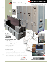
Major Components - B4 Lift
Remote Arc Starter box
Torch Bundle Guide ring
B4 Lift Mounting bracket (option)
Electrical Soft Touch box
B4 Lift Electronics Enclosure
Plasma Gas box
B4 Lift Assembly
OMNI Mounting bracket
Electrical Soft Touch wire (option)
OMNI Soft Touch® assembly
PT-36 m3C Torch
1
2
3
4
5
6
7
8
9
10
11
Technical Specications
Lift Speed:• 315 IPM [8.0m per minute]
Vertical Travel: 8.00” [200.0 mm]
•
Approximate Weight of Lift Assembly •
including torch holder: 85 lbs. [38.5 kg]
Torch Barrel Size: 85.7 mm
•
Component Tolerances•
IHS Accuracy: ± 0.5 mm …
Encoder Accuracy: ± 0.25 mm …
Voltage Accuracy: ± 1 volt …

9
B4-200 Plasma Lift Assembly
Installation
Mounting
B4 lift hole patterns are provided below to aid end
users in mounting the plasma station. An optional
plasma bracket/nut plate are available as an option;
part numbers are included in Replacement Parts
section of this manual.
B4-200 Lift Assembly dimensions
(6) M8 x 1.25 x 40
Socket Head Cap Screws
5.00”
[127.0mm]
4.13” [104.9mm]
0.49” [12.4mm]
3.64” [92.4mm]
4.47”
[113.5mm]
x6 M8x1.25 - 6H
THRU HOLES
0.53”
[13.5mm]
2.50”
[63.5mm]

10
B4-200 Plasma Lift Assembly
NOTICE
Ensure lift assembly is mounted
plumb; use a torpedo level and
adjust mounting bolts as needed.
Torpedo Level
Electrical Interfacing
After lift assembly and electrical enclosure have
been mounted, make the following electrical
connections:
Lift Input Power1� (4 pin, male_female):
connection is from control interface box AHC
Power to lift electrical enclosure SB2�
ACON cable
2� (M12, 8 pin, male_male):
connection is from control interface box CAN #
connector to lift electrical enclosure SB1�
Crash Protection cable3� (M12, 8 pin male_
female): connection is from lift electrical
enclosure SB3 to Omni® Soft Touch proximity
sensor�
NOTICE
CAN # connection used will vary
depending on your system conguration.
See System Interconnection manual (PN
0558008527) to determine your system
conguration.
m3 CAN OEM Interface Box

11
B4-200 Plasma Lift Assembly
Lift Electrical Enclosure
connection guide
SB2 - Input Power
SB1 - ACON
SB3 - Crash Protection OR
Soft Touch Interconnection
SB5 - VDR (RAS)
1
2
3
A
3
A
2
1

12
B4-200 Plasma Lift Assembly
The following connections will need to be made if
your plasma station has electrical soft touch option
installed:
Soft Touch Interconnection cable
4� (M12, 8 pin
female-female): connection is from lift electrical
enclosure SB3 to soft touch enclosure ST1�
Soft Touch Proximity cable5� (M8 female socket_
free wire end): connection is from X3 (inside
soft touch electrical enclosure) to Omni® Soft
Touch proximity sensor�
Torch Touch wire
6� (14-16AWG, in-line terminal_
torch clamp): connection is from soft touch
board X4 to torch clamping ring� Attach this
clamping ring to metal portion of PT-36 torch
body�
NOTICE
The Soft Touch Interconnection cable (#4)
will replace the Crash Protection cable (#3)
on plasma stations utilizing electrical soft
touch option.
Electrical Soft Touch Enclosure
Connection Guide
Soft touch enclosure lid was made transparent to show box detail.
9
7
8

13
B4-200 Plasma Lift Assembly
Station Grounding
Before placing the plasma station into operation,
ensure that the following grounding points are
established:
Lift Electrical Enclosure
•
Soft Touch Electrical Enclosure•
Grounding points should be fastened to bare,
unpainted metal and should measure less than 10
ohms on a digital multimeter�
Do not use star washers to establish
grounding points!
Star washers do not cut painted surfaces
adequately enough to establish ground
potential; ground surfaces should be
against bare metal.
CAUTION
DO NOT cut under water if electrical
soft touch option is installed on
your plasma station!
CAUTION

14
B4-200 Plasma Lift Assembly
Maintenance
Preventative Maintenance
Schedule
Time periods suggested below are based on average
plasma station usage� If station is employed in
a heavy usage cycle, used outdoors, or used on
a multi-torch cutting machine, suggested time
intervals should be shortened� Regularly scheduled
maintenance will signicantly increase the life and
performance of your equipment�
Daily
Wipe dust and fume buildup from lift assembly •
and components�
Check for worn or damaged cables on all lift
•
subassemblies�
Ensure all mechanical fasteners and electrical
•
connections are correct; no stripping of
hardware, connections are tight, exposed wires,
etc�
Check that lift travel limit switches are
•
functioning correctly�
Use your CNC’s station travel buttons to ensure
•
lift assembly has proper, smooth movement�
Replace any worn PT-36 torch consumables�
•
Test Omni® crash protection function; ensure •
that when plasma torch is jarred in any direction,
a crash signal appears at the CNC�
Read all instruction manual’s safety
and maintenance procedures
before beginning any preventative
maintenance!
CAUTION

15
B4-200 Plasma Lift Assembly
Weekly
Check alignment of lift assembly�•
Check Omni® proximity sensor position and •
adjust, if required�
NOTICE
Many replacement parts subject to wear
or used in preventative maintenance
schedules are available directly through
ESAB Cutting Systems.
See “Consumables and Spare Parts”
section in Replacement Parts portion of
this manual before ordering.
Monthly
Clean and lubricate slide assembly (see •
procedure on page 18)�
Check alignment, clean and lubricate Omni®
•
crash assembly (see procedure on page26)�
Semi-Annually
Repeat all previous maintenance procedures�•
Consider calling your ESAB Service •
Representative to schedule an semi-annual
station inspection�

16
B4-200 Plasma Lift Assembly
Maintenance Procedures
The following section contains maintenance
procedures for the lift assembly and components�
This section will provide some basic troubleshooting
methods to return your station to correct operation�
Only qualied maintenance personnel should utilize
these procedures�

17
B4-200 Plasma Lift Assembly
B4-200 Lift
In order for B4 slide assemblies to perform at
optimum levels, it will need to be inspected, cleaned
and lubricated on a weekly basis� The following
procedure will detail steps necessary to correctly
clean and lubricate your slide assembly:
Remove (3) cap screws attaching front cover�
1�
Run lift to lower limit and wipe ball screw with 2�
a clean, dry cloth� Apply lithium based NGLI 2
grease or softer grease directly to screw�
Introduction
The B4-200 heavy duty vertical lift employs an
enclosed motor that turns a ball screw� This is made
possible by using a pair linear bearing blocks and a
drive belt, which lowers or raises the lifter assembly
along linear rails� Direction depends on commands
received form the CNC� The illustration at left is the
B4 lift with some parts hidden for clarity� The three
grease ttings can be accessed without removing lift
covers�
Lift Cleaning and Lubrication
Spindle Ball screw
Spindle Ball nut
Upper Limit switch and cam
Precision Linear rail (2)
Linear Bearing blocks (2)
Lower Limit switch
Lift Electronics Enclosure
Timing belt
Motor / Encoder
Lifter Assembly w/ bellows
1
2
3
4
5
6
7
8
9
10

18
B4-200 Plasma Lift Assembly
Do not use solvents or solvent-based
lubricant to clean ball screw; this can
remove lubricant from sealed linear
bearing blocks.
CAUTION
Run lift to upper limit�3�
Apply same grease to three zerk ttings; apply 4�
0�1 ounce (3cc) or half pump of a grease gun to
each tting�
NOTICE
Lift covers do not need to be removed to
access grease ttings.
See illustration above for tting locations.
Reinstall front cover to lift assembly�5�
Screw Nut
zerk tting
Linear Bearing
zerk ttings
/