
POWERTRONIX SpA reserves the right to modify this document without any notice
Pag. 1 di 41
R&D
–
PROCEDURA START
-
UP DT 0419
–
E02
USER MANUAL
VELA 50-60 kVA
Document : DT0419 English - Ptx
Revision Date Checked by Approved by
00 01-10-2007 01-10-2007 Riccardo G.
Darek A.
01-10-2007 Andrea G.
01 22-10-2007 22-10-2007 Gabriele P. 22-10-2007 Andrea G.
02 10/12/2008 10/12/2008 Andrea P. 10/12/2008 Andrea G.
POWERTRONIX
UNINTERRUPTIBLE POWER SUPPLY

POWERTRONIX SpA reserves the right to modify this document without any notice
Pag. 2 di 41
R&D
–
PROCEDURA START
-
UP DT 0419
–
E02
INDEX
INDEX ................................................................................................................................................................................2
1 UPS GENERAL INFO..............................................................................................................................................4
1.1 UPS GENERAL DESCRIPTION.......................................................................................................................4
1.1.1 UPS APPLICATIONS ...............................................................................................................................4
1.1.2 POWER AND AUTONOMY .....................................................................................................................4
1.1.3 SAFETY AND SIMPLICITY OF USE ......................................................................................................4
1.2 CONFIGURATIONS AND OPTIONAL EQUIPMENTS...................................................................................5
1.2.1 BASE CONFIGURATION.........................................................................................................................5
1.2.2 BATTERY CABINET.................................................................................................................................5
1.2.3 TRANSFORMER CABINET.....................................................................................................................5
1.2.4 CIRCUITS FOR REMOTE COMMUNICATION .....................................................................................6
1.2.5 UPS MANAGEMENT SOFTWARE.........................................................................................................6
1.3 REMOTE PANEL................................................................................................................................................7
1.4 REMOTE E.P.O. PUSHBUTTON .....................................................................................................................7
1.5 OPERATING THEORY......................................................................................................................................8
1.5.1 UPS BLOCK DIAGRAM ...........................................................................................................................8
1.5.2 INPUT STAGE, POWER MODULE AND OUTPUT STAGE ................................................................8
1.5.3 LOGIC AND AUXILIARY CIRCUITS.......................................................................................................9
1.5.4 BATTERIES...............................................................................................................................................9
1.5.5 MANUAL BY-PASS...................................................................................................................................9
1.5.6 FRONT PANEL .........................................................................................................................................9
2 INSTALLATION INSTRUCTIONS........................................................................................................................10
2.1 GENERAL INFORMATIONS...........................................................................................................................10
2.2 RECEPTION AND IDENTIFICATION.............................................................................................................10
2.3 STORAGE.........................................................................................................................................................10
2.4 UPS POSITIONING..........................................................................................................................................11
2.5 ROOM SPECIFICATIONS...............................................................................................................................13
2.6 CONNECTIONS AND LAYOUT TO THE MAINS .........................................................................................14
2.7 UPS AUX CONNECTIONS .............................................................................................................................17
2.8 REMOTE COMMUNICATION BOARD ..........................................................................................................18
2.8.1 REMOTE PANEL (OPTIONAL).............................................................................................................19
2.8.2 UPS MANAGEMENT SOFTWARE.......................................................................................................20
2.8.3 REMOTE E.P.O. PUSHBUTTON..........................................................................................................20
2.9 EARTH CONNECTION....................................................................................................................................20
3 CONTROL PANEL.................................................................................................................................................21
3.1 INTRODUCTION ..............................................................................................................................................21
3.2 LCD CONTROL PANEL...................................................................................................................................22
3.3 UPS STATES AND ALARMS VISUALIZATION............................................................................................23
3.4 MEASUREMENTS ...........................................................................................................................................24
3.5 UPS IN FAULT CONDITIONS.........................................................................................................................25
3.6 MENU 1: UPS COMMANDS ...........................................................................................................................26
3.7 MENU 2 : EVENTS HISTORY.........................................................................................................................26
3.8 MENU 3 : OPERATIVE LANGUAGE..............................................................................................................26
3.9 MENU 4: CLOCK..............................................................................................................................................26
3.10 MENU 5 : UPS CONFIGURATION ............................................................................................................26

POWERTRONIX SpA reserves the right to modify this document without any notice
Pag. 3 di 41
R&D
–
PROCEDURA START
-
UP DT 0419
–
E02
4 INSTRUCTIONS FOR THE UPS ..........................................................................................................................27
4.1 INTRODUCTION ..............................................................................................................................................27
4.2 POWER SWITCHES........................................................................................................................................27
4.3 UPS START-UP PROCEDURE......................................................................................................................29
4.4 INSTRUCTIONS FOR SWITCHING SYSTEM TO MANUAL BY-PASS MODE ........................................30
4.5 INSTRUCTIONS FOR RETURN FROM MANUAL BY-PASS MODE TO NORMAL OPERATION .........31
4.6 INSTRUCTIONS FOR COMPLETE SHUTDOWN OF THE UPS................................................................32
4.7 E.P.O. (EMERGENCY POWER OFF) STOP ................................................................................................32
4.8 INSTRUCTIONS FOR TURNING ON THE UPS IN POWER SAVE MODE ..............................................33
4.9 INSTRUCTIONS FOR SWITCHING SYSTEM IN POWER SAVE MODE TO MANUAL BYPASS MODE
34
4.10 INSTRUCTIONS FOR RETURN FROM MANUAL BY-PASS MODE TO NORMAL OPERATION IN
POWER SAVE MODE................................................................................................................................................35
4.11 INSTRUCTIONS FOR COMPLETELY SHUTTING OFF THE UPS IN POWER SAVE MODE...........36
4.12 MANAGING THE UPS BATTERY..............................................................................................................37
5 UPS IN PARALLEL................................................................................................................................................38
5.1 SYSTEM SET-UP.............................................................................................................................................38
6 TROUBLESHOOTING...........................................................................................................................................39
6.1 GENERAL ALARMS.........................................................................................................................................39
6.2 CASE OF THE FIRE ........................................................................................................................................40
6.3 FAULTS RELATED TO THE LOAD................................................................................................................40
7 SCHEDULED MAINTENANCE.............................................................................................................................41
7.1 ANNUAL MAINTENANCE...............................................................................................................................41
7.1 SCHEDULED COMPONENTS REPLACEMENT..........................................................................................41

POWERTRONIX SpA reserves the right to modify this document without any notice
Pag. 4 di 41
R&D
–
PROCEDURA START
-
UP DT 0419
–
E02
1 UPS GENERAL INFO
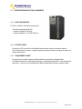
1.1 UPS GENERAL DESCRIPTION
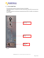
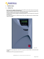
These UPS families have the compact construction, with the outer metal frame and the electronic circuits
and power components inside. All user accessible elements an the control panel are placed on the front
side.
The top and side covers can be removed, giving an access to the internal part of the UPS for the service or
maintenance purposes.
The front side of all units contains the user interface panel useful for monitoring, maintenance and control.
The UPS has a air forced cooling system, the air is going out to the back side of the cabinet.
The terminal block for the electrical connection to the mains, reserve, load, external batteries, and the main
circuits breakers, are located on the front side of the unit.
1.1.1 UPS APPLICATIONS
The new UPS family was designed to provide stabilized and filtered power, especially for supplying
sophisticated and sensitive electronic devices (i.e. for data processing systems). Vela UPSes can be used
to supply electronic systems of medical centers, police stations, motorway tunnels, broadcasting stations,
banks, technical and administrative offices, requiring the power source free from voltage and frequency
variations.
1.1.2 POWER AND AUTONOMY
Thanks to its modular design, the UPS models are available with rated power from 50kVA to 65kVA
For all the size of the family are not available the internal battery, an or more external battery modules can
be used to increase the UPS autonomy.
1.1.3 SAFETY AND SIMPLICITY OF USE
All the UPS elements available for user daily maintenance are insulated and disconnected from hazardous
voltages.
Control of the overload and excessive temperatures guarantees the immediate and most suitable
intervention in the case when one of these conditions occurs during operation.
The operator can view the UPS status on the front panel and perform shut down or switching operations
easily (see chap. 3)
The unit is provided with the E.P.O. (Emergency Power Off). This function is activated by pressing the
button located on the front panel.
A remote E.P.O (optional) switch can be connected to UPS to provide remote emergency power off action.
The UPS state can be easily monitored with the personal computer and an interacting program (optional) or
through the remote panel (optional), especially when the UPS is installed in unmonitored areas. Refer to
the chapters 1.2.5 - 1.2.6.

POWERTRONIX SpA reserves the right to modify this document without any notice
Pag. 5 di 41
R&D
–
PROCEDURA START
-
UP DT 0419
–
E02
1.2 CONFIGURATIONS AND OPTIONAL EQUIPMENTS
1.2.1 BASE CONFIGURATION
The UPS is available in the following configurations:
- Six pulses configuration 50-60 kVA
- 12 pulses configuration 50-60 kVA
- 12 pulses configuration + low THD 50-60 kVA
1.2.2 BATTERY CABINET
If required, the UPS can be furnish with additional optional battery cabinet to increase the autonomy
All the batteries will be mounted in a separate cabinet with opportune dimensions complete of power circuit
breaker and protections.
1.2.3 TRANSFORMER CABINET
If required, there is available a galvanic isolating transformer, positioned in a separate cabinet.
The standard transformer is three-phase/three-phase (or single-phase/single-phase or three-phase/single-
phase) with 1:1 ratio, but it can be supplied with a different transformation ratio upon customer request.

POWERTRONIX SpA reserves the right to modify this document without any notice
Pag. 6 di 41
R&D
–
PROCEDURA START
-
UP DT 0419
–
E02
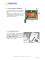
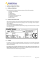
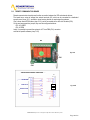
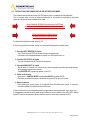
1.2.4 CIRCUITS FOR REMOTE COMMUNICATION
Remote communication board (the code CS0118),
gives possibility of monitoring and communicating with
UPS.
Monitoring can be implemented with the PC and
dedicated software or through a remote panel. There
are also voltage free contacts available on the terminal
board M1 (more info at page 18).
1.2.5 UPS MANAGEMENT SOFTWARE
The “UPS MANAGEMENT” Generex communication
software allows interaction between UPS and PC or
the network based on Windows, Win-NT, Novell, OS2,
Dec, and Linux operating systems.
The software is used to monitor and control
parameters of one or more UPS units supplying the
network (more info at page 22)
CN1
CN3
CN4
M1

POWERTRONIX SpA reserves the right to modify this document without any notice
Pag. 7 di 41
R&D
–
PROCEDURA START
-
UP DT 0419
–
E02
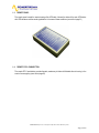
1.3 REMOTE PANEL
The remote panel is used for remote viewing of the UPS state; it shows the status of the main UPS blocks
with LED indicators and the sound signalization in the case of alarm conditions (more info at page 21)
1.4 REMOTE E.P.O. PUSHBUTTON
The remote E.P.O push-button provides the safe, remote way to fast and full disable the unit running in the
event of an emergency (more info at page 22)

POWERTRONIX SpA reserves the right to modify this document without any notice
Pag. 8 di 41
R&D
–
PROCEDURA START
-
UP DT 0419
–
E02
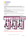
1.5 OPERATING THEORY
The UPS described here is an on-line dual conversion type UPS, with automatic by-pass in compliance
with European standard EN62040-1-2. This UPS performs the dual conversion of the incoming voltage
continuously and without interruption.
The absence of direct connection between mains and load eliminates the possibility of carrying
disturbances from mains to the load. The dual conversion technique guarantees to the load delivering
energy regulated both in voltage and frequency - thus ideal for the operation of professional applications.
When the input voltage exceeds the allowed range or - more simply - is not present, the load is supplied by
energy transferred from the batteries.
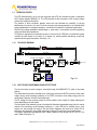
The system is supplied with an automatic by-pass; in the event of the UPS fault or overload the by-pass
connects the load directly to the mains via a reserve line, making possible maintaining normal load
operation without supply interruptions. See the fig. 1.5.1
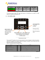
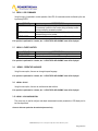
1.5.1 UPS BLOCK DIAGRAM
1.5.2 INPUT STAGE, POWER MODULE AND OUTPUT STAGE
From the input bars the mains voltage is connected through the MAINS INPUT l1 switch to the power
module.
The rectifier-step-up converter controlled by the control logic, performs the AC/DC conversion of the mains
voltage (during normal operating conditions) or the DC/DC conversion of the battery energy when the
mains power is absent or not within the allowed range.
The DC voltage from the converter powers the inverter module, which creates AC voltage, adjusting the
current depending on the load needs.
The last module is the automatic by-pass. It transfers the filtered and regenerated energy from the inverter
module to the load during normal operating conditions, or - when UPS fault or overload occurs - from
reserve line, still providing the energy to the load. When disappears the cause which forced UPS to
switching to the reserve line, the by-pass automatically switches the load to the inverter power source.
The filtered, regenerated and stabilized mains voltage supplies the load through the UPS OUTPUT (l4)
switch. Refer to the figure 1.5.1
RESERVE LINERESERVE LINE
MANUAL BY-PASS MANUAL BY-PASS
MAINS INPUT
MANUAL BY-PASS
OUTPUT-LOAD
RECTIFIER - STEP UP CONVERTER INVERTER STATIC SWITCH
BATTERY CAHRGER
3PH + N + PE
3PH + N + PE
I1
I2
I3
I4
BATTERY CABINET
Fig. 1.5.1

POWERTRONIX SpA reserves the right to modify this document without any notice
Pag. 9 di 41
R&D
–
PROCEDURA START
-
UP DT 0419
–
E02
1.5.3 LOGIC AND AUXILIARY CIRCUITS
The control logic occupies the separate board (CS0119) and represents the “intelligence” of the UPS.
It manages operations of the step-up converter, inverter and by-pass, based on feedback signals taken
from the power module. The control logic also manages the other three boards: the battery charger,
auxiliary power supply and signal interface.
The battery charger handles recharging of the outside batteries connected to the UPS.
The signal interface receives the signals from the control logic and converts them into the protocol required
by the front panel of the UPS and also the relays board. Going backwards, the selected commands from
the front panel (automatic by-pass forcing) and/or relay board (EPO) are sent from the signal interface to
the control logic which interprets them and performs desired operation – like switch on/off inverter or shut
down the unit.
The signal interface, except controlling standard relays board, can also control another (optional) one.
The auxiliary power supply supplies all the boards and electronic components in the UPS.
1.5.4 BATTERIES
The battery set provides energy to the system when the input mains is out of the allowed range
or not present; in all other cases batteries are constantly recharged by the charger module. In this way the
batteries are always ready for use when required.
1.5.5 MANUAL BY-PASS
The manual by-pass is useful in the situations, when it is necessary to disable the UPS and keep the load
supplied by the mains (i.e.: UPS stopped, fault, etc.). can be activated with using the MANUAL BY-PASS
(l3) switch, located in the front part of the UPS (refer to chapter 4). In normal operating conditions this
circuit breaker remains in rest position, protected with the mechanical lock (the padlock).
1.5.6 FRONT PANEL
The UPS can be managed via the front panel. Using the panel it is possible to execute the commands,
display states and measurements and reset the alarm circuits.
The panel is equipped with an LCD screen used to display the operating status of the UPS, the load and all
types of measurement (see chapter 3)

POWERTRONIX SpA reserves the right to modify this document without any notice
Pag. 10 di 41
R&D
–
PROCEDURA START
-
UP DT 0419
–
E02
2 INSTALLATION INSTRUCTIONS
2.1 GENERAL INFORMATIONS
This chapter describes the system installation procedures and lists the following subjects:
2.2 Reception and identification
2.3 Storage
2.4 UPS positioning
2.5 Room specifications
2.6 Arrangement and connection to mains
2.7 UPS Auxiliary connections
2.8 Earth connection
2.2 RECEPTION AND IDENTIFICATION
After removing the packing, visually inspect inside and outside the UPS and battery module (if included) to
check for any damage that could occur during shipping. If there is any damage, inform the shipper or
retailer immediately.
Check the supplied material against the packing slip.
The machine has an adhesive identification plate indicating the type, power and serial number; it is located
on the right door (fig.2.2).
2.3 STORAGE
If the system is not going to be installed immediately it must be stored in an environment with adequate
protection against excessive humidity and sources of extreme heat (from +5 to +40°C, humidity less than
95% without condensation).
If the battery module is supplied, also make sure that no more than 6 months pass between one
battery recharge and the next. Once this period of time has elapsed, temporarily hook the UPS up to the
mains and run it for the time needed to recharge the batteries.
Fig. 2.2

POWERTRONIX SpA reserves the right to modify this document without any notice
Pag. 11 di 41
R&D
–
PROCEDURA START
-
UP DT 0419
–
E02
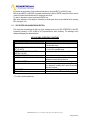
2.4 UPS POSITIONING
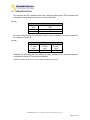
All the size and configurations are developed in the same cabinet with the characteristics described in the
tables 2.4a-b-c below:
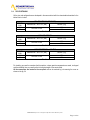
6 PULSES VERSION (STANDARD)
POWER
(kVA) DIMENSIONS W x D x H (mm) WEIGHT (Kg)
50 196
60 530 x 950 x 1220 196
Tab. 2.4a
12 PULSES VERSION
POWER
(kVA) DIMENSIONS W x D x H (mm) WEIGHT (Kg)
50 330
60 530 x 950 x 1220 330
Tab. 2.4b
12 PULSES VERSION + LOW THD
POWER
(kVA) DIMENSIONS W x D x H (mm) WEIGHT (Kg)
50 370
60 530 x 950 x 1220 370
Tab. 2.4c
For handling you need to remember that the machine, unless special arrangements are made, is shipped
and thus handled, thus you need to refer to the higher weight of the version used.
All the connections are located in the rear panel and can be reached by just removing the cover as
shown on the fig. 2.4

POWERTRONIX SpA reserves the right to modify this document without any notice
Pag. 12 di 41
R&D
–
PROCEDURA START
-
UP DT 0419
–
E02
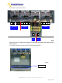
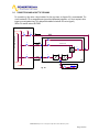
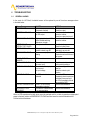
Fig. 2.4 shows the external connections.
Looking at the front, the cables input is located on the lower side and accessible after opening the main
UPS door (fig.2.5)
For the cables connection according to the UPS configuration refer to fig.2.4
fig. 2.4
Fig. 2.5
CABLES INPUT
L1
INGRESSO
PRINCIPALE
INGRESSO
RISERVA
USCITA
+
-
L2
L3
N
L1
L2
L3
N
L1
L2
L3
N
+
BATT
-
BATT

POWERTRONIX SpA reserves the right to modify this document without any notice
Pag. 13 di 41
R&D
–
PROCEDURA START
-
UP DT 0419
–
E02
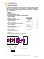
2.5 ROOM SPECIFICATIONS
The room where the UPS is installed must be clean; it must have pollution class 2 (CEI) and must be able
to dissipate the heat produced by the machine, as shown in table 2.5a.
Tab. 2.5a
Power
Rated power
(kVA)
Power dissipation
(kW)
50 4
60 4.8
For correct battery ventilation, the room must be able to ensure an exchange of air equal or greater than
the value shown in table 2.5b.
Tab. 2.5b
Remember that the average life of the batteries is closely correlated with the operating temperature;
a temperature of around 20°C is normally recommended.
(when the temperature rises above 20°, for each 10° higher the battery life drops by 50%)
Air exchange only for battery hydrogen
Air exchange for
15’ auton.
(m3/h)
Air exchange for
30’ auton.
(m3/h)
Air exchange for
1h auton.
(m3/h)
10 19 32

POWERTRONIX SpA reserves the right to modify this document without any notice
Pag. 14 di 41
R&D
–
PROCEDURA START
-
UP DT 0419
–
E02
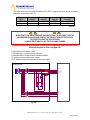
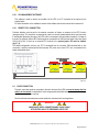
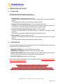
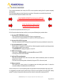
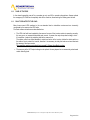
2.6 CONNECTIONS AND LAYOUT TO THE MAINS
For connection to the mains a layout solution like the one shown in diagram 2.6 is recommended. The
circuit breakers B-C-D are magnetothermic type without differential protection, or if this is required, with a
triggering current greater than 0.3A, delayed and suitable for load with DC current (type A).
Switch A is used as external BY-PASS.
Load
Standard mains
Standard mains
Standard reserve
Standard reserve
BT1
BATTERY CABINET
I
BATTERY1
I1
INPUT
I2
RESERVE
I3
BY-PASS
I4
OUT
C
D
B
BY-PASS
=
=
RESERVE LINE
UPS
DISTRIBUTION PANEL
fig. 2.6
A

POWERTRONIX SpA reserves the right to modify this document without any notice
Pag. 15 di 41
R&D
–
PROCEDURA START
-
UP DT 0419
–
E02
The control parts and all the power connections of the UPS in question need to be able to permanently
support the current shown in tab. 2.6
UPS power
(kVA)
Mains input
Imax (A)
Reserve input
Imax (A)
User outputs
Imax (A)
Battery discharge
current (A)
50 75 76 76 140
60 90 91 91 166
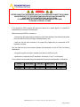
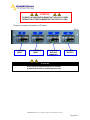
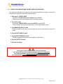
WARNING !!
IN ADDITION TO THE CIRCUIT BREAKER AND PROTECTION IT IS ADVISABLE TO SET UP
AN APPROPRIATE CHANGE-OVER CONTACT ON THE INPUT SIDE OUTSIDE THE UPS
TO PROTECT AGAINST VOLTAGE RETURNS,
AS INDICATED IN TABLE 2.6 AND THE FOLLOWING DRAWING:
If necessary for the Vela series 50-60kVA, a system against voltage return needs to be created in the
UPS distribution panel as shown in diagram 2.6b
A: general mains circuit breaker / switch
C: automatic switch or at least a fuse for the mains
B: automatic switch or at least a fuse for the reserve network
K3: protection contactor against return voltage
K1-K2: additional relays on the change-over contact coil supply
UPS
L1-RESERVE
L2-RESERVE
L3-RESERVE
NEUTRAL
L1-MAINS
L2-MAINS
L3-MAINS
NEUTRAL
A B
C
L1
L2
L3
NEUT
K2K1
K3
DISTRIBUTION PANEL
Tab. 2.6
fig. 2.6b

POWERTRONIX SpA reserves the right to modify this document without any notice
Pag. 16 di 41
R&D
–
PROCEDURA START
-
UP DT 0419
–
E02
WARNING !!
BEFORE CONNECTING THE UPS MAKE SURE THAT THE LINES WHICH CONNECT THE UPS MAINS
AND RESERVE INPUT TO THE DISTRIBUTION PANEL ARE OPEN AND DISCONNECTED.
MAKE SURE THAT THE BATTERY PANEL SWITCH IS OPEN.
PUT WARNING SIGNS ON THE DISTRIBUTION PANEL AND BATTERY PANEL
TO PREVENT ACCIDENTAL ACTIONS.
If not required, the UPS is supplied with mains and reserve line in parallel (fig.2.6c). It is possible to
separate them by removing the connecting bars.
Before connecting the UPS it is necessary to:
- make sure that the mains voltage and frequency match those indicated on the adhesive plate located
on the rear side of the UPS (input voltage, operating frequency, etc.);
- make sure that the earth connection of the system fully complies with the requirements of IEC
standards or local laws.
After that install four pole circuit breakers upstream and downstream from the UPS with the following
specifications:
- rating equal or greater than what is indicated on the label on the UPS rear (kVA);
- specifications in compliance with IEC standards or local laws for “Curve C” circuit breakers.
The connections must be created using a flex cables with the section as recommended in a table below
P (KVA) Ø A.C. (mm2) I A.C. (A) Ø D.C. (mm2) I D.C. (A)
50 (KVA) 16 76 50 140
60 (KVA) 25 91 70 166

POWERTRONIX SpA reserves the right to modify this document without any notice
Pag. 17 di 41
R&D
–
PROCEDURA START
-
UP DT 0419
–
E02
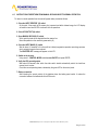
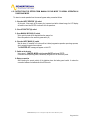
2.7 UPS AUX CONNECTIONS
The communications boards are mounted over the power circuits breakers.
The standard equipment is composed of the remote communication board (CS0118) and set-up for the
SNMP board.
It is possible to connect a second (optional) communication board (CS0118) in addition to the standard as
shown in a fig.2.7
Communication board
(cap. 2.7.1)
Communication board
Optional
SNMP board
Optional
fig. 2.7

POWERTRONIX SpA reserves the right to modify this document without any notice
Pag. 18 di 41
R&D
–
PROCEDURA START
-
UP DT 0419
–
E02
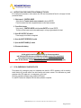
2.8 REMOTE COMMUNICATION BOARD
Remote communication board is used to allow connection between the UPS and external devices.
The board has a series of voltage free contact terminals (M1) which can be connected to a dedicated
synoptic panel (chap. 2.8.1), acoustic or visual warning devices or remote signaling systems.
One or more remote EPO buttons (chap. 2.8.3) can be connected via the other two contacts (CN3).
On the card are present two jumper, they must be configured as below :
JP5 CLOSED
JP6 OPEN
Lastly, it is possible to connect the system to a PC via a DB9 (CN1) connector
and use the specific software (chap. 2.8.2)
fig. 2.8a
fig. 2.8b
CN3
CN1
M1
JP5
CN1
CN3
J
P6
INVERTER ON
MANUAL BYPASS
MAINS NOT OK
LOW BATTERY
RELAYS BOARD EXTERNAL CONNECTI
ONS

POWERTRONIX SpA reserves the right to modify this document without any notice
Pag. 19 di 41
R&D
–
PROCEDURA START
-
UP DT 0419
–
E02
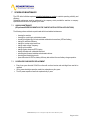
2.8.1 REMOTE PANEL (OPTIONAL)
Remote panel is connected to the UPS via the terminal board M1 located on the remote communication
board (CS0118)(connection diagram fig. 2.8b). This device is used for remote monitoring of the main UPS
blocks, the status of the main blocks is represented through LED, and there is also an acoustic alarm,
which can be shut off with key 5.
LED description
1) Green ON UPS LED
If it’s on, the UPS is operating correctly
If it’s off, indicates that one or more inverter section alarms are present
(acoustic alarm enabled)
2)Yellow ON BATTERY LED
If it’s on, the UPS is operating on battery
(acoustic alarm enabled)
3) Red LOW BATTERY LED
If it’s on, indicates imminent end of battery discharge
(acoustic alarm enabled)
4) Yellow ON BYPASS LED
If it’s on, indicates load supplied from reserve
(acoustic alarm enabled)
5) ALARM SILENCE key
Used to switch off the acoustic alarm
6) Green LED
If it’s on, indicates correct power supply connected to the panel
1
2
3
4
5
6
7
8
1
2
3
4
5
6
7
8
9
10
11
12
DB9
Male Connector
5
9
4
8
3
7
2
6
1
RELAY 2P-2S
K1
9
NOTE:
2,5,8,11
1
Battery LOW
ON CS0118 COMMON TAGBLOCKS MUST
BE LINKED TOGETHER
4
5
On By-pass
CS0118
Relay
Board
2
Ups ON
UPS
REMOTE
PANEL
1
4
EXT SUPPLY
M1
12
3
Common
UPS Remote
Panel
Mains Status
CS0118 Relay Board
fig. 2.7.2b

POWERTRONIX SpA reserves the right to modify this document without any notice
Pag. 20 di 41
R&D
–
PROCEDURA START
-
UP DT 0419
–
E02
2.8.2 UPS MANAGEMENT SOFTWARE
This software is used to monitor the conditions of the UPS via a PC connected to the system by the
supplied cable.
For more information on the installation and use of the software see the user manual which came with it.
2.8.3 REMOTE E.P.O. PUSHBUTTON
Particular attention must be paid to the external connection of buttons or actuators for the EPO function
(emergency stop). This connection is composed of a series or normally-closed switches which open the series
if commanded, generating the stop of the UPS with the consequent and irreversible interruption of voltage to
the load. The series of external EPO buttons must be connected to the CN3 terminal board of the relay board
CS0118 (Fig.2.8.3). If there are no external EPO contacts to the system jumper JP5 must be enabled.
(fig.2..7.4)
The default configuration (with any ext. E.P.O connected) has the connector CN3 shortened with a wire
connection, it must be removed (as well as the jumper JP5), when one or more E.P.O. ext. is connected to the
board as described above
2.9 EARTH CONNECTION
The earth input cable must be connected to the earth terminal of the UPS and must be always the first
cable to be connected. It is advisable to insert an appropriate antioxidant between the earth bar and lug to
keep the accurate contact over time.
All of the cabinets and accessories must be earthed in accordance with local regulations.
WARNING!!
INADEQUATE EARTH CONNECTION MAY CAUSE A RISK
OF ELECTRIC SHOCK TO PERSONNEL OR OF FIRE
Fig. 2.7.4
Page is loading ...
Page is loading ...
Page is loading ...
Page is loading ...
Page is loading ...
Page is loading ...
Page is loading ...
Page is loading ...
Page is loading ...
Page is loading ...
Page is loading ...
Page is loading ...
Page is loading ...
Page is loading ...
Page is loading ...
Page is loading ...
Page is loading ...
Page is loading ...
Page is loading ...
Page is loading ...
Page is loading ...
-
 1
1
-
 2
2
-
 3
3
-
 4
4
-
 5
5
-
 6
6
-
 7
7
-
 8
8
-
 9
9
-
 10
10
-
 11
11
-
 12
12
-
 13
13
-
 14
14
-
 15
15
-
 16
16
-
 17
17
-
 18
18
-
 19
19
-
 20
20
-
 21
21
-
 22
22
-
 23
23
-
 24
24
-
 25
25
-
 26
26
-
 27
27
-
 28
28
-
 29
29
-
 30
30
-
 31
31
-
 32
32
-
 33
33
-
 34
34
-
 35
35
-
 36
36
-
 37
37
-
 38
38
-
 39
39
-
 40
40
-
 41
41


Powertronix VELA 60 kVA User manual
- Type
- User manual
- This manual is also suitable for
Ask a question and I''ll find the answer in the document
Finding information in a document is now easier with AI
Related papers
Other documents
-
Powerware Uninterruptible Power Supply SOLA 4000 User manual
-
 Energy Tech Laboratories EDP70 User manual
-
Riello Multi Plus MLT120 User manual
-
Garmin EDP70 User manual
-
Legrand TRIMOD HE 10 kVA User manual
-
Liebert Hinet 15kVA User manual
-
 Astrid PLANET E Operating instructions
-
AEG Protect 2.33 2.0 User manual
-
-
Tuncmatik Hi-Tech Pro 15 kVA User manual

