Page is loading ...

Instructions manual
PREMIUM Uncapping machine with
PC-03
CONTROLLER
230V or 400V
Przedsiębiorstwo Pszczelarskie Tomasz Łysoń
Spółka z o.o. Spółka Komandytowa
34-125 Sułkowice, ul. Racławicka 162, Polska
www.lyson.com.pl, email; [email protected].pl
Headquarters: Klecza Dolna 148, 34-124 Klecza Górna

The manual covers following devices (codes):
W902Z_P; W903Z_P
Table of contents:
1 General safety instructions
1.1. Electrical safety
1.2. Operation safety
2 PC-03 controller
2.1. Buttons
2.2. Controller operation
2.3. Error codes
3 Instructions for use
3.1. General rules – preparation for use
3.2. Heating system
3.3. Uncapping
4 Technical specifications
5 Maintenance and Cleaning
6 Waste disposal and environmental protection
7 Warranty

PREMIUM
UNCAPPING MACHINE
WITH PC-03
CONTROLLER
Before first use read the manual carefully and follow the
instructions contained therein. The manufacturer is not
liable for damage caused by equipment used
inappropriately or by incorrect handling.
1. General safety instructions
1.1. Electrical safety
1 Make sure that the nominal voltage of the device
and power source are compatible.
2 The electrical supply system must be fitted with a
residual-current circuit breaker with rated tripping
current not higher than 30mA. Performance of the
circuit breaker should be checked periodically.
3 Periodically check the condition of the power cord.
Replace the power cord if damaged. Replacing the
power cord can only be performed by the
manufacturer or by qualified personnel.
Do not use the device if the power cord is
damaged!
4 In the event of damage to the device, to avoid any
health and safety risks, repairs should be carried
out only by qualified personnel.
5 Do not pull the power cord.
Keep the power cord away from heat sources and
sharp edges to ensure its good condition.
1.2. Operation safety
a The device is not intended for use by persons
(including children) with limited physical, sensory or
mental abilities, or by inexperienced users, unless
under supervision or with instructions given by an
accountable party.
This device is not a toy, and shouldn’t be used as
one. Children should not to play with it.
b The floor on which the unit stands must be dry!
c Before starting the unit the "Emergency stop"
button must be released
d Pressing the Emergency Stop button stops the
device immediately.
e Do not move the device duping operation
f Protect the electrical components against moisture
g Do not use the device near flammable materials.
h Never carry out any maintenance or repairs during
operation
i All covers must be firmly attached to the device
during operation
j In the event of damage to the device, to avoid any
health and safety risks, repairs should be carried out
only by qualified personnel.
k For indoor use only. The device is not suitable for
outdoor use.
Never carry out any repairs during operation
Do not remove covers during operation
Warning! Hot elements!
NOTE!!!!
Check the water level before turning on the device

2. PC-03 controller
The PC-03 controller operates the uncapping machine and
the extruder.
The control panel is divided into two parts; the left part
controls the operation of the extruder, while the right part
controls the operation of the uncapping machine Fig.2.
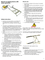
After placing the device in a desired place and
blocking the wheels:
- plug in the device.
- check the level of water in the closed circuit tank
- check if the safety switch on the controller housing
is not depressed (by gently turning it as arrows on the top
of the switch) Fig3 no.4
- set the main switch to position "1" Fig 1
Power supply unit with the main switch.
230V socket Main switch
Fig.1
After the above steps, the driver panel will start.
Fig.2
400V or 230V power supply.
Check the feeder chain work direction before starting
Fig.3
1) Controller unit
2) Chain speed adjustment
4) Safety switch
3) Changing the working direction of the feeder chain
5) Knife angle adjustment
The controller unit buttons (Fig. 2) are used to switch the
machine on and off and to configure the parameters.
The settings are stored in the controller memory.

2.1. Buttons:
Button 1 – „START” Switching on the extruder - counter
clockwise
After entering the menu (button no. 4)
configure the extruder rotation
(increase of rotation speed)
Settings range from 10%-100%.
Button 2 – „START” Switching on the extruder - clockwise
After entering the menu (button no. 4)
configure the extruder rotation
(decrease of rotation speed)
Settings range from 10%-100%.
Button 3 – „STOP” Stopping the extruder
Button 4 – […] Menu Menu entering/exiting button […]
Fig 5.
After entering the menu, we can start
programming, i.e. change the speed
and temperature.
Button 5 – „START” Activation of the uncapping knives
Button 6 – „STOP” Dectivation of the uncapping knives
Button 7 – „START”
Button value change
„PLUS”
Switching on the heating of knives.
After entering the menu (button no.4)
set the temperature of the knives S-
increasing the temperature.
Setting range from 30°C - 95°C
T - current knife temperature
Button 8 – „STOP”
Buttonvalue change
„MINUS”
Switching on the heating of knives.
After entering the menu (button no.4)
set the temperature of the knives S-
decreasing the temperature.
Setting range from 30°C - 95°C
T - current knife temperature
Button no 4 […] Fig.5 entering i Fot.6 exiting menu
2.2. Controller operation
Fig.4.
View of the controller panel before entering the menu.
Below is a view of the controller panel after entering the
menu.
Fig.5.
After entering the controller menu (button no. 4) we can set
parameters such as speed and temperature.
The menu button [...] is active in the STOP state as well as
in the START state, which enables changing parameter
values before and during the device operation.
Fig.6.
The changing of the speed of the screw in the extruder is
performed by means of buttons no.1 "PLUS" increasing the
value of the parameter or no.2 "MINUS" decreasing the
value of the parameter.
Fig.7.
Setting the temperature of the knives parameter S.
The temperature is set using buttons no. 7. "PLUS" to
increase the value of the parameter and no.8. "MINUS" to
decrease the value of the parameter.
Press again the button no. 4 [...] to exit the menu.

Activation of individual machine components is indicated by
moving graphics on the display.
Fig.8.
Switching on the heating of knives - button no. 7
The set temperature is maintained by the controller.
Fig.9.
Switching off heating of knives - button no. 8
When the knives have reached the pre-set temperature the
machine is ready for uncapping process.
Then turn on the uncapping knives
Fig.10.
Włączenie noży odsklepiających - przycisk nr.5
Fig.11.
Stopping the knives - button no. 6
Fig.12. Activation of extruder operation
Fig.13.
Stopping the extruder
Fig.14.
Reversing the extruder

STATUS top).
(E.2) PB2
STATUS
Fault / depressed button 2 (left side).
(E.3) PB3
STATUS
Fault / push button 3 (left side).
(E.4) PB4
STATUS
Fault / depressed button no. 4 (left side,
bottom).
(E.5) PB5
STATUS
Fault / depressed button no. 5 (right
side, top).
(E.6) PB6
STATUS
Fault / depressed button no. 6 (right
side).
(E.7) PB7
STATUS
Fault / depressed button no. 7 (right
side).
(E.8) PB8
STATUS
Fault / depressed button 8 (right side,
bottom).
(E.9) T1
SENSOR
Fault or malfunction of temperature
sensor T1.
(E.10) T > Tmax Temperature measured by sensor T1
too high.
(E.11) T < Tmin Temperature measured by sensor T1
too low.
(E.12) ALARM
ST1
Alarm notification from input D4.
(E.13) ALARM
ST2
Alarm notification from entrance D5.
3 Instructions for use
Elements
Fig.15.
Elements:
3.1 Controller
3.2 Frame
3.3 PSU box
3.4 Power cord 400V lub 230V
3.5 Leveling feet
3.6 Frame slides
3.7 Uncapping knives
3.8 Discs piercing uncapped cells in the frame (in
Fig. 17 close-up view)
3.1. General rules – preparation for use
Before starting uncapping, adjust the sliders "6" Fig.15.
with the screws shown in Fig.16.
Fig.16.
The adjustment of the frame sliders is carried out
according to the height of the uncapped frames and the
width of the top bars.
To do this, place a few suitable frames on the feeder and
adjust the top and bottom sliders accordingly.
The next step is to adjust the knife spacing according to
the comb thickness.
This will ensure optimum uncapping conditions.
Fig.17.
ERROR DESCRIPTION
(E.0) CPU
STATUS
Internal controller fault
(E.1) PB1 Fault / depressed button 1 (left side,
2.3. Error codes
The PC-03 controller is equipped with
advanced error detection mechanisms. The detection of
any error activates the emergency stop action and calls
up the error report screen. The error report screen
is displayed continuously. It is therefore necessary to switch
off the power supply, remove the source of error and
switch on the controller again.

Knife spacing is adjusted by two levers, adjustment lever A
and locking lever B Fig.18.
Fig.18.
3.2. Heating system
WARNING!!!!
The tank should be filled up with liquid after the unit
has been disconnected from the mains via the filler Fig.
B!
The closed circuit is topped up before start-up with a
quantity of (6 LITRES) in proportion:
5 L. WATER + 1 L. propylene glycol (organic
compound)
IMPORTANT!!!
During operation the level of liquid in the closed circuit must
be checked regularly. If the liquid level falls to the minimum
(see level indicator Fig. A), stop the unit, disconnect it from
the power supply and refill the tank.
After topping up the liquid, switch on the heating of the
knives again. Wait for the reheating of the uncapping
knives. Start the uncapping machine and return to the
uncapping process.
A Liquid level indicator in closed circuit
B Filler port through which we refill the liquid tank.
3.3. Uncapping
Start heating the knives with the "START" button Fig. 8.
When the knives have heated up, place the frames in the
previously adjusted sliders "6" Fig. 15, start the uncapping
machine with the "START" button Fig. 10 and start the
uncapping process. If the uncapping machine is also
equipped with an extruder, start it with the "START" button
Fig. 12.
Check the quality of the uncapped frames and make
adjustments if necessary.
Before adjusting, stop the operation of the uncapping
machine and the heating of the knives ("STOP" button
Fig. 11 and Fig. 9)! Then switch off the power at the control
box "3" Fig.15.
A
B

Only in this switch position can the necessary
adjustments to the machine set-up be made.
WARNING!
In case of necessity of immediate stopping of the device
press the emergency "STOP" button "4" Fig. 3 on the
controller box "1" Fig 3.
Pressing the emergency button switches off the heating
system, circulation pump, uncapping knives and power
supply of the circulation tank heater.
4 Technical specifications
-construction, stainless steel
-uncapping capacity 5-8 frames/min. depending on type of
frames
-knife drive,0.18kW
-frame feeder 0.12kW
-knives heated by liquid in closed circuit 2 kW
-maximum temperature of knives 95°C
-Power supply 230V or 400V
5 Cleaning and maintenance
IMPORTANT!
Unplug the device from the power supply outlet
and wait until all elements of the device have
cooled down before performing any maintenance
or cleaning!
Clean the uncapping table and uncapping knives thoroughly
before first use.
Wash the machine with hot water and a small amount of
detergent approved for washing equipment intended for food
contact, using a soft flannel cloth, making sure to protect the
electrical components.
After washing, rinse thoroughly with clean water.
The chain carrying the frames should be dried after washing
and do not use any preservatives!
The uncapping machine is ready for use.
After the uncapping process is complete, wash, dry the
machine and and store in a dry room.
6 Waste disposal and environmental
protection
The used product must be disposed in accordance with the
local regulations. Return the device to a collection point from
where it can be submitted for environmentally compatible
recycling.
The consumer has the right to return used equipment
directly to the manufacturer's distribution network, free of
charge, while replacing it with a new unit as long as the used
device is of the same kind and same application as the
newly purchased device.
7 Warranty
The product purchased from the Lyson Company is covered
by a manufacturer's warranty. The warranty period is 24
months from the date of purchase.
All purchased products come with receipts or VAT invoices.
Warranty details at:
www.lyson.com.pl
Do not make any adjustments while the uncapping
machine is switched on. Be careful with hot
uncapping knives.
The correct switch position during adjustment is "0"!!!
Fig.19. Switch on the control box "0" position
/