
1
finger on top of the sensor.
You hear three short beeps
Ardwolf A10 Fingerprint Touchscreen Door Lock
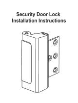
Installation Instructions
Ardwolf A10 FINGERPRINT KEYPAD LOCK INSTALLATION
INSTRUCTIONS
Tools needed for new installation:
Pencil, Chisel, Tape Measure, Hammer, Phillips Screwdriver, 1” (25 mm) & ⅛” (3
mm) Drill Bits, 2 ⅛” (54 mm) Hole Boring Bit, Power Drill.
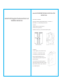
1. Mark door.
1.1 Mark centerline on door and jamb (see fig. 1).
1.2 Stand so door swings towards you.
2. Drill holes on door (see fig. 2, and 3), dimension 8 mm hole is optional.
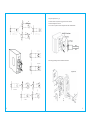
3. Install Latch.
3.1 Latch is adjustable, you may set the latch to either
2 ⅜” (60 mm) or 2 ¾” (70 mm) backset (see fig.4).
3.2 Use faceplate as a pattern for mortise and pilot
holes. The faceplate should fit flush (see fig. 5).
3.3 Install as shown for appropriate latch type. Ensure
bevel faces doorjamb.
3.4 Check square hole edge on the latch spindle. The
square hole edges MUST are either parallel or vertically
aligned with latch centerline (see fig. 6), otherwise refer
fig. 7 to adjust latch spindle.

2 3
4. Prepare doorjamb (see fig. 8).
4.1 Mark centerlines on jamb exactly opposite center of latch hole.
4.2 Make rectangle holes as shown.
4.3 Use strike as a pattern for mortise and pilot holes. Strike should fit flush.
Part II. Fingerprint Keypad Lock Installation Instructions

4 5
fig. 1
fig. 2
fig. 3
fig. 4
fig. 5
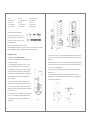
(A) Key
(B) Outside Lever
(C) Cylinder
(D) Outside chassis
(E) Lever Catch
(F) Latch
(G) Latch/Strike Screws
(H) Strike
(I) Inside chassis
(J) Allen Screw
(A) Mounting Screws
(B) Inside Lever
(M) Cover
(N) Cover Screw
(O) Allen Wrench
The lock comes with two (K) Mounting
Screws M5x60 2⅜” (60 mm) long, one (N)
M3x25 1”(25 mm) long Cover Screw, one (J)
Allen Screw, one (E) Lever Catch and 4 pieces
(G) Latch/Strike Screws.
Note: The lock fit door thickness between 1⅜” and 2⅜”.
Contact manufacturer to order M5x50 2” (50 mm) long screw if your door thickness is less than 1⅜”.
Tools needed: Phillips Screwdriver, Tape Measure, Pencil, and Flathead Screwdriver.
IMPORTANT NOTES:
• DO NOT use a power drill for installation!
• Install and test lock with door open to avoid being locked out.
1. Install lock on the door.
1.1 The dent should be on 12-clock position (see fig. 1), if not,
rotate Square Spindle to let the dent be on 12-clock position.
1.2 Install the outside chassis unit (see fig. 2). Slide wire through
hole on door. Slide square spindle and poles smoothly through
holes in latch. Take care to keep outside chassis vertically aligned
during installation. Check latch setting and door dimensions if
there is any problem.
1.3 Take care to keep inside chassis vertically aligned during
installation. Connect wire and arrange wire in empty space, take
care to ensure wire is not pinched or crushed at any point during
installation. The Square Spindle slide smoothly into square hole on
Lever Spindle (see fig. 3).
1.4 Insert Mounting Screws to mounting hole on the inside chassis
(see fig. 4), screws should slide smoothly through hole on door.
Use Philip Driver to drive two screws into mounting hole on
mounting poles.
2. Set up inside Lever: Put Lever on Lever Spindle then use Allen Wrench to put Allen Screw
(see fig. 5). Use Allen Wrench to take Allen Screw off then pull out Lever when you want to
remove Lever.
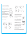
3. Set up outside Lever: You may set up lever to fit for either left-handed or right-handed door.
3.1 Make sure that the dent is on 12-clock position when lock hasn’t be installed on the door
(see fig. 1), if not, rotate Square Spindle.
3.2 Rotate inner Spindle by Flathead Screwdriver let Cylindrical Protrusions horizontally
aligned (seefig. 6).
3.3 Insert Lever Catch in the right side hole on Lever Spindle completely if your door is
left-handed (see fig. 7a), otherwise put it in the left side hole (see fig. 8a). The big end on the
Lever Catch goes into the hole first.

6 7
fig.
7
fig.
8
fig.
9
fig.
10
3.4 Insert Cylinder in Lever Spindle. The Cylinder’s tail
toward left if you want to set lock as left-handed (see fig.
7b), otherwise the Cylinder’s tail toward right (see fig. 8b).
3.5 Put lever on Lever Spindle (see fig. 7c, 8c). The lever
will stop at half way when you push Lever in. Insert key
into Cylinder, push the lever (see fig. 9b) and rotate the key
CLOCKWISE until the lever is pushed in. Key should be
rotated around 90° but could be up to 135° (see fig. 9a).
Rotate the key counter CLOCKWISE (see fig. 9c) then take
the key out (see fig. 9d).
3.6 Remove Lever (if necessary): Insert key into Cylinder
then rotate key CLOCKWISE 90°, use Allen Wrench or
paper clip to push Lever Catch in then pull lever out (see
fig.10). Rotate key COUNTER CLOCKWISE 90° then
take key out. Use Flathead Screwdriver to rotate
Cylindrical Protrusions, the Lever Catch will protrude.
Take the Lever Catch out, keep it in safe place.
3.7 Switching Levers (if necessary): Levers can be reversed
to extend toward hinges. Refer 3.6 to remove lever then
following 3.1 to 3.5 to set up lever.
4. Install 4 brand new
AA Alkaline batteries (NOT
included, do
not use rechargeable batteries). Alkaline Batteries Warning: Do
not install backwards, charge, put in fire, or mix with other
battery types, may explode or leak causing injury. Replace all
batteries at the same time.
5. Slide cover down then tight cover screw (see figure 1
1).
6.
T
esting lock: Rear lever should be pushed down and lifted
up. The lock may keep unlock after installation. Enter default
code 1234 then press #. The lock will lock by itself after 5
second, otherwise check latch if it is broken.
7. Caution: User MUST install strike plate included in package.
The existing strike must be removed if there is one on
doorjamb. Check the operation of the latch by ensuring that the
latch plunger stops against the strike plate and does not slide
into the strike opening when the door is closed (see fig. 12). If
that situation occurs, then a total lockout may occur
.
This
situation will void our warranty of the complete lock
mechanism. If necessary
, correct the door over
-travel by using
the rubber bumper (see fig. 13).
Y
ou may buy the rubber
bumpers from your local hardware store.
8. Lock removal: Reverse step 5, 4 and 2. Refer step 3.6 to remove outside Lever.
Reverse step 1.4 and 1.3 to remove outside chassis and inside chassis from the door
.

8
I
nstallation Optio
n:
Product return:
Please refer installation instruction to remove lock from door, remove levers
from lock, and then refer the following diagram to pack lock.
fig. 12
fig. 13
The lock will stay on vertical position on the door as long as
the two mounting screws were tied up in most case. You may
put a tapping screw on inside chassis to increase lock stability.
1. Remove two screws in battery compartment. You will see
mounting hole under battery compartment.
2. Use 3/8" (8 mm) Drill Bits to drill a hole on door through
mounting hole.
3. Put screw pole on front metal plate.
4.
Put screw through mounting hole to connect with screw
pole.
5. Put battery compartment back.
-
 1
1
-
 2
2
-
 3
3
-
 4
4
-
 5
5


Ask a question and I''ll find the answer in the document
Finding information in a document is now easier with AI
Related papers


Other documents
-
IDEAL Security SKVKBL Installation guide
-
Johnson Hardware 15213PK1 Installation guide
-
-
Ingersoll-Rand FE595 User manual
-
Schlage Control Smart Deadbolt FE410F Installation guide
-
-
 EverPlus home security door lock Installation guide
-
Dormakaba RT Series Installation guide
-
Alarm Lock Trilogy Networx Double-Sided PDL6300 Installation Instructions Manual
-
