Page is loading ...

KVH I ndust r i e s, I nc .
A Gui de t o Tr a cVi si on
®
Cr ui se r
• Technical Manual
• User’s Guide
• Installation Guidelines

Congratulations!
You have selected one of the most advanced marine satellite
tracking systems available today. KVH
®
Industries’ TracVision
®
Cruiser is designed for use with DIRECTV
®
and the DISH
™
Network on vessels that typically experience low to moderate
motion. This manual provides detailed instructions on the
proper installation, use, and maintenance of your TracVision
Cruiser system.
Throughout this manual, important information is marked for
your attention by these icons:
Direct questions, comments, or suggestions to:
KVH Industries, Inc.
50 Enterprise Center
Middletown, RI 02842 USA
tel: +1 401 847-3327
fax: +1 401 849-0045
e-mail: [email protected]
internet: http://www.kvh.com
A helpful tip that either directs you to
a related area within the manual or
offers suggestions on getting the
highest quality out of your system.
An alert to important information
regarding procedures, product
specifications, or product use.
An electrical safety warning to help
identify electrical issues that can be a
hazard to either this KVH product or
a user.
Information about installation,
maintenance, troubleshooting, or
other mechanical issues.
TracVision Cruiser
Serial Number
This serial number will be required
for all troubleshooting or service
calls made regarding this product.
KVH Part # 54-0144 Rev. C
© 1999, KVH Industries, Inc.

TracVision
®
and KVH
®
are registered trademarks of
KVH Industries, Inc.
DIRECTV
®
is an official trademark of DIRECTV,
a unit of GM Hughes Electronics Corporation.
DISH
™
Network is an official trademark of
EchoStar Communications Corporation.

Table of Contents
1Introduction . . . . . . . . . . . . . . . . . . . . . . . . . . . . . . .1-1
1.1 Digital Satellite Television . . . . . . . . . . . . . . . . . . . . . . . . . . . . . .1-1
1.2 TracVision Cruiser System Overview . . . . . . . . . . . . . . . . . . . . .1-1
1.2.1 TracVision Cruiser Components.............................................1-2
1.2.2 Integrated Receiver Decoder..................................................1-2
1.3 Materials Provided with TracVision Cruiser . . . . . . . . . . . . . . . .1-3
1.3.1 Additional Materials Required for
TracVision Cruiser Use...........................................................1-3
2Installation . . . . . . . . . . . . . . . . . . . . . . . . . . . . . . . .2-1
2.1 Overview of Installation . . . . . . . . . . . . . . . . . . . . . . . . . . . . . . .2-1
2.1.1 Installation Tools and Materials Required...............................2-1
2.1.2 Kitpack....................................................................................2-2
2.2 Choosing the Best Location and Getting
the Best Reception . . . . . . . . . . . . . . . . . . . . . . . . . . . . . . . . . . .2-2
2.3 Mounting the Antenna Unit . . . . . . . . . . . . . . . . . . . . . . . . . . . . .2-3
2.4 Connecting the Antenna Unit . . . . . . . . . . . . . . . . . . . . . . . . . . .2-6
2.4.1 Connecting the Antenna Data Cable to the IRD ....................2-8
2.4.2 Connecting the Antenna to Vessel Power ............................2-10
2.4.3 Connecting the Antenna RF Signal Cable to the IRD ..........2-11
2.5 Connecting the IRD to Vessel Power . . . . . . . . . . . . . . . . . . . .2-14
2.6 Checking Out the System . . . . . . . . . . . . . . . . . . . . . . . . . . . . .2-15
2.7 Completing the Installation Process . . . . . . . . . . . . . . . . . . . .2-16
3Operation . . . . . . . . . . . . . . . . . . . . . . . . . . . . . . . . .3-1
4Troubleshooting . . . . . . . . . . . . . . . . . . . . . . . . . . . . .4-1
4.1 Causes and Remedies for Common Operational Issues . . . . . .4-1
4.1.1 Satellite Signal Blocked..........................................................4-2
4.1.2 Outside Satellite Coverage Zone ...........................................4-2
4.1.3 Radar Interference..................................................................4-2
i
54-0144 Rev. C

4.1.4 Vessel Turning During Startup................................................4-2
4.1.5 Incorrect or Loose RF Connectors .........................................4-3
4.1.6 Passive Multiswitch Used.......................................................4-3
4.2 IRD Troubleshooting . . . . . . . . . . . . . . . . . . . . . . . . . . . . . . . . . .4-3
4.2.1 EchoStar IRD Commissioning ................................................4-3
4.2.2 IRD Data Port or Cable/Wiring ...............................................4-3
4.2.3 IRD Faulty...............................................................................4-3
4.2.4 Failed IRD Status Check ........................................................4-4
4.3 Antenna Gyro and LNB Faults . . . . . . . . . . . . . . . . . . . . . . . . . .4-5
4.4 Computer Diagnostics . . . . . . . . . . . . . . . . . . . . . . . . . . . . . . . .4-5
4.5 Maintenance Port Parser Commands . . . . . . . . . . . . . . . . . . . . .4-5
5Maintenance . . . . . . . . . . . . . . . . . . . . . . . . . . . . . . .5-1
5.1 Warranty/Service Information . . . . . . . . . . . . . . . . . . . . . . . . . . .5-1
5.2 Preventive Maintenance . . . . . . . . . . . . . . . . . . . . . . . . . . . . . . .5-1
5.3 Replaceable Parts . . . . . . . . . . . . . . . . . . . . . . . . . . . . . . . . . . . .5-2
5.4 Field Replaceable Unit Procedures . . . . . . . . . . . . . . . . . . . . . .5-3
5.4.1 PCB Removal and Replacement............................................5-5
5.4.2 RF Detector ............................................................................5-6
5.4.3 Antenna Gyro Assembly.........................................................5-6
5.4.4 Antenna LNB Replacement....................................................5-8
5.4.5 EchoStar Adapter Replacement .............................................5-9
5.5 Preparation for Shipment . . . . . . . . . . . . . . . . . . . . . . . . . . . . .5-10
Appendix A System Specifications . . . . . . . . . . . . . . . . . .A-1
Appendix B Functional Block Diagram . . . . . . . . . . . . . . . .B-1
Appendix C Data Cable Wiring . . . . . . . . . . . . . . . . . . . . .C-1
C.1 Wiring TracVision Cruiser to a 15-pin Data Connector . . . . . . .C-1
C.2 DB9 Data Connector Pin Assignments . . . . . . . . . . . . . . . . . . .C-2
Appendix D EchoStar IRD Commissioning Procedure . . . . . .D-1
ii

Appendix E Startup Data Sequence . . . . . . . . . . . . . . . . . .E-1
Appendix F Maintenance Port Parser Commands . . . . . . . . .F-1
F.1 System Co mmands . . . . . . . . . . . . . . . . . . . . . . . . . . . . . . . . . . .F-1
F.2 Manual Positioning Comma nds . . . . . . . . . . . . . . . . . . . . . . . . .F-2
F.3 Operational Comm ands . . . . . . . . . . . . . . . . . . . . . . . . . . . . . . .F -3
F.4 Tr acking a nd Conscan Commands . . . . . . . . . . . . . . . . . . . . . .F-4
List of Figures
Figure 1-1 TracVision Cruiser Identifies and Compensates
for Vessel Motion . . . . . . . . . . . . . . . . . . . . . . . . . . . . . . .1-1
Figure 1-2 TracVision Cruiser Single IRD System Configuration . . . .1-1
Figure 1-3 Primary Components of TracVision Cruiser . . . . . . . . . . . .1-2
Figure 2-1 Forward Shipping Restraint and LNB Arm
(Arranged for Shipping) . . . . . . . . . . . . . . . . . . . . . . . . . .2-3
Figure 2-2 TracVision Cruiser Shipping Restraints (Top View) . . . . . .2-3
Figure 2-3 Stiffening Plate Dimensions . . . . . . . . . . . . . . . . . . . . . . .2-4
Figure 2-4 Orientation of the Antenna Unit and Stiffening Plate . . . . .2-4
Figure 2-5 Recommended Drain Hole Locations . . . . . . . . . . . . . . . .2-5
Figure 2-6 Shipping Restraint (Arranged for Storage) . . . . . . . . . . . .2-5
Figure 2-7 Bolting TracVision Cruiser to the Deck (Side View) . . . . . .2-6
Figure 2-8 Proper Wire-to-Terminal Connection . . . . . . . . . . . . . . . . .2-6
Figure 2-9 Moving the Antenna Reflector . . . . . . . . . . . . . . . . . . . . . .2-7
Figure 2-10 Cable Port Assignments (Exterior of Baseplate) . . . . . . . .2-7
Figure 2-11 Cable Overlap within the TracVision
Cruiser Baseplate . . . . . . . . . . . . . . . . . . . . . . . . . . . . . . .2-7
Figure 2-12 Proper Terminal Strip Wiring Arrangement –
Data Cable . . . . . . . . . . . . . . . . . . . . . . . . . . . . . . . . . . . .2-8
Figure 2-13 Examples of DIRECTV IRD Connectors . . . . . . . . . . . . . .2-8
Figure 2-14 EchoStar Adapter Installation . . . . . . . . . . . . . . . . . . . . . .2-9
Figure 2-15 Proper Wire-to-Terminal Connection . . . . . . . . . . . . . . . .2-10
Figure 2-16 Proper Terminal Strip Wiring Arrangement –
Power Cable . . . . . . . . . . . . . . . . . . . . . . . . . . . . . . . . .2-10
iii
54-0144 Rev. C

Figure 2-17 Wiring TracVision Cruiser to Vessel Power . . . . . . . . . . .2-11
Figure 2-18 Connecting the RF Cable to TracVision Cruiser . . . . . . . .2-11
Figure 2-19a-d Attaching the Provided F-connector to an RF Cable . . . .2-12
Figure 2-20 Connecting TracVision Cruiser to Multiple IRDs . . . . . . .2-13
Figure 2-21 Connecting to Multiple Multiswitches . . . . . . . . . . . . . . . .2-14
Figure 5-1 Antenna, PCB, and Rotating Plate . . . . . . . . . . . . . . . . . .5-3
Figure 5-2 Close-up of Linear Actuator, Pivot Bracket, and Pin . . . . .5-3
Figure 5-3 Antenna Assembly . . . . . . . . . . . . . . . . . . . . . . . . . . . . . .5-4
Figure 5-4 Close-up of RF Detector, PCB, and Cover . . . . . . . . . . . .5-4
Figure 5-5 PCB Connector Locations – Rear View (not to scale) . . . .5-5
Figure 5-6 Attaching the Shipping Restraints to
the Antenna Baseplate . . . . . . . . . . . . . . . . . . . . . . . . . .5-10
Figure 5-7 Securing the Forward Shipping Restraint . . . . . . . . . . . .5-10
Figure C-1 DB9 Male and Female Connector Arrangement . . . . . . . .C-2
List of Tables
Tab l e 1-1 TracVi s ion Cruis er P a ckin g Li st . . . . . . . . . . . . . . . . . . . 1 -3
Tab l e 2-1 Ki t pack Cont ents . . . . . . . . . . . . . . . . . . . . . . . . . . . . . .2-2
Tab l e 2-2 TracVi s ion Cruis er O p erat i ona l Mes s ages . . . . . . . . . . 2 -15
Tab l e 2-3 DS S On- S cree n Messa g es . . . . . . . . . . . . . . . . . . . . . 2 -16
Tab l e 3-1 TracVi s ion Cruis er A u toma ted Proce d ure s . . . . . . . . . . . 3 -2
Tab l e 4-1 Troub l esh o otin g Ma tri x . . . . . . . . . . . . . . . . . . . . . . . . .4 -1
Tab l e 5-1 Fi e ld R e pla c eabl e Units . . . . . . . . . . . . . . . . . . . . . . . .5- 2
Tab l e A- 1 TracVi s ion Cruis er S y stem Spec i fic a tion s . . . . . . . . . . .A- 1
Tab l e C-1 Al t erna te W i ring Arr a nge m ent for Tr acVi s ion Cruis e r
Data Cable to DB15 (15-wire) Connector . . . . . . . . . . .C-1
Tab l e C-2 DB 9 Pin Func t ion s and Colo r Cod e . . . . . . . . . . . . . . .C- 2
Tab l e F-1 Sy stem Comm ands . . . . . . . . . . . . . . . . . . . . . . . . . . . .F-1
Tab l e F-2 Ma nual Posi tion i ng Co mma n ds . . . . . . . . . . . . . . . . . . .F-2
Tab l e F-3 Op erat iona l Com m and s . . . . . . . . . . . . . . . . . . . . . . . .F- 3
Tab l e F-4 Trac k ing and Co nsc a n Comma n ds . . . . . . . . . . . . . . . .F- 4
iv

Low-speed
Data Port
TV
11-16 Volts DC
2.5-3.5 Amps
Antenna Unit
9-Pin PC
Communications
Port
IRD
Figure 1-2
Tra cVi sio n Cr uis er S in gle IRD
System Configuration
1Introduction
1.1 Digital Satellite Television
The DIRECTV
®
and DISH
™
Network systems transmit digital
audio and video data from land-based transmitters to a
satellite “parked” above the equator. Each satellite relays the
signals in spot beams covering the continental United States
and contiguous waters. TracVision Cruiser is designed to
identify, lock on to, and track the appropriate satellite, both
while your vessel is at rest and in motion.
1.2 TracVision Cruiser
System Overview
Your KVH TracVision Cruiser employs a state-of-the-art
actively stabilized antenna system designed for use with
Ku Band satellite television reception. This vessel-referenced
stabilization system is enhanced by a conical scan tracking
function to detect and lock on to the strongest signal, resulting
in the clearest reception possible.
Acomplete satellite TV system includes the TracVision Cruiser
connected to an Integrated Receiver Decoder (IRD), aka a
“satellite receiver,” and a television set. A desktop or laptop
computer is used to conduct diagnostics. The interrelationship
of units is illustrated in Figure 1-2. System specifications and a
functional block diagram are provided in Appendices A and B,
respectively.
1-1
Introduction
54-0144 Rev. C
TracVision
Figure 1-1
Tra cVi sio n Cr uis er I de nti fie s an d
Compensates for Vessel Motion

1.2.1 TracVision Cruiser Components
The Antenna Unit includes the antenna positioning
mechanism, signal front end, power supply and control
elements. These include antenna drive controls and
mechanisms, the cable wrap subassembly, antenna gyro
sensor, power conditioning and regulating circuits, and the RF
detector. The antenna is a parabolic dish mounting a dual port
low noise block (LNB) converter with built-in preamplifier. A
molded ABS radome encloses the baseplate and is secured in
place with standard fasteners. Liquid-tight (watertight) fittings
located on the back of the baseplate join the power, signal, and
control cabling to below-decks units.
1.2.2 Integrated Receiver Decoder
The IRD receives satellite signals from the Antenna Unit for
signal decoding, processing and channel selection, and sends
the signals to the TV set for viewing. Messages are sent from
the IRD to the Antenna Unit and messages are received from
the Antenna Unit for display on the television screen. The IRD
also provides the interface for the user to activate authorization
for reception. Please refer to the User’s Manual provided with
your selected IRD for complete operating instructions.
Multiple IRDs may be connected to the Antenna Unit to
provide satellite signals to a number of TV sets. When two
or more IRDs are connected to the same antenna, an active
multiswitch must be installed between the Antenna Unit and
1-2
AGuide to TracVision Cruiser
Radome
Antenna Unit/
Baseplate
Antenna
Reflector
LNB
Gyro
Figure 1-3
Primary Components of
Tra cVi sio n Cr uis er
On-screen messages are not
available with a DISH Network IRD.
For directions on installing a
multiswitch with your TracVision
Cruiser system, refer to Section
2.4.3, “Connecting the Antenna RF
Signal Cable to the IRD.”
Always lift the antenna unit by the
gray baseplate and not the radome,
antenna reflector, or internal
mechanical assemblies.
NEVER pick up the unit by the LNB
or the gyro!

the IRDs. The multiswitch contains relays that select the proper
output from the antenna LNB to send to the IRD. In multiple
IRD installations, all IRDs must be for the same satellite
television service (i.e., DIRECTV or DISH Network).
1.3 Materials Provided with
TracVision Cruiser
Table 1-1 lists the units, cables, and materials packed in the
TracVision Cruiser package by name and KVH part number.
Component KVH Part No.
Antenna Unit (comprising): 01-0225
Baseplate Assembly 02-0952
Radome Assembly 02-0953
Stiffening Plate 20-0684
RF Cable 32-0589-60
Power Cable 32-0590-60
Data Cable 32-0591-60
Kitpack* 72-0094
Installation and Operation Manual 54-0144
* A complete listing of kitpack contents is provided in Section 2.1.2, “Kitpack.”
1.3.1 Additional Materials Required for
TracVision Cruiser Use
To make full use of your new TracVision Cruiser and receive
satellite TV on the water, you will need to provide/purchase
the following:
•
Television
• Appropriate IRD for your selected satellite
TV service (if using the DISH Network, a
Series 4000 or 5000 IRD will be required)
• Sealing materials to weatherproof cable holes
and seal mounting plate
• Optional KVH EchoStar Adapter (for use with
the DISH Network service and IRD)
1-3
Introduction
54-0144 Rev. C
Operation of the DISH Network
requires the purchase of an
EchoStar IRD Adapter. The
adapter is not shipped in the main
TracVision Cruiser container. To
purchase an EchoStar Adapter,
contact KVH or your local KVH
dealer and ask for KVH Product
Number 02-0899.
Table 1-1
Tra cVi sio n Cr uis er
Packing List
Cables for the TracVision Cruiser
are stored beneath the antenna unit
during shipping.


2-1
Installation
54-0144 Rev. C
2Installation
2.1 Overview of Installation
TracVision Cruiser is designed for simple installation and
setup. Just follow these easy steps:
1. Choose the antenna location.
2. Mount the antenna unit.
3. Connect the antenna unit cables.
4. Connect the antenna unit to the TV IRD.
5. Connect the TV IRD to the TV.
2.1.1 Installation Tools and Materials Required
• Electric drill, assorted drill bits and
1
⁄2˝ hole saw
• Socket wrenches
• Phillips and flat tip screwdrivers
•Installation kitpack containing stainless steel
hardware for mounting the Antenna Unit,
power switch, and switch plate
• Augat Snap ‘n Seal Crimp/Strip Tool (Part
Number IT1000) if using the KVH-provided
F-connector
• Silicone sealant or RTV
•
Wire strippers
• Terminal crimp tool
•Optional PC with terminal emulation software
such as PROCOMM, Windows Terminal, or
Windows 95 Hyperterminal. Use of a PC during
all installations is highly recommended.
Plan the entire installation before
proceeding! Take into account
component placement, running
cable distances between units, and
accessibility to the equipment after
installation.
While some DIRECTV IRDs offer
on-screen messages, it is
recommended that a PC be
available for all TracVision Cruiser
installations.
WHEN INSTALLING TRACVISION
CRUISER, DO NOT BEND OR
FLEX THE BASEPLATE TO
CONFORM WITH THE DECK
SURFACE!

2-2
AGuide to TracVision Cruiser
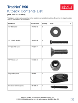
2.1.2 Kitpack
Table 2-1 lists the materials provided in the TracVision Cruiser
kitpack.
Part Qty. KVH Part No.
Rocker switch 1 12-0048
Switch plate 1 19-0167
RF F-connector 2 23-0170
Term i n al cr imp (fema l e) 5 23- 0 1 88- 0 3
Tie-wrap 5 22-0013
1
⁄4-20 x 3˝ Hex head Cap Screw 6 14-0250-48
(stainless steel)
1
⁄4 Flat washer (stainless steel) 6 14-0251
2.2 Choosing the Best Location and
Getting the Best Reception
• The ideal antenna site has a clear view of the
horizon/satellite all around.
• The closer the antenna reference is aligned with
the vessel’s centerline, the smaller the pool of
tracking errors will be.
• Place the Antenna as close as possible to the
intersection of the vessel’s fore-and-aft centerline
and midships.
• The Antenna Unit should not be too high off the
water (a height above the waterline no more than
half the vessel length).
• Keep the antenna out of line with nearby radars,
as their energy levels may overload the antenna
front-end circuits. If necessary, position the
Antenna Unit so it is at least four feet (1.3 meters)
above or below the level of the radar.
• Make sure that the mounting surface is rigid so
that it cannot flex when the vessel vibrates. If
necessary, add a strength member to the mounting
site to stiffen it.
Table 2-1
Kitpack Contents
Always lift the antenna unit by the
gray baseplate and not the radome,
antenna reflector, or internal
mechanical assemblies, pictured
previously in Figure 1-3.
NEVER pick up the unit by the LNB
or the gyro!
The radome exterior is treated with
a special finish selected for
ultraviolet stabilization and
transparency to satellite signals. Do
not apply additional paints or
finishes. Application of any other
coatings voids the warranty.

2-3
Installation
54-0144 Rev. C
2.3 Mounting the Antenna Unit
KVH recommends that TracVision Cruiser be mounted with
the cable ports facing aft. However, the unit can be installed in
whatever orientation is most convenient for the vessel and the
mounting area. Mount the TracVision Cruiser with the
supplied stiffening plate using the following procedure.
1. Remove the eight pan head screws and flat
washers holding the radome onto the baseplate.
Carefully lift the radome straight up until it is
clear of the antenna assembly and set it aside.
Save the screws and flat washers for reinstalling
the radome later.
2. Cut the tie-wraps holding the LNB to the
forward shipping restraint and rotate the LNB
arm clear of the shipping restraint as shown in
Figure 2-1.
3. Remove the six
1
⁄4
-20 x
3
⁄4
" pan head screws, nuts,
lock washers, and flat washers holding the
antenna unit and shipping restraints onto the
stiffening plate. Set aside the shipping restraints
(illustrated in Figure 2-2). Remove the antenna
unit from the stiffening plate. The shipping
restraints, nuts, lock washers, and flat washers
will be used later to complete the installation.
Figure 2-1
Forward Shipping Restraint and
LNB Arm (Arranged for Shipping)
The aluminum stiffening plate
prevents the fiberglass baseplate
from excessive bending when
installed on a curved surface. Its
use is strongly recommended.
3 tie-wraps used
to secure LNB arm
Forward Shipping Restraint
Forward Shipping Restraint
Nuts and Washers
LNB
The six
1
⁄4-20 x
3
⁄4" pan head screws
are for shipping only, and are not
used as part of the installation
hardware. Retain them for future
shipping needs.
Rotating Plate
Shipping Restraint
Rotating Plate
Shipping Restraint
Forward Shipping
Restraint for
LNB Bracket
Figure 2-2
Tra cVi sio n Cr uis er S hi ppi ng
Restraints (Top View)

2-4
AGuide to TracVision Cruiser
4. Position the stiffening plate in the desired
location on the centerline of the vessel. The
dimensions of the stiffening plate are illustrated
in Figure 2-3.
5. Note that the cables exit the antenna unit at the
wide end of the stiffening plate. The proper
orientation is illustrated in Figure 2-4. While the
stiffening plate is in place, mark location(s) on
the deck to permit convenient cable access to the
liquid-tight fittings on the back of the baseplate.
6. Using the stiffening plate as a template, lay
out the locations of the six mounting holes (also
pictured in Figure 2-4). Drill six
3
⁄8" (10mm)
mounting holes in the installation surface.
Apply a bead of silicone sealant around each
hole.
7. Drill cable access hole(s) in the vessel as needed.
Figure 2-4
Orientation of the Antenna Unit
and Stiffening Plate
26"
21.11"
4.73"
4.0"
19.277"
1.565"
24.0"
1.18"
Figure 2-3
Stiffening Plate Dimensions

2-5
Installation
54-0144 Rev. C
8. There are eight possible drain hole locations in
the baseplate, as illustrated in Figure 2-5. Drill
out ONLY those drain holes that will be facing aft
when the unit is mounted. The drain holes should
be
3
⁄16" and angled as shown in Figure 2-5.
9. Position the stiffening plate over the drilled
mounting holes, and place a bead of silicone
sealant around each of the six mounting holes
on the top surface of the stiffening plate.
10. Place the antenna unit on top of the stiffening
plate, making sure all holes are aligned.
11. The forward shipping restraint can be easily
stored in the baseplate. Place the forward
shipping restraint in reversed position over the
two forward holes (Figure 2-6) and secure it to
the baseplate and the stiffening plate with the
hardware described in Steps 12 and 13.
Figure 2-6
Forward Shipping Restraint
(Arranged for Storage)
Forward Shipping Restraint
Installation Bolts and Washers
LNB
You MUST drill out the drain holes
as indicated to ensure that any
moisture that enters the baseplate
is able to drain. Drill ONLY those
drain holes that will be facing aft
when the antenna is installed.
Recommended
3/16˝ Drain Hole
Positions
Drain Hole Angle
(relative to baseplate)
Figure 2-5
Recommended Drain
Hole Locations
DO NOT store the rotating plate
shipping restraints in the antenna
baseplate as they will interfere with
the rotating plate’s motion.

2-6
AGuide to TracVision Cruiser
12. For each hole, place a
1
⁄4" flat washer on a
3"
1
⁄4-20 bolt (from the kit pack) and place it into
the mounting hole from above.
13. Apply a flat washer, lock washer, and nut (the
ones removed in step 3) to each mounting bolt
from below decks and tighten securely. The
correct mounting arrangement is illustrated in
Figure 2-7.
2.4 Connecting the Antenna Unit
The following sections provide instructions for properly wiring
the Antenna Unit to the IRD and to vessel power.
Tips for Safe and Successful Wiring within
the TracVision Cruiser Baseplate
•
When attaching cables to the TracVision Cruiser
terminal connector strips, make sure the
insulation is stripped back approximately
1
⁄4˝.
Twist the wires gently to help achieve a good
connection. Do not pinch insulation inside the
connector.
• After attaching the power and data cables to the
appropriate terminal connector strips, tug gently
to ensure a firm connection.
Figure 2-8
Proper Wire-to-Terminal
Connection
Insulation
Terminal Connector
1/4˝
Figure 2-7
Bolting TracVision Cruiser
to the Deck (Side View)
Bolt
Flat Washer
Stiffening Plate
Deck
Flat Washer
Hex Nut
Silicone
Lock Washer
Tra cV is i on C ru is er
Baseplate
Silicone

2-7
Installation
54-0144 Rev. C
•
After attaching cables within the TracVision
Cruiser baseplate, eliminate any unnecessary
slack in the cables before tightening the liquid-
tight fittings.
• Run the RF signal cable into the baseplate last. It
will help keep the power and data cables clear
of the antenna and LNB.
• After hooking up all of the wiring and removing
any slack, slowly rotate the antenna reflector
while raising and lowering it to make certain
that the cables are all clear of any moving
elements.
• Check to be certain that the elevation axis
actuator motor shaft (pictured in Section 5,
Maintenance, Figure 5-2) clears all cable
connections.
• Completely seal cable access holes on the deck.
TracVision Cruiser Cable Ports
On one side of the baseplate are four liquid-tight fittings,
which serve the dual purpose of relieving strain on the cables
as well as providing a tight seal around the cable access ports.
When wiring is done properly, the sets of cables will overlap
each other, with the RF cable(s) on top of the power and data
cables as pictured in Figure 2-11. This will help ensure that all
cables stay clear of moving elements within the antenna unit.
Figure 2-10
Cable Port Assignments
(Exterior of Baseplate)
RF1
(#1)
Power
(#4)
RF2
(#2)
Data
(#3)
Figure 2-9
Moving the Antenna Reflector
RF
Data
Power
Figure 2-11
Cable Overlap within the
Tra cVi sio n Cr uis er B as epl ate
DO NOT leave an extra length of
cable within the baseplate as a
service loop. All service loops
should be stored within the vessel’s
cable access.

2-8
AGuide to TracVision Cruiser
2.4.1 Connecting the Antenna Data Cable
to the IRD
TracVision Cruiser will not function properly unless you
connect the data cable, the procedures for which vary based on
your selected satellite TV service. The end of the data cable
fitted with two DB9 connectors remains within the vessel. This
will be hooked up to the IRD as discussed later. For your
reference, DB9 pin assignments and wiring identification
information has been provided in Appendix C. The other end
will be attached to the TracVision Cruiser as described in the
following section.
TracVision Cruiser Data Cable Wiring Process
1. Feed the cable up to the deck and through the
third liquid-tight fitting (#3) from the left as
pictured in Figure 2-10.
2. Refer to Figure 2-12 for the proper arrangement
of data cable wires within the terminal strip.
3. After connecting the data cable to the
TracVision Cruiser, hook up the other end to the
IRD as described in the next subsections.
DIRECTV
The data cable for TracVision Cruiser is equipped with a male
DB9 (low-speed data port) connector. Connect the DB9
connector on the data cable to the low-speed data port on the
back of the IRD. Examples of several common DIRECTV IRDs
are provided to illustrate various locations of the female DB9
port and other IRD connectors.
Figure 2-13
Examples of DIRECTV
IRD Connectors
In from ANT
Out to TV
Video R Audio L
CH3
CH4
S Video
Low-speed Data Port
Satellite In
Early RCA IRD
Out to
TV
CH3
CH4
Low-speed Data Port
Satellite In
In from
ANT
New RCA IRD
IN
CH3
CH4
Low-speed Data Port
Satellite In
OUT
VHF/UHF
VHF(SAT)/UHF
Sony IRD
Shield
Red
Black
Brown/White
Orange/White
White/Orange
Green/White
White/Blue
Blue/White
Shield
Grnd
+12v DC
Grnd
RTN
PC_RXD
PC_TXD
RTN
IRD_RXD
IRD_TXD
Grnd
1
2
3
4
5
6
7
8
9
10
Figure 2-12
Proper Terminal Strip Wiring
Arrangement – Data Cable
All IRDs are susceptible to AC
power fluctuations that can result in
the IRD locking up and requiring a
reset. Refer to Section 4.2, “IRD
Troubleshooting,” for a solution to
this issue.

2-9
Installation
54-0144 Rev. C
Wiring to an IRD with a DB15 Connector
Should the IRD only be equipped with a DB15 connector,
contact KVH for an adapter or follow the alternate wiring
directions provided in Appendix C.
DISH Network
Unlike the DIRECTV IRDs, the EchoStar IRD used with
the DISH Network is not equipped with a DB9 connector.
As a result, you will need to purchase an EchoStar Adapter
(KVH Part Number 02-0899).
The rear of the DISH Network IRD has a port labeled “High
Speed Data Port.”
1. Remove the protective metal plate to expose the
High Speed Data Port. (Save the screws and
plate in the IRD packing material in case the
unit must be returned for repairs.)
2. Install the KVH EchoStar Adapter as shown in
Figure 2-14. Secure the Adapter to the IRD using
the captive screws in the Adapter.
3. Connect the DB9 connector on the data cable to
the EchoStar Adapter DB9.
Commissioning the IRD
Please refer to the user manual that accompanied your IRD for
instructions on properly commissioning the system.
Figure 2-14
EchoStar Adapter Installation
H
ig
h
S
p
e
e
d
D
a
ta
P
o
r
t
ECHOST AR
®
Adapter
This port is static-sensitive, so
observe the proper precautions.
Before starting to install the
adapter, make certain that the IRD
is not plugged into an AC outlet.
/