Page is loading ...

User’s Manual
ENGLISH
E
IM Operations
882 Soude, Naka-ku, Hamamatsu, Shizuoka 435-0054.Japan
URL http://www.yamaha-motor.jp/robot/index.html
YAMAHA MOTOR CO., LTD.
YAMAHA NETWORK BOARD
E74-Ver. 3.09


INTRODUCTION
Thank you for purchasing the Ethernet unit for the YAMAHA single-axis/dual-axis ro-
bot controllers SRCP/SRCD/ERCX/SRCX/DRCX series.
This is an optional unit to allow connecting YAMAHA single-axis/dual-axis robot con-
trollers SRCP/SRCD/ERCX/SRCX/DRCX series (hereafter called "controller") to the
widely used Ethernet which is a de facto standard for office equipment network.
This manual describes typical examples for taking safety measures, installing wiring,
making machine settings and operating the machine to ensure that the Ethernet unit is
used safely and effectively. Be sure to read this manual before use. Even after reading
this manual, keep it in a safe, easily accessible location so it can be referred to whenever
needed. When moving this unit, always make sure this manual accompanies it, and make
sure that the person who will actually use this Ethernet unit reads this manual thor-
oughly.
This manual only contains information involving the Ethernet unit. Please refer to the
controller user’s manual for information about basic controller operation and program-
ming, etc.
The TPB screen displays in this manual are for the DRCX series dual-axis robot control-
ler screens and so may differ somewhat from the SRCP/SRCD/ERCX/SRCX series sin-
gle-axis robot controller screens. Please note that this will cause no problem with con-
troller or Ethernet unit functions.
!
CAUTION
•The contents of this manual may be changed in advance without prior notice.
•Every effort was made to ensure the contents of this manual are complete, how-
ever please contact us if errors, ambiguities or possible trouble points are found.
•This manual does not constitute a warranty of industrial rights or other rights
nor a concession of utility rights. Further, no responsibility whatsoever is ac-
cepted for problems arising from use of the information contents listed in this
manual.

MEMO

Contents
Contents
Cautions To Ensure Safety ............................................................1
1-1 Basic safety points ............................................................................. 2
1-2 System design safety points .............................................................. 2
1-3 Installation and wiring safety points ................................................... 3
1-4 Start-up and maintenance safety points............................................. 4
1-5 Precautions when disposing of the unit.............................................. 4
1-6 Warranty ............................................................................................. 5
Ethernet Unit ................................................................................7
2-1 Ethernet unit features ......................................................................... 8
2-2 How data is exchanged ...................................................................... 9
2-3 How to connect to Ethernet .............................................................. 10
2-4 Making system settings for the controller (server) ........................... 11
2-4-1 Validating the Ethernet unit ........................................................... 11
2-4-2 Setting the IP address ................................................................... 12
2-4-3 Setting the subnet mask ............................................................... 14
2-4-4 Setting the gateway ...................................................................... 15
2-5 Making the PC settings (client) ........................................................ 17
2-5-1 Setting the TCP/IP protocol........................................................... 17
2-6 Checking the connection with “ping” ................................................ 19
2-7 Using TELNET ................................................................................. 20
2-7-1 Difference between TELNET and RS-232C communications ....... 20
2-8 TELNET dedicated parameters ........................................................ 21
2-8-1 TELNET dedicated parameters: Setup method 1 ......................... 21
2-8-2 TELNET dedicated parameters: Setup method 2 ......................... 22
2-8-3 Description of TELNET dedicated parameters .............................. 23
2-9 TELENET communication commands ............................................. 25
2-9-1 Communication command specifications ...................................... 25
2-9-2 Ethernet unit control commands ................................................... 26
2-9-3 Robot control commands .............................................................. 26
2-10 Making a connection with TELNET.EXE .......................................... 27
2-11 Other operating tasks ....................................................................... 29
2-11-1 Displaying the MAC address ......................................................... 29
2-11-2 Displaying the version of the Ethernet unit ................................... 30
2-12 Message List .................................................................................... 31
2-12-1 Error messages ............................................................................. 31
2-12-2 Telnet message list ....................................................................... 31
2-13 Troubleshooting................................................................................ 32
2-14 Specifications ................................................................................... 35
2-14-1 Ethernet unit specifications ........................................................... 35
2-14-2 Modular connector ........................................................................ 36
2-14-3 UTP (STP) cable ........................................................................... 37
2-15 Supplement ...................................................................................... 38
2-15-1 Typical network systems ............................................................... 38
2-15-2 Description of terminology............................................................. 43

MEMO

CHAPTER
1
1
Cautions To Ensure Safety

2
CHAPTER1 Cautions To Ensure Safety
1-1 Basic safety points
Besides reading this instruction manual and the controller user’s manual, also be sure to
handle the equipment correctly while paying sufficient attention to safety.
Points regarding safety in this instruction manual only list items involving this product.
Please refer to the controller instruction manual for information regarding safety when
using this unit with the controller.
It is not possible to detail all safety items within the limited space of this manual. So it is
essential that the user have a full knowledge of basic safety rules and also that the opera-
tor makes correct judgments on safety procedures during operation.
Industrial robots are highly programmable, mechanical devices that provide a large de-
gree of freedom when performing various manipulative tasks. Failure to take necessary
safety measures or mishandling due to not following the instruction in this manual may
result in trouble or damage to the robot and injury to personnel (robot operator or service
personnel) including fatal accidents.
Important caution points in this manual are from hereon indicated by the term:
!
CAUTION
1-2 System design safety points
!
CAUTION
Ethernet communications protocol specifications do not guarantee real-time op-
eration. So relying only on the Ethernet in situations such as robot emergency stop
can be extremely dangerous. Install safety interlock circuits using the emergency
stop terminal in the parallel I/O of the controller to ensure quick and effective
emergency stops.
!
CAUTION
To find the current status of the network system and controller when communica-
tion errors occur on the Ethernet system, refer beforehand to this manual and the
instruction manual for equipment used by the other party. Also install safety in-
terlock circuit so that systems including a controller will function reliably and
safely when communication errors occur.
!
CAUTION
Do not bundle control lines or communication cables together or in close contact
with main circuit or motor/actuator lines. As a general rule, maintain a gap of at
least 100mm. Noise in signal lines may cause faulty operation.

3
CHAPTER1 Cautions To Ensure Safety
1-3 Installation and wiring safety points
!
CAUTION
Always cut off all power to the controller and the overall system before attempting
installation or wiring jobs. This will prevent possible electrical shocks.
After the controller has been on for a while, some points in the controller may be
extremely hot or remain at high voltages. After cutting off the power when install-
ing or removing the unit, wait at least 5 minutes before starting work.
!
CAUTION
Always uses the system specifications as listed in the controller instruction manual
during installation or wiring work on the controller. Attempting to use other than
these system specifications might cause electrical shocks, fire, faulty operation,
product damage or deteriorated performance.
!
CAUTION
Securely install the connectors into the unit, and when wiring the connectors, make
the crimp, contact or solder connections correctly, using the tool specified by the
manufacturer. Poor connections will cause faulty operation.
!
CAUTION
When installing the unit, be careful not to directly touch any electronic compo-
nents (except DIP switches) or parts conducting electrical current.
!
CAUTION
Make sure that foreign matter such as wiring debris or dust does not penetrate
into the controller.
!
CAUTION
Always store network cable inside cable ducts or clamp them securely in place.
Otherwise, excessive play or movement, or mistakenly pulling on the cable may
damage the unit or cables, or poor cable contact may lead to faulty operation.
!
CAUTION
When detaching the cable, remove by holding the connector itself and not by tug-
ging on the cable. Otherwise, removing by pulling on the cable itself may damage
the unit or cables, or poor cable contact may lead to faulty operation.

4
CHAPTER1 Cautions To Ensure Safety
1-4 Start-up and maintenance safety points
!
CAUTION
Never attempt to disassemble the robot or controller. When a robot or controller
component must be repaired or replaced, contact us for details on how to perform
the servicing.
!
CAUTION
Always cut off all power to the controller and the overall system before attempting
maintenance or servicing. This will prevent possible electrical shocks.
After the controller has been on for a while, some points in the controller may be
extremely hot or remain at high voltages. After cutting off the power when install-
ing or removing the unit, wait at least 5 minutes before starting work.
!
CAUTION
Do not touch the terminals (or pins) while power is still applied to the unit. This
may cause electrical shocks or faulty operation.
1-5 Precautions when disposing of the unit
!
CAUTION
This product must be properly handled as industrial waste when its disposal is
required.

5
CHAPTER1 Cautions To Ensure Safety
1-6 Warranty
For information on the warranty period and terms, please contact our distributor where
you purchased the product.
This warranty does not cover any failure caused by:
1. Installation, wiring, connection to other control devices, operating methods, in-
spection or maintenance that does not comply with industry standards or in-
structions specified in the YAMAHA manual;
2. Usage that exceeded the specifications or standard performance shown in the
YAMAHA manual;
3. Product usage other than intended by YAMAHA;
4. Storage, operating conditions and utilities that are outside the range specified in
the manual;
5. Damage due to improper shipping or shipping methods;
6. Accident or collision damage;
7. Installation of other than genuine YAMAHA parts and/or accessories;
8. Modification to original parts or modifications not conforming to standard speci-
fications designated by YAMAHA, including customizing performed by
YAMAHA in compliance with distributor or customer requests;
9. Pollution, salt damage, condensation;
10. Fires or natural disasters such as earthquakes, tsunamis, lightning strikes, wind
and flood damage, etc;
11. Breakdown due to causes other than the above that are not the fault or responsi-
bility of YAMAHA;
The following cases are not covered under the warranty:
1. Products whose serial number or production date (month & year) cannot be
verified.
2. Changes in software or internal data such as programs or points that were cre-
ated or changed by the customer.
3. Products whose trouble cannot be reproduced or identified by YAMAHA.
4. Products utilized, for example, in radiological equipment, biological test equip-
ment applications or for other purposes whose warranty repairs are judged as
hazardous by YAMAHA.
THE WARRANTY STATED HEREIN PROVIDED BY YAMAHA ONLY COVERS
DEFECTS IN PRODUCTS AND PARTS SOLD BY YAMAHA TO DISTRIBUTORS
UNDER THIS AGREEMENT. ANY AND ALL OTHER WARRANTIES OR LIABILI-
TIES, EXPRESS OR IMPLIED, INCLUDING BUT NOT LIMITED TO ANY IMPLIED
WARRANTIES OF MERCHANTABILITY OR FITNESS FOR A PARTICULAR PUR-
POSE ARE HEREBY EXPRESSLY DISCLAIMED BY YAMAHA. MOREOVER,
YAMAHA SHALL NOT BE HELD RESPONSIBLE FOR CONSEQUENT OR INDI-
RECT DAMAGES IN ANY MANNER RELATING TO THE PRODUCT.
Ver.1.00_201205

MEMO

CHAPTER
2
2
Ethernet Unit

8
CHAPTER2 Ethernet Unit
2-1 Ethernet unit features
Ethernet is the network most commonly used by office equipment today. This Ethernet
unit is an optional device for connecting to controllers over the Ethernet.
The communications protocol utilizes TCP/IP which is a standard Internet protocol so
PCs and business computers with Internet access or equipment incorporating TCP/IP
protocols can easily exchange data with the controller.
Main features of this Ethernet unit are as follows:
■ The controller can be connected to the Ethernet system using this unit. The unit fits
directly inside the controller and so does not require any extra installation space.
■ The Ethernet unit uses 10BASE-T specifications, so UTP cables (unshielded twisted-
pair cables) or STP cables (shielded twisted-pair cables) can be used. This makes
cable and wiring installation really easy.
■ Several controllers can be connected on the same network so information can be
processed in one batch from a designated PC.
■ Utilizing a HUB having 10BASE-2 or 10BASE-5 connectors, controllers can be
accessed even from offices located away from the factory. Using the Internet al-
lows accessing even controllers in remote locations.
■ The controller operates as a TELNET (socket) server, which can easily be accessed
from PCs used as TELNET terminals. (Windows PCs incorporate a TELNET ter-
minal called TELNET.EXE as standard equipment.)
Ethernet unit commands are the same as those handled through RS-232C, so even
first-time users will find it easy to use.
If information such as network settings on the PC or for detailed information on other
equipment is needed, refer to that particular user’s manual or product instruction manual.
For information on operating the YAMAHA controller or robot programming, refer to
the controller user’s manual.
* Ethernet is a registered trademark of the Xerox Corporation (USA).

9
CHAPTER2 Ethernet Unit
2-2 How data is exchanged
The following is a brief explanation to help understand how information is exchanged
over the Ethernet with the other devices, such as between the controller and PC.
In the communications method called TCP/IP, an IP address is assigned to each device
connected on the network. The IP address is a number unique to each device and serves
to identify that device. In the communications process, the IP address of the controller
must first be specified to make connection. After making the connection, the actual data
is exchanged between the devices and when finished the connection is terminated.
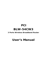
The controllers equipped with the Ethernet unit operate as a server and constantly await
a connection request from the client (other party’s device such as a PC). Specific actions
are then carried out when a request arrives from a client. So the controller cannot connect
to another server on its own.
Server
Client Client Client
IP address
192.168.0.3
192.168.0.5
192.168.0.10 192.168.0.11
192.168.0.12
Controller
+
Ethernet Unit
q
w
Functions as a server.
Performs specified
actions upon receiving
request from client.
Device such as PC is the client, connects to server and issues
commands to perform specified actions.
Ethernet
q Specify the IP address of controller to exchange data with and make the connec-
tion. (Above example shows the client 192.168.0.10 has specified the controller
192.168.0.5 and made a connection.)
w After making the connection, the controller runs a specific series of actions accord-
ing to instructions from the client.
MEMO
MEMO
During multitasking by the client, several robots can be simultaneously connected to one
client unit.
Only one client can make a simultaneous connection to one controller unit.
Settings such as of the IP address and subnet are made from the TPB.

10
CHAPTER2 Ethernet Unit
2-3 How to connect to Ethernet
The Ethernet unit employs 10BASE-T specifications, so the controller connects by a
cable to the HUB.
Use UTP cables (unshielded twisted-pair cables) or STP cables (shielded twisted-pair
cables) for category 3 or higher, with straight-through wiring specifications.
To connect to the Ethernet, insert the cable with modular jack into the modular connector
on the controller until you hear a click. Insert the other end of the cable into the modular
connector on the HUB.
Fig. 2-1 Connecting to Ethernet
!
CAUTION
We use an FL HUB (made by Phoenix Contact) to check operation. Using this
HUB is recommended if constructing your own system.
HUBs generally available on the market are not designed for use in locations such
as factories, so some HUBs are vulnerable to external noise. Please acknowledge
beforehand that operation cannot be guaranteed if other types of HUBs are used.
Always be sure to use a HUB with high noise resistance when connecting to the
controller.
!
CAUTION
The maximum cable length between the HUB and controller is 100 meters.
Before connecting the HUB and controller always refer to the instruction manuals
for the device used by the other party and peripheral equipment such as the HUB.
If the HUB communication mode can be set manually, then set to 10Mbps/Half
Duplex.
MEMO
MEMO
Using a straight-through cable is recommended when connecting to the other party’s
device by way of the HUB. You can connect directly to the other party’s device without
the HUB by using a crossover cable but communication may sometimes not be possible
due to the type of LAN adapter used by other party’s device.
Controller
HUB
UTP (STP) straight-through cable

11
CHAPTER2 Ethernet Unit
2-4
Making system settings for the controller (server)
A minimum of IP address, subnet mask and gateway settings must be made so that the
controller will be correctly identified and acknowledged on Ethernet.
These settings are made from the TPB and enabled after the controller is restarted.
2-4-1 Validating the Ethernet unit
Before the Ethernet unit can be used, it must first be set as follows, to allow it to be
identified by the controller.
1) Press
F3
(SYS) on the initial menu
screen.
2) Press
F4
(next) to switch the function
display and then press
F2
(OPT).
3) Press
F1
(DEV).
4) The current Ethernet unit identity status
appears on the display.
Using the number keypad, enter “1” to
make the Ethernet unit identifiable from
the controller or enter “0” to prevent it
being identified from the controller, and
then press the
key.
5) The screen returns to the previous display
in step 4.
[MENU]
select menu
1EDIT2OPRT3SYS 4MON
[SYS]
select menu
1SAFE2OPT 3UTL 4next
[SYS-OPT]
select menu
1DEV 2MAC 3VER 4next
[SYS-OPT-DEV]
Ethernet=
0
0:invalid 1:valid
[SYS-OPT-DEV]
Ethernet=
1
0:invalid 1:valid

12
CHAPTER2 Ethernet Unit
2-4-2 Setting the IP address
This following explains how to set the IP address.
The IP address is a number unique to each device and identifies that device from among
many other devices connected on the network. The IP address of one device must not be
the same number as another device so use caution when setting the IP address.
1) Press
F3
(SYS) on the initial menu
screen.
2) Press
F4
(next) to switch the function
display and then press
F2
(OPT).
3) Press
F4
(next) again and then press
F1
(IP).
4) The currently set IP address is now dis-
played. To change it, enter the new IP
address with the number pad keys. (To
move the cursor to right and left between
periods, use the
X
+
Z
or
X
-
Z
keys.)
When completely finished making the
new IP address entry, press the
key.
5) The screen returns to the previous display
in step 4.
[MENU]
select menu
1EDIT2OPRT3SYS 4MON
[SYS]
select menu
1SAFE2OPT 3UTL 4next
[SYS-OPT]
select menu
1IP 2MASK3GWAY4next
[SYS-OPT-IP]
IP address
=
192.168. 0. 2
[SYS-OPT-IP]
IP address
=
133.210.201.100

13
CHAPTER2 Ethernet Unit
!
CAUTION
When connecting the controller on an already existing network, always check with
the network supervisor before making IP address, subnet mask and gateway set-
tings.
MEMO
MEMO
The IP address is separated into network address and host address sections. The network
address section is extracted from the IP address by AND processing with the subnet
mask. The remaining portion is the host address section. Devices belonging to the same
network must all be set to have the same network address. The host address, however,
should be different for every device and set so that no two devices have the same number.
The first and the last host address numbers are reserved for the system so be sure not to
set these as the IP address.
When the IP address for example is 192.168.0.10 and the subnet mask is 255.255.255.0,
the network address section is found to be 192.168.0 and the host address section to be
10 by means of AND processing with the subnet mask. In this case, the network address
section of all other devices belonging to that network must all be 192.168.0. The host
address section of those other devices on the other hand, must be set to a number other
than 10. The number 0 and 255 are reserved, so do not use them for setting the host
address.
So when a device having an IP address of 192.168.0.10 and a subnet mask of 255.255.255.0
belongs to a particular network and you want to add another device to that network, then
you would assign IP addresses from among 192.168.0.1 to 192.168.0.9 and 192.168.0.11
to 192.168.0.254.
MEMO
MEMO
The Ethernet unit is not usable with IP address auto-acquisition functions such as DHCP
and BOOTP. You must set the IP address manually.

14
CHAPTER2 Ethernet Unit
2-4-3 Setting the subnet mask
This following explains how to set the subnet mask.
The subnet mask is a numerical address used to subdivide the network into smaller parts.
1) Press
F3
(SYS) on the initial menu
screen.
2) Press
F4
(next) to switch the function
display and then press
F2
(OPT).
3) Press
F4
(next) again and then press
F2
(MASK).
4) The currently set subnet mask is now dis-
played. To change it, enter the new subnet
mask with the number pad keys. (To move
the cursor to right and left between peri-
ods, use the
X
+
Z
or
X
-
Z
keys.)
When completely finished making the
subnet mask entries, press the
key.
5) The screen returns to the previous display
in step 4.
!
CAUTION
When connecting the controller on an already existing network, always check with
the network supervisor before making IP address, subnet mask and gateway set-
tings.
[MENU]
select menu
1EDIT2OPRT3SYS 4MON
[SYS]
select menu
1SAFE2OPT 3UTL 4next
[SYS-OPT]
select menu
1IP 2MASK3GWAY4next
[SYS-OPT-MASK]
subnet mask
=
255.255.255. 0
[SYS-OPT-MASK]
subnet mask
=
255.255.255.240
/