Salsbury Industries 94368GY-U Installation guide
- Category
- AV equipment stands
- Type
- Installation guide

Plastic Lockers – 94000 Series
Models 94168 & 94368 Four Tier
Assembly Instructions
Thank you for selecting Salsbury 94000 Series Plastic Lockers. We are confident that the quality and construction of the lockers will prove to be a
good investment. These instructions are intended to assist you in the assembly of the lockers. Individual job conditions will dictate whether the
lockers must be anchored to the wall, the floor, or both. Please read the entire assembly instruction document before beginning assembly.
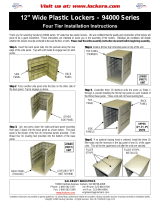
Step 1. Insert the back panel tabs into the pockets along the rear
edge of the side panel. Tap with soft mallet to engage two (2) latch
points.
SALSBURY I
NDUSTRIES
1010 East 62
nd
Street, Los Angeles, CA 90001-1598
Phone: 1-800-562-5377 Int’l Phone: 323-846-6700
Fax: 1-800-562-5399 Int’l Fax: 323-846-6800
Installation instructions are provided as general guidelines. It is advised that a professional installer be consulted. Salsbury Industries assumes no product assembly or installation liability.
Copyright © 2010 Salsbury Industries. All rights reserved. (Rev. 04, 7/22/2010) Page 1 of 3
Step 2. Press another side panel onto the tabs on the other side of
the back panel. Tap to engage as above.
Step 3. Join and press down the sides-and-back-panel assembly
from step 2 above into the base panel as shown below. The base
panel is the thicker of the five (5) horizontal panels provided. Then
thread four (4) leveling feet provided into the bottom of the base
panel.
Step 4. Install a thinner top horizontal panel on top of the unit.
Step 5. Assemble three (3) identical units the same as Steps 1
through 4, except installing the thinner top panel on each instead of
the thicker base panel. These units will not have leveling feet.
Step 6. If no optional sloping hood is ordered, install the three (3)
filler strips into the recesses in the top panel of one (1) of the upper
units. This will be the uppermost unit after the units are stacked.
SIDE
PANEL
BACK
PANEL
OTHER
SIDE
PANEL
BASE PANEL
(
THICKER
)
SIDE
PANELS
TOP
PANEL
BACK
PANEL
LOWER
(FIRST)
UNI
T
UPPER
(2
nd
, 3
rd
, 4
th
)
UNITS
LEVELING FEET
(NOT SHOWN)
TOP PANEL
(
THINNER
)
LOWER
(FIRST)
UNI
T
FILLER
STRIPS
FILLER STRIPS
INSTALLED

Plastic Lockers – 94000 Series
Models 94168 & 94368 Four Tier
Assembly Instructions
Step 7. Stack the three (3) upper units onto the lower unit. Press all
units firmly together. Use a mallet if necessary.
SALSBURY INDUSTRIES
1010 East 62
nd
Street, Los Angeles, CA 90001-1598
Phone: 1-800-562-5377 Int’l Phone: 323-846-6700
Fax: 1-800-562-5399 Int’l Fax: 323-846-6800
Installation instructions are provided as general guidelines. It is advised that a professional installer be consulted. Salsbury Industries assumes no product assembly or installation liability.
Copyright © 2010 Salsbury Industries. All rights reserved. (Rev. 04, 7/22/2010) Page 2 of 3
Step 8. Install screws and hole covers where side panels join to top
panels and base panel. There are 18 screws and hole covers on
each of the two sides of the assembly (36 in total).
Step 9. Attach the plastic oval lock plate to the front of the four (4)
doors with two (2) screws from the rear of the door. Insert the
stainless steel hasp through hole in front of doors making sure cutout
is facing downward. Secure by threading nut provided onto it from
rear. Insert lock knob through hasp from front of door making sure
hole in lock knob is facing downward. Attach cam to rear of lock
knob shaft with screw provided. Be sure the cam is pointing toward
the outside of the door and is properly engaged with the square shaft
end of the lock knob.
PANEL WITH
FILLER STRIPS
(IF NO OPTIONAL
SLOPING HOOD)
SCREW
Step 10. Fasten the eight (8) hinges (two (2) for each of the four (4)
doors) provided in the hardware package securely to each hinge
position with the screws provided as shown below. Fasten each of
the four (4) doors to the appropriate pair of hinges.
BASE PANEL
(THICKER)
CAM
LOCK
PLATE
HASP
LOCK
KNOB
NUT
ALL
UNITS
STACKE
D
SCREWS
(2)
NAMEPLATE
(
OPTIONAL
)
HOLES
SCREWS
COVERS
DOOR
HINGE

Plastic Lockers – 94000 Series
Models 94168 & 94368 Four Tier
Assembly Instructions
SALSBURY INDUSTRIES
1010 East 62
nd
Street, Los Angeles, CA 90001-1598
Phone: 1-800-562-5377 Int’l Phone: 323-846-6700
Fax: 1-800-562-5399 Int’l Fax: 323-846-6800
Step 11. Slide the shelves (optional) into the slots in the locker side
panels. There are three (3) slots available for shelves in each of the
four (4) compartments.
Step 14. If
two (2) or more lockers are to be installed side by side,
the lockers should be fastened together with the four (4) nuts and
long screws provided. Select any two (2) holes toward the front and
any two (2) holes toward the rear. The illustration below shows the
16 holes that are available. The lower illustration shows the inside
view of a hole and screw.
Installation instructions are provided as general guidelines. It is advised that a professional installer be consulted. Salsbury Industries assumes no product assembly or installation liability.
Copyright © 2010 Salsbury Industries. All rights reserved. (Rev. 04, 7/22/2010) Page 3 of 3
Step 12. Install the sloping hood (optional) to the top of each locker
column by aligning six (6) locating tabs with the topmost panel.
Press locating tabs into place. Illustration shows sloping hood before
pressing tabs into place. Plastic filler strips shown in step 6 are not
required on units with a sloping hood and can be discarded.
SLOPING
HOOD
SHELF
INSIDE VIEW
OF HOLE
AND SCREW
Step 13. Install placards (optional) in the indentation near the top of
each door.
The assembly of the plastic lockers is now complete.
-
 1
1
-
 2
2
-
 3
3
Salsbury Industries 94368GY-U Installation guide
- Category
- AV equipment stands
- Type
- Installation guide
Ask a question and I''ll find the answer in the document
Finding information in a document is now easier with AI
Related papers
-
Salsbury Industries 81015TN Operating instructions
-
Salsbury Industries 13168LGT Installation guide
-
Salsbury Industries 8274GRY-U Installation guide
-
Salsbury Industries 9274GRY-U Installation guide
-
Salsbury Industries 98368BL-A Installation guide
-
Salsbury Industries 92368GY-A Installation guide
-
Salsbury Industries 95168BL-A Installation guide
-
Salsbury Industries 9048TAN-U Installation guide
-
Salsbury Industries 93368BL-U Installation guide
-
Salsbury Industries 9274TAN-A Installation guide
Other documents
-
 Salsbury Built-In Keyed Lock Installation guide
-
Edsal WC-1 Operating instructions
-
 Salsbury Built-In Combination Lock Installation guide
-
 Salsbury 12" Wide Four Tier Plastic Locker Installation guide
-
 Salsbury 12" Wide Double Tier Plastic Locker Installation guide
-
 Salsbury 12" Wide Eight Tier Plastic Locker Installation guide
-
 Salsbury 12" Wide Five Tier Plastic Locker Installation guide
-
 Salsbury 12" Wide Ten Tier Plastic Locker Installation guide
-
 Salsbury 12" Wide Triple Tier Plastic Locker Installation guide
-
Bradley Lenox Cubby Series Installation guide


