Page is loading ...

One World. One Smart Choice.
™
AB -HDRX
HD/SD COFDM Dual Diversity Receiver
Owner’s Manual
A7595-0438 Rev A
®

1
TABLE OF CONTENTS
2 IMPORTANT
3 INTRODUCTION
4-9 QUICK SET-UP
10-12 SPECIFICATIONS
13-14 THEORY OF OPERATION
15 WARRANTY

2
IMPORTANT:
This device complies with part 15 of the FCC Rules. Operation is subject to the following two conditions: (1) This device may not
cause harmful interference, and (2) this device must accept any interference received, including interference that may cause
undesired operation.”

3
INTRODUCTION:
The AB-HDRX is a compact, narrowband COFDM microwave receiver that utilizes dual antenna diversity for robust, error free signal reception.
The AB-HDRX is ideal for applications requiring a full featured high performance HD or SD receiver housed in a compact enclosure. ASI, HD-SDI,
SD-SDI, Composite video, User Data and streaming video outputs are available from the AB-HDRX. The AB-HDRX uses industry standard output
connectors for compatibility with a wide range of AV equipment.
Though the unit ships pre-congured, a graphical user interface that runs on a Windows PC is available to modify the operating parameters. While
this manual contains basic information about the operation of the AB-HDRX, the programming of the unit (including preset conguration) via the
AB Control Software is not covered. Please refer to the AB Control Software Manual for detailed information on how to program and congure the
unit.

4
AB-HDRX Quick Set-up
• Remove AB-HDRX Receiver from the case.
• Attach AB-HDRX to the Manfrotto Magic Arm using the tripod mounting bracket.
• Connect Video output as needed (BNC connector).
• Connect Audio output as needed (RCA jacks).
• Connect RX antennas (larger sector directional) to the RF Inputs (N-Type).
• Aim directional sector antennas (marked “Front”) in the general area of AB-HDTX operation.
• Connect your Anton/Bauer Logic Series® battery to the AB-HDRX via the Gold Mount®.
• Select an AB-HDRX preset using the set button.
Connecting External Signals
The AB-HDRX Receiver has the following major output interfaces:
• RS-232 Serial Port
• Left and Right Audio Outputs
• Composite Video Output (not down converted from HD)
• ASI Video Output
• SDI Output for HD-SDI and SD-SDI Video
• Ethernet
• User Data
Audio and Video
Connect the desired Audio and Video outputs to A/V monitoring devices with appropriate cables. The AB-HDRX has RCA jacks for audio and
75ohm BNC connectors for Composite Video, SDI and ASI.
Power
The AB-HDRX may be powered by the following:
• DC Power – Anton/Bauer Logic Series battery
• AC Power – Anton/Bauer Tandem 70 charger connected to AC power
RS232 Control and User Data
If desired, connect a suitable cable to the 9 pin D Remote/User Data connector per the pinout in the Specications chapter. Cables are
available standard in the kit.
ASI Out
If required, connect a suitable ASI output cable (75Ω BNC).
Antennas
Connect antennas directly to the N-Type RF input connectors. Antennas are sector antennas with a 110° azimuth. Aim the antennas in the
direction of the AB-HDTX transmission (input labeled ‘Front”).
WARNING: If cabling the AB-HDRX directly to a transmitter (e.g. for testing) you must use in-line RF attenuators. 50dB minimum recommended. Pre-Congure
the AB-HDRX user options.
QUICK SET-UP

5
QUICK SET-UP
Figure 1: AB-HDRX Antenna Connectors
The AB-HDRX has a wide range of programmable settings. Before using the AB-HDRX in your application, you should pre-congure it to for
the settings you want to use in your application. Settings are selected and congured using the AB Control Software. Please refer to the AB
Control Software Manual for details.
Using the AB-HDRX to Receive Audio and Video
The AB-HDRX receives and demodulates COFDM radio signals from the AB-HDTX. It then decodes the MPEG4 transport stream for output.
The dual antenna diversity feature of the AB-HDRX is used to maximize the robustness of video reception. The primary goal of dual antenna
diversity is to enable the user to prevent line of site obstruction on the transmission path from causing receiver errors to occur. By separating
the antennas, the user has two chances to receive the signal properly, regardless of obstructions between the transmitter and AB-HDRX
antennas. Properly directing your antenna to the transmit source is key obtaining the best range possible.
Video may be viewed on a monitor, which accepts SD Composite video, or SDI. Encoded video is also included in the transport stream on the
ASI output, and must be decoded using an MPEG4 decoder prior to viewing on a monitor.
Audio can be output to a recorder or amplier. Audio is also embedded in SDI outputs and included in the transport stream on the ASI output.
Streaming video and audio may be output via a laptop or PC with a compatible MPEG4 decoder program.
Verify Operation
After installing the AB-HDRX, power up the receiver by attaching a Logic Series battery and your overall system. The LED’s on presets 1-4 will
sequentially illuminate until boot up is complete.
Verify operation of the AB-HDRX by using the following methods:
• Use a video monitor to view SD Composite video (NTSC or PAL, as appropriate).
• Display video on equipment with ASI or SDI input connectors. This may include video analysis equipment or PC’s with ASI or SDI input
cards used for video storage and editing.
• To stream video over IP use the Ethernet connection to a PC or laptop running a compatible MPEG4 audio and video decoder program.
Streaming Video over IP/Ethernet
The AB-HDRX is pre-congured to stream video over IP on its Ethernet port. To stream video over IP use the Ethernet connection to a PC or
laptop running a compatible MPEG4 audio and video decoder program.

6
QUICK SET-UP
Streaming Modes
There are three selections for streaming modes:
• Off - The unit does not stream in the “Off” mode.
• RTSP - In the RTSP mode the video streaming is sent only as clients request it. This can occur via unicast (single client) or multicast
(multiple client) calls.
• Manual - Streaming is always on in the manual mode and can be sent to a single client or multiple clients using a multicast destination
address.
RTSP Streaming Modes
There are four supported streaming modes from the RTSP server.
• Unicast, RTP
• Unicast, UDP
• Multicast, RTP
• Multicast, UDP
There is no need to set any parameters in this mode as the RTSP server takes care of this automatically.
RTSP Mode Set-up
Unicast, RTP - This mode will stream the data packets encapsulated by an RTP header to a single client only.
Use the AB Control Software to download and open the preset le for editing.
Set the mode to RTSP as shown in Figure 2.
Figure 2: Preset le for Video Streaming Parameters
Upload the preset le into the radio
The default network URL for this method is rtsp://<device ip address> (Default 192.168.010.035)
• Unicast, UDP - This method will stream the data packets without the RTP header to a single client. The default network URL for this
method is rtsp://<device ip address>/unicast/udp
• Multicast, RTP - This method will stream the data packets with the RTP header to multiple clients. The default network URL for this
method is rtsp://<device ip address>/multicast
• Multicast, UDP - This method will stream the data packets without the RTP header to multiple clients. The default network URL for this
method is rtsp://<device ip address>/multicast/udp

7
QUICK SET-UP
Streaming in the Manual Mode
This mode requires manual conguration of the streaming parameters in order to replicate the four types of streaming listed above. The data
packets are streamed constantly. Set the destination port to the port that your application uses to receive video. Set your PC network adapter
to a static IP address with the same subnet as the AB-HDRX unit.
Unicast, RTP (manual mode)
• Set the Streaming mode to “Manual” as shown in Figure 3.
• Set the Encapsulation type to RTP-TS
• Enter the destination address of your computer
Figure 3: Change the Streaming Mode to Manual
• Unicast, UDP (manual mode)
1. Set the Encapsulation type to UDP-TS
2. Enter the destination address of your computer
• Multicast, RTP
1. Set the encapsulation type to RTP-TS
2. Enter a multicast address for the destination address
• Multicast, UDP
1. Set the encapsulation type to UDP-TS
2. Enter a multicast address for the destination address

8
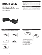
Figure 4: Output Connectors
Item Description Connectors
Left, Right Audio Line Outputs 75 Ohm RCA
SDI HD-SDI or SD-SDI Output BNC
Video Composite Video (PAL or NTSC) BNC
ASI Encoded Video Output BNC
DC In Via Anton/Bauer Logic Series Battery Gold Mount
Ethernet Port 100mbps LAN Interface RJ45
Remote / User Data RS-232 Connector DB-9
LEFT RIGHT VIDEO SDI
ASIREMOTE/USER DATA
QUICK SET-UP

9
QUICK SET-UP
Local User Interface
The AB-HDRX has two control buttons and several status LED’s on the front panel. Any changes made via a remote control interface will be reected by the front
panel LED’s.
The AB-HDRX can be pre-congured using the programmable serial interface and then quickly changed between preset modes using the “Set” pushbutton.
AB-HDRX Receiver User Interface
Control/Indicator Description
Set Button
Advances the unit through the
presets. The 1-16 LED’s indicate in
GREEN, which preset is currently
active.
AB-HDRX
SET
SCAN
System Fault
Signal Strength
RX Lock
Streaming
Decoder
5
6
7
8
16
15
14
13
1 2 3 4
12 11 10 9
SCAN (future feature)
Scans available presets until it
locks on an incoming signal.
RSSI
LED’s will light to provide a
Received Signal Strength
Decoder Decoder Operating
Streaming
Indicates that the unit is streaming
video through the Ethernet port.
Rx Lock
When YELLOW, the demodulator
is locked
System Fault
Normally OFF. If an Alarm is
present, the LED will be RED.
Figure 5: AB-HDRX Receiver User Interface

10
SPECIFICATIONS
Specications
Frequency Bands and RF Performance
Base Part Number Frequency (GHz) Power Consumption
58AB-HDRX 5.725-5.850 9 Watts Typical
Tuning step size 250 KHz
Frequency stability ± 10ppm
Modulation Modes
Modes are auto detected within modulation format
Format: COFDM (DVB-T)
Carriers: 2K
Constellation: QPSK, 16QAM
Code Rate: 1/2, 2/3, 3/4, 5/6, 7/8
Guard Interval: 1/32, 1/16, 1/8, 1/4
Bandwidth: 6 MHz, 8 MHz
Diversity
Dual Receivers
Channels: 2 input Maximum Ratio Combining
Video
Standard: MPEG-4 Part 10 / H.264 AVC and MPEG2
Video Coding: AVC
Video Input: Composite and SDI
SD-SDI input: ANSI/SMPTE 259M
HD-SDI Input: ANSI/SMPTE 292M
Formats
SD: NTSC 720 x 480 (4:2:0)
PAL: 720 x 566 (4:2:0)
HD: See table below
Remote Control / User Data Pinout
Pin Function Notes
1 N/C
2 RX / IN A Remote Control
3 TX / OUT A Remote Control
4 N/C
5 Ground Ground
6 TX / OUT B User Data
7 RX / IN B User Data
8 N/C
9 N/C

11
SPECIFICATIONS
Standard Rate Mode Latency
720 59.94 p 4 frames
720 50 p 4 frames
720 29.97 p 4 frames
720 25 p 4 frames
720 24 p 4 frames
720 23.98 p 4 frames
1080 50 i 4 frames
1080 59.94 i 4 frames
1080 29.97 p 4 frames
1080 25 p 4 frames
1080 24 p 4 frames
1080 23.98 p 4 frames
1080 29.97 psf 5 frames
1080 25 psf 5 frames
1080 24 psf 5 frames
1080 23.98 psf 5 frames
Audio
Audio Coding: ISO/IEC 11172-3(Layer II)
Audio Sample Rate: 48Khz
Audio Channels: 1 Stereo, 2Mono Standard
Audio Output Levels: Direct line output with adjustable gain
Embedded Audio: Available in SDI as embedded audio
System
Video Present: Remote Standby/Test Generator Selectable
Latency (*using AB-HD Transmitter): 4 frames in Low Latency Mode for all formats except
PSF
5 frame in Low Latency Mode for PSF formats
ASI Output: Auto output rate follows modulation or xed output
user selectable (PCR Retime stamp)
User Data: RS232 Side channel (300-115K Baud)
Ethernet: 100 Mbps Ethernet interface
Remote Control: Via LAN and/or PC GUI
Streaming Video: Streaming MPEG-TS over UDP/RTSP
Power Requirements
Input Range: DC: +9 to +28
Power Consumption: 9W typical

12
SPECIFICATIONS
Physical Characteristics
Size (including connectors): 3.69” x 6.75” x 2.31”
Volume (including connectors); 57.5 in³
Weight: 1.4 lbs (620 grams)
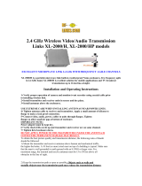
Figure 6: AB-HDRX Outline Drawings (Dimensions in Inches)
3.69
4.11
6.75
1.75
3.69
2.31

13
THEORY OF OPERATION
Functional Block Diagram
Major blocks in the AB-HDRX diagram include:
• Dual Antenna Inputs
• Dual Microwave Receiver and COFDM Demodulator Circuits
• Dual Input Maximal Ratio Combining Circuit
• MPEG4 Video Decoding Circuit
• Video Output Interfaces: ASI, SDI, and Composite Video
• Left and Right Audio Output Interfaces
• Preset Selection and Status Monitoring User Interface
• Programmable Serial Interface and Internal Control CPU With Flash Memory
• Interface For Firmware Upgrades
• Power Circuitry
Pre RF
Filter
Pre RF
Filter
Narrow
Band
IF
High
Dynamic
LNA
Antenna
COFDM
Demodulator
MRC
Combiner
Decryption
Ethernet
MEGTSoIP
Pre RF
Filter
Pre RF
Filter
Narrow
Band
IF
High
Dynamic
LNA
Antenna
COFDM
Demodulator
Figure 7: Internal Block Diagram
Dual Antenna Inputs
The AB-HDRX has two N-Type antenna input connectors. The input impedance of the antenna connectors are 50 ohms.
The frequency band supported by the antenna connectors are labeled next to the antenna inputs.
Dual Microwave Receiver COFDM Demodulator Circuits
The AB-HDRX is capable of receiving COFDM transmissions from compatible products. Each antenna input is ltered and amplied by a
low noise amplier. The output of the amplier is ltered again at the output of the RF receiver circuitry. The receiver mixer down converts the
received signals to the internal IF frequency.
The COFDM demodulator is programmable to support transmission modes offering different data rates (Refer to Chapter 4 for more
information). The output of the COFDM demodulator circuits contains transport streams carrying audio, video, and user data.

14
THEORY OF OPERATION
Maximal-Ratio Combining Circuit
This feature enhances the robustness of the receiver when line of site obstructions occur in the transmission path.
MPEG4 and MPEG 2 Decoder
The AB-HDRX contains a built-in auto-detect MPEG4 (H.264 part 10) compliant and MPEG2 decoder. The decoder audio and video output is
available on the SDI output jack. Both HD-SDI and SD-SDI are output on the SDI jack.
Video Outputs
Video output jacks include:
ASI – Encoded transport stream
SDI – HD-SDI and SD-SDI audio and video
Composite Video – The AB-HDRX composite video output circuit automatically outputs any SD video into either NTSC or PAL.
Audio Outputs
The AB-HDRX has left and right audio line output jacks. Stereo audio is also part of the ASI and SDI video outputs. The Audio output jacks are
RCA connectors.
User Data Output
A data channel is transmitted with the audio and video information. Access of the data channel is through the RS-232 serial interface output
connector. The baud rate and other RS-232 parameters are programmable.
Video over IP Encapsulation for Streaming Video
The AB-HDRX features a 100 Mbps Ethernet LAN interface for streaming video over IP. This feature allows received video to be viewed
remotely using MPEG4 decoder software on a personal computer.
Local User Interface
If you commonly use several congurations in the eld, the faceplate LED preset settings and “Set” selector button provide a quick way to
change pre-programmed congurations. Status information is also presented by LED’s. Refer to page 9 for more information.
Remote Control and Firmware
Remote Control via Ethernet
An Ethernet port allows remote control of all conguration options, as well as monitoring of internal status and settings.
The AB Control Software is available for controlling the unit via the Ethernet port. Any Windows compatible computer running Windows XP or
Windows 7 with 500 MB of memory and 1 GHz Pentium or above can be used. Refer to the AB Control Software Manual for more information.
Remote Control via RS-232
An RS-232 command set is implemented to allow remote control of all conguration options, as well as monitoring of internal status and
settings. Commands and responses are sent via the RS-232 serial interface on the 9-pin connector.
The AB Control Software is available for controlling the unit via the RS-232 serial interface. Any Windows compatible computer running
Windows XP or Windows 7 with 500 MB of memory and 1 GHz Pentium or above can be used. Refer to the AB Control Software Manual for
more information.
Firmware updates
Update unit rmware via the Ethernet interface. Contact Anton/Bauer Customer Support Group for additional details.

15
LIMITED WARRANTY
This two (2) year limited warranty for the product specied in this
document (“Product”) is given by Anton/Bauer, Inc. (“Anton/Bauer”),
14 Progress Drive, Shelton, Connecticut 06484. If you (the purchaser
of the Product from Anton/Bauer, or the person for whom the Product
was purchased, if it was a gift) have any questions regarding Product
applications, Product specication, or to obtain warranty service on
this or any Anton/Bauer product, contact the company at the address
below.
THIS PRODUCT MUST BE REGISTERED WITH ANTON/BAUER
WITHIN 30 DAYS OF PURCHASE TO ASSURE WARRANTY
COVERAGE. TO REGISTER YOU MAY EITHER:
(1) MAIL WARRANTY REGISTRATION CARD or
(2) REGISTER ON LINE AT www.antonbauer.com
The liability of Anton/Bauer hereunder is expressly limited to a claim
for repair or replacement of the Product or as otherwise stated
herein at Anton/Bauer’s sole discretion. Notice of any claim under
this warranty shall be delivered to Anton/Bauer during the period of
the warranty and the Product shall be returned with its packaging
promptly, at your expense, to an Anton/Bauer Customer Support
Center or to the address above. Upon receipt of the Product and
a record of your compliance with the conditions of this warranty,
Anton/Bauer will repair or replace the Product and return it to you, or
issue a credit, as applicable. You are responsible for all shipping and
handling charges to and from authorized facility.
THIS WARRANTY DOES NOT APPLY TO AND IS VOID IN THE
CASE OF DEFECTS OR DAMAGE RESULTING FROM ACCIDENTS,
DISASTER, NEGLECT, MISUSE, IMPROPER INSTALLATION,
IMPROPER OR UNAUTHORIZED SERVICE OR MAINTENANCE,
UNAUTHORIZED REPLACEMENT PARTS OR ATTACHMENTS;
OR DYSFUNCTION OR MALFUNCTION OF, OR CAUSED BY, ANY
OTHER PRODUCT OR DEVICE. Misuse includes any use of the
Product in other than its intended application, including the
use of this Product with any charging device or accessory not
manufactured by and/or specied by Anton/Bauer. This warranty
does not cover, and Anton/Bauer assumes no responsibility for,
any equipment or devices used in conjunction with the Product.
ANTON/BAUER DISCLAIMS ANY LIABILITY FOR INCIDENTAL OR
CONSEQUENTIAL DAMAGES FOR BREACH OF ANY WRITTEN
OR IMPLIED WARRANTY OF THE PRODUCT. UNDER NO
CIRCUMSTANCES WILL ANTON/BAUER BE RESPONSIBLE FOR ANY
SPECIAL, INCIDENTAL OR CONSEQUENTIAL DAMAGES.
This Warranty is to be construed and enforced in accordance with the
law of the State of Connecticut, including the provisions of the Uniform
Commercial Code as adopted and from time to time amended in the
State of Connecticut, and not the Convention for the International
Sale of Goods. This choice of Connecticut law is exclusive of any
Connecticut law that would require reliance on any law foreign to
Connecticut. Should any action of law or in equity be brought by any
person under this Warranty, such action shall be brought only in the
United States District Court for the District of Connecticut, or in any
Superior Court in Faireld County, Connecticut, USA. Some states do
not allow limitations on how long a warranty lasts, so the time period
limitation herein may not apply to you. Some states do not allow the
exclusion or limitation of incidental or consequential damages, so the
above limitation or exclusion may not apply to you. This warranty gives
you specic legal rights and you may have other legal rights which may
vary from state to state.
Use of unauthorized equipment in conjunction with Anton/Bauer
products constitutes misuse under our warranties and may limit or
void those warranties. Anton/Bauer does not authorize, condone,
recommend, or otherwise assume any liability or responsibility resulting
from the use of any battery, charger or accessory made by Anton/Bauer
manufacture with any battery, charger or accessory not manufactured,
produced or sold by Anton/Bauer. Anton/Bauer only authorizes the
use of original Anton/Bauer product with this product. Use only original
Anton/Bauer equipment with this product.

16
Anton/Bauer
A Vitec Group brand
The following are trademarks of Anton/Bauer, Inc.:
Anton/Bauer, Anton/Bauer logo and parallelogram design, Aspekt, Automatique,
DataTap, DIONIC, Elipz, Egripz, Elightz, Essentialz, Gold Mount, HubZ, HyTRON, Impac,
Interactive and design, LifeSaver, Logic Series, Logic Series Logo, Maxx man logo design,
Nexus, PowerStrap, Proformer, Probe, ProPac, RealTime, Satellight, Snap-On, Stasis, Stasis
Flex, Tandem, TrimPac, Ultrakit, Ultralight, “One World. One Smart Choice”, “The power
behind the best cameras capturing the best images in the world.”, “The quality standard
of the video industry”, “The worldwide standard”, and “There should always be choices. It
makes it easier to recognize the best.”
Lexan is a registered trademark of G.E. Company Corp.
Cordura is a registered trademark of E.I. duPont de Nemours
Anton/Bauer, Inc.
World Headquarters
14 Progress Drive, Shelton, CT U.S.A.
Tel (203) 929-1100 or (800) 541-1667
Fax (203) 929-9935
support@antonbauer.com
Anton/Bauer Europe, B.V.
Eurode Business Center, Eurode - Park 1-2
6461KB Kerkrade, The Netherlands
Tel (+31) 45 5639220
Fax (+31) 45 5639222
eurosupport@antonbauer.com
www.antonbauer.com
Anton/Bauer, Inc. - Signapore Oce
6 New Industrial Road, # 02-02 Hoe
Huat Ind. Bld., Singapore 536199
Tel (+65) 62975784
Fax (+65) 62825235
asia@antonbauer.com
/