Masport Tasman Series Owner's manual
- Category
- Barbecues & grills
- Type
- Owner's manual
This manual is also suitable for

PANTONE 648C
546565.A.3 - May 2019
www.masport.com
Part N
o
: 546565.A.3
Barbecues
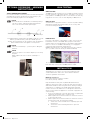
Masport 4/6 Burner Tasman Series
OWNER’S MANUAL
Please read these instructions carefully before assembly, to
reduce risk of fire, burn hazard or other injury.
Keep these instructions in a safe place for future use.
This manual covers the Masport 4/6 Burner Tasman Series barbecue.

CONTENTS
INTRODUCTION 3
SAFETY INFORMATION 3
SYMBOLS IN THIS OWNER’S MANUAL 3
IMPORTANT SAFETY INFORAMTION 3
WARRANTY INFORMATION 4
DISPOSAL OF PACKAGING 4
IMAGES 5
ASSEMBLY INSTRUCTIONS FOR BBQ 6
FOR MODELS WITH ROTISSERIE - ASSEMBLY INSTRUCTIONS 18
LEAK TESTING 18
INSTALLATION 18
OPERATION 20
TROUBLESHOOTING 22
EXPLODED VIEW - COMPONENT LIST 23
TECHNICAL DATA 26

3
546565.A.3 - May 2019
INTRODUCTION
This product has many features for making its use more pleasant
and enjoyable. Safety, performance, and dependability have been
given top priority in the design of this product making it easy to
maintain and operate.
This product is only intended for use outdoors. It is intended for
blowing light debris including leaves, grass and other garden refuse.
It is intended to vacuum and mulch light debris as above and collect
in the debris bag. It is not designed to suck or vacuum water or
other liquid.
SAFETY INFORMATION
KEEP THE INSTRUCTIONS IN A SAFE PLACE FOR FUTURE
USE.
WARNING!
DO NOT OPERATE THIS BBQ BEFORE IT
HAS BEEN ASSEMBLED CORRECTLY AND
YOU HAVE READ AND UNDERSTOOD THESE
INSTRUCTIONS.
READ
These instructions are intended as a general
guide and do not supersede national or local
codes in any way. Contact local authorities for
clarity of laws relating to the operation of this
appliance.
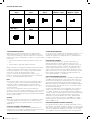
SYMBOLS IN THIS OWNER’S MANUAL
Possible hazard or hazardous situation.
Not observing this instruction can lead to injuries or cause
damage to property.
Important information on proper handling.
Not observing this instruction can lead to faults in
the BBQ.
User information. This information helps you to use all the
functions correctly.
Failure to follow these instructions could result in fire or
explosion which could cause property damage, personal
injury or death.
Accessible parts may be very hot. Keep young children away
from the hot appliance at all times (even while cooling down).
Some parts of this grill may have sharp edges especially as
mentioned in this manual! Wear suitable protective gloves if
necessary.
Assembled parts sealed by the manufacturer must not be
altered by the user. Any modification of the appliance by
unauthorised persons may be dangerous.
WARNING!
FOR OUTDOOR USE ONLY
WARNING!
To reduce the risk of fire, burn hazard or other injury,
read the instructions carefully and be sure your
appliance is properly installed and assembled.
DANGER!
If you smell gas:
1. Shut off gas to the appliance;
2. Extinguish any open flame:
3. Open lid;
4. If odor continues, keep away from the appliance
and immediately call your gas supplier or your fire
department
WARNING!
TO INSTALLER:
Test operation of the appliance and instruct the user
before leaving. Ensure the appliance is commissioned
correctly before handing over to the user.
WARNING!
The grill head is heavy and will require two or more
people to lift and position onto the grill cart when
assembly.
WARNING!
Do not try lighting this appliance without first reading the
“LIGHTING INSTRUCTION” section of this manual.
WARNING!
Conversion to natural gas only done by authorized
persons.
WARNING!
Always keep the electrical components in dry situation.
IMPORTANT SAFETY INFORAMTION
Please read and understand this manual fully before assembly and
use.
• The Manufacturer’s Warranty may be voided by the incorrect use
of this product.
• The Manufacturer or their Agents can accept no liability for the
unsuitability of, or any damage to, food that is cooked on this
appliance.
• Use the correctly specified fuel with this barbecue. Check with
your dealer for the specific fuel for which this barbecue has been
designed.
OWNER’S MANUAL
• The operator must understand all the safety requirements detailed
in this manual before using the barbecue.
• If you have any queries regarding these instructions, contact your
local dealer for clarification before you use your barbecue.
• The unit must be correctly assembled before use. Failure to follow
the manual’s instructions could result in serious damage or injury.
PERSONAL SAFETY
• The use of alcohol, prescription or non-prescription drugs may
impair the consumer’s ability to properly assemble or safely
operate this barbecue.
• The barbecue should be carefully checked for operational use
every time before use.
• Never try to move the barbecue when it is on, or before it has had
time to cool down.
• The person operating this barbecue should pay constant attention
to the food being cooked.

4
546565.A.3 - May 2019
• Do not leave the barbecue unattended when it is alight. The
person should remain at the barbecue at all times when it is
alight/cooking.
THIRD PARTY SAFETY
• The operator is responsible for the safety of all third parties while
the barbecue is in use.
• Onlookers should be kept a safe distance away from the
barbecue when it is in use.
• Keep children and animals well away while the barbecue is in use
and while it is cooling down.
LOCATION
• Do not use indoors. Barbecue units are designed for OUTDOOR
USE ONLY.
• Use in a weather-protected area, preferably under shelter.
• Ensure that the barbecue is on an even and secure surface before
operating. Use the castor locks if fitted to lock the wheels in
place.
• Do not use within one metre of any flammable surface of
structure.
BURN AWARENESS
• Parts of the barbecue do get extremely hot and could cause
serious burns – touch test the surface before applying a firm grip.
• The hood handle can become hot! Always wear cooking gloves
and long sleeves when handling hot components.
• If cooking with the hood closed, be very careful opening the hood,
a sudden rush of hot air could burn an unprotected arm.
GAS AWARENESS
• Ensure all gas couplings and hoses are in good condition and
have been correctly fitted.
• Leak test all gas lines and connections before use.
• Do not store flammable materials near this barbecue.
• Do not store spare LPG cylinders under or near this barbecue.
• Do not place or use aerosols near this barbecue.
• Do not store or use gasoline or other flammable vapours or liquids
in the vicinity of this barbecue.
• Ensure that the gas is turned OFF at the cylinder after use and
while the barbecue is unattended.
• When turning off the barbecue, shut off the gas at the supply
source before turning off all the burner controls.
• Do not lean over appliance when lighting.
• Do not use appliance with any cover on.
• Do not use plastic or glass utensils on the appliance.
• Do not dismantle control valves.
• Do not test for gas leaks with a naked flame.
• Do not modify the constructions of the appliance or the size of
any burner, injector orifice or any other components
• Do not obstruct any ventilation of the appliance.
• Do not allow the flexible gas supply hose or any electrical cord to
come in contact with any heated surface of the appliance.
• Do not use charcoal or any other solid fuel in this appliance.
• Do not disconnect any gas fittings while the appliance is in use.
• Do not use a rusty or dented gas cylinder with a damaged gas
valve.
• Do not fill the gas cylinder beyond 80% capacity.
• Do not store gas cylinders below ground level. ULPG is heavier
than air. Should a leak occur, the gas will collect and could ignite
due to presence of a flame or electric spark.
• Do not place articles on or against this appliance.
FOR YOUR SAFETY AND OTHERS
If you smell gas:
• Shut off the gas supply to the barbecue.
• Extinguish any open flame (candles, cigarettes, etc.)
• Clear the area to allow the unburned gas to dissipate.
• Be aware of the reason for the gas smell, address this before
continuing. Should the gas odour come from the LPG cylinder,
immediately contact the fire department from an elevated safe
distance.
• Connecting the gas cylinder to the barbecue, refer to that section
in the manual.
• Leak testing, refer to that section in the manual.
SAFETY EQUIPMENT
• When cooking with oil/grease, fire extinguishing materials should
be readily accessible.
• In the event of an oil/grease fire do not attempt to extinguish with
water or alcohol. Use type BC dry chemical fire extinguisher or
smother the fire with dirt, sand or baking soda.
RAIN HAZARD
In the event of rain while cooking with oil/grease, turn off the gas
supply and all burners, cover the barbecue as soon as possible.
Move people/animals away from around the barbecue. Do not
attempt to move the barbecue until it has cooled and can safely be
moved.
WARRANTY INFORMATION
WARRANTY
Refer to the warranty supplied with this BBQ. Should any part fail
due to defective workmanship or faulty materials within the specified
period from the date of purchase, Masport will replace or repair the
defective part free of charge. Refer to the warranty for details. Do
not use a BBQ that is unsafe.
LPG CYLINDER
The cylinder manufacturer/distributor is responsible for the safety
and performance of the LPG cylinder. This is not included in the
Masport BBQ warranty. Do not use a cylinder that is unsafe.
DISPOSAL OF PACKAGING
Remove all protective packaging including any protective film from
stainless steel surfaces.
Make sure you properly dispose of, or recycle the packaging
material where possible to comply with applicable waste disposal
laws in your area.

5
546565.A.3 - May 2019
IMAGES
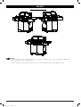
BG2294B-BL& BG2296B-BLAssembly
instructions
NOTE:
The following pages contain assembly instructions for various model options. Please ensure you identify your BBQ model so
that the correct instructions can be follwoed.
When assembling the cabinet, leave all of the screws loose until completey assembled, then tighten all screws.

6
546565.A.3 - May 2019
ASSEMBLY INSTRUCTIONS FOR BBQ
Product Description
Carton Identification
Product Part Number
Open the carton by removing the
shipping straps then slitting along both
ends. Cut the tape only by a small
amount in the middle, finish by lifting
the carton flaps with your hand.
Unpack the entire carton, this carton
will be used as a surface protector as
the cabinet is being built. Open the
carton as shown and place where the
BBQ will be assembled
NOTE:
Letters in the bracket after every screw, helps you identify the item number from the parts list on page 6, from the fastener kit.
Tools needed for assembly: Crosshead screwdriver, 10mm A/F Spanner
Before commencing assembly, open the cartons and lay all of the components on the floor. Familarise them against the parts list on page
21, as some of these instructions refer to this parts list.
NOTE:
When assembling the barbecue, ensure it is sitting on a flat surface.
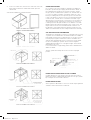
STEP 1. ATTACH CASTORS.
Use four M6*16mm screws (A), four M6 flat washers (D) and four M6 spring washers (E) to attach each castor onto the underside of the
Bottom panel (6)
(two castors without lock (23) at the front and two castors with lock (24) at the back).
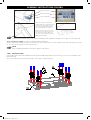
ASSEMBLY INSTRUCTIONS
Step 1 Attach Castors.
Use four M6*16mm screws (A), four M6 flat washers (D) and four M6 spring
washers (E) to attach each castor onto the underside of the Bottom panel (6)
(two castors without lock (23) at the front and two castors with lock (24) at the
back).
Step 2 Attach the Cart Side Panel.
Use two M6*12mm screws (B) to attach cabinet left side panel (7) and two more
screws to attach cabinet right side panel (8) both to the Bottom panel (2).
Note: Door hinge brackets should be at the front.

7
546565.A.3 - May 2019
STEP 2. ATTACH THE CART SIDE PANEL.
Use two M6*12mm screws (B) to attach cabinet left side panel (7) and two more screws to attach cabinet right side panel (8) both to the
Bottom panel (2).
Note: Door hinge brackets should be at the front
ASSEMBLY INSTRUCTIONS
Step 1 Attach Castors.
Use four M6*16mm screws (A), four M6 flat washers (D) and four M6 spring
washers (E) to attach each castor onto the underside of the Bottom panel (6)
(two castors without lock (23) at the front and two castors with lock (24) at the
back).
Step 2 Attach the Cart Side Panel.
Use two M6*12mm screws (B) to attach cabinet left side panel (7) and two more
screws to attach cabinet right side panel (8) both to the Bottom panel (2).
Note: Door hinge brackets should be at the front.
STEP 3. ATTACH BACK PANEL.
Attach the Back panel (9) to the cart with five M6*12mm screws (B).
NOTE:
Do not fully tighten the screws.
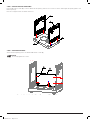
Step 3 Attach Back Panel.
Attach the Back panel (9) to the cart with five M6*12mm screws (B).
Note: Do not fully tighten the screws until all five screws are started.
Step 4 Attach the Cart Front Beam and Triangle Plates.
a) Attach cart front beam (10) to the cart side panels with four M6*12mm screws
(B).
b) Attach each triangle plate (21) to a side panel and to the Bottom panel with
four M6*12mm screws (B).

8
546565.A.3 - May 2019
STEP 4: ATTACH THE CART FRONT BEAM AND TRIANGLE PLATES.
a) Attach cart front beam (10) to the cart side panels with four M6*12mm screws (B).
b) Attach each triangle plate (21) to a side panel and to the Bottom panel with four M6*12mm screws (B).
Step 3 Attach Back Panel.
Attach the Back panel (9) to the cart with five M6*12mm screws (B).
Note: Do not fully tighten the screws until all five screws are started.
Step 4 Attach the Cart Front Beam and Triangle Plates.
a) Attach cart front beam (10) to the cart side panels with four M6*12mm screws
(B).
b) Attach each triangle plate (21) to a side panel and to the Bottom panel with
four M6*12mm screws (B).
STEP 5. ATTACH THE GREASE CUP BRACKET AND CABINET TOP PANEL.
a) Attach the grease cup bracket (27) to cabinet top panel (13) with five M4*8mm screws (G).
b) Attach the cabinet top panel assembly to left and right side panel. Push the side panels
outwards gently to fit the top panel. Use two M6*12mm screws (B) at the back and keep the
screws loose, then use three M4*8mm screws (G) at the front.
c) Tighten all screws
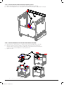
Step 5 Attach the Grease Cup Bracket and Cabinet Top Panel.
a) Attach the grease cup bracket (27) to cabinet top panel (13) with five M4*8mm
screws (G).
b) Attach the cabinet top panel assembly to left and right side panel. Push the
side panels outwards gently to fit the top panel. Use two M6*12mm screws (B) at
the back and keep the screws loose, then use three M4*8mm screws (G) at the
front.
c) Tighten all screws.
Step 6 Attach the Fat Tray Brackets
Attach the left and right Fat tray Brackets (15/ 16) to the left and right side panels
with two M6*12mm screws (B) on each side, as shown.

9
546565.A.3 - May 2019
STEP 6. ATTACH THE FAT TRAY BRACKETS.
Attach the left and right Fat Tray Brackets (15/16) to the left and right side panels with two M6*12mm screws (B) on each side, as shown.
Step 5 Attach the Grease Cup Bracket and Cabinet Top Panel.
a) Attach the grease cup bracket (27) to cabinet top panel (13) with five M4*8mm
screws (G).
b) Attach the cabinet top panel assembly to left and right side panel. Push the
side panels outwards gently to fit the top panel. Use two M6*12mm screws (B) at
the back and keep the screws loose, then use three M4*8mm screws (G) at the
front.
c) Tighten all screws.
Step 6 Attach the Fat Tray Brackets
Attach the left and right Fat tray Brackets (15/ 16) to the left and right side panels
with two M6*12mm screws (B) on each side, as shown.
STEP 7. FIT THE FAT TRAY.
Make sure the drain hole in the fat tray lines up with the drain hole in the top panel.
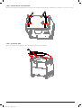
Step 7 Fit the Fat Tray.
Make sure the drain hole in the fat tray lines up with the drain hole in the top
panel.
Step 8 Attach the Doors.
a) Attach door hinges (22) to the cabinet left (7) & right (8) side panels top and
bottom, each hinge with four M4*10mm screws (C).
b) Attach the doors (11) to the hinges with two M4*10mm screws (C) on each
hinge.

10
546565.A.3 - May 2019
STEP 8. ATTACH THE DOORS.
a) Attach door hinges (22) to the cabinet left (7) and right (8) side panels top and bottom, each hinge with four M4*10mm screws (C).
b) Atttach the doors (11) to the hinges with two M4*10mm screws (C) on each hinge.
Step 7 Fit the Fat Tray.
Make sure the drain hole in the fat tray lines up with the drain hole in the top
panel.
Step 8 Attach the Doors.
a) Attach door hinges (22) to the cabinet left (7) & right (8) side panels top and
bottom, each hinge with four M4*10mm screws (C).
b) Attach the doors (11) to the hinges with two M4*10mm screws (C) on each
hinge.
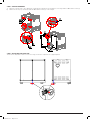
STEP 9. ADJUSTING THE DOOR GAP.
There are two adjustable screws on each door hinge, use them to adjust the door gap if required

11
546565.A.3 - May 2019
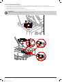
STEP 10. ATTACH THE FIREBOX. (USE TWO PEOPLE FOR THIS STEP)
a) Place the firebox and hood assembly (1) onto the cabinet, then carefully open the hood while holding the assembly steady.
b) Fix the firebox onto the cabinet from inside the firebox with four M6 washers (F) and M6*12mm screws (B).
c) Fully tighten all screws.
Step 9 Adjusting the Door Gap.
There are 2 adjustable screws on each door hinge, use them to adjust the door
gap if required.
Note: It is better to wait until the unit is fully assembled and in position before
finally adjusting the doors.
Step 10 Attach the Firebox. (Use two people for this step)
a) Place the firebox and hood assembly (1) onto the cabinet, then carefully
open the hood while holding the assembly steady.
b) Fix the firebox onto the cabinet from inside the firebox with four M6 washers
(F) and M6*12mm screws (B).
Fully tighten all screws.
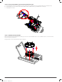
STEP 11. REMOVE THE SIDE BURNER.
Remove the trivet from the side burner assembly (2), then remove the three M4*10mm screws and fiber washers on the side shelf to
release the spill tray and burner.
Keep the trivet, screws and side burner aside for Step 16.
Step 11 Remove the Side Burner.
Remove the trivet from the side burner assembly (2), then remove the three
M4*10mm screws and fiber washers on the side shelf to release the spill tray
and burner.
Keep the trivet, screws and burner aside for STEP 16.
Step 12 Attach the Side Burner Control Panel and Side Shelf Front Panel
a) Attach the side burner control panel (3) to the side burner shelf (2) with four
M4*8mm screws (G).
b) Attach the right side shelf front panel (5) to the right side shelf (4) with four
M4*8mm screws (G).

12
546565.A.3 - May 2019
STEP 12. ATTACH THE SIDE BURNER CONTROL PANEL AND SIDE SHELF FRONT PANEL.
a) Attach the side burner control panel (3) to the side burner shelf (2) with four M4*8mm screws (G).
b) Attach the right side shelf front panel (5) to the right side shelf (4) with four M4*8mm screws (G).
Step 11 Remove the Side Burner.
Remove the trivet from the side burner assembly (2), then remove the three
M4*10mm screws and fiber washers on the side shelf to release the spill tray
and burner.
Keep the trivet, screws and burner aside for STEP 16.
Step 12 Attach the Side Burner Control Panel and Side Shelf Front Panel
a) Attach the side burner control panel (3) to the side burner shelf (2) with four
M4*8mm screws (G).
b) Attach the right side shelf front panel (5) to the right side shelf (4) with four
M4*8mm screws (G).
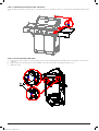
STEP 13. PREPARATION TO ATTACH SIDE BURNER SHELF.
Partially screw two M6*12mm screws (B) into the upper holdes on the left side panel of the firebox, leave the screw heads protruding
approximately five mm out.

13
546565.A.3 - May 2019
STEP 14. ATTACH THE SIDE BURNER SHELF.
a) Hang the side burner assembly onto the protruding screws, insert and partially tighten three M6*12mm screws (B) into the lower holes
as shown.
b) Align the side burner control panel to the main BBQ control panel, then tighten the upper protruding screws.
c) Fully tighten all screws.
Step 13 Preparation to Attach Side Burner Shelf.
Partially screw two M6*12mm screws (B) into the upper holes on the left side
panel of the firebox, leave the screw heads protruding approximately five mm
out.
Step 14 Attach the Side Burner Shelf.
a) Hang the side burner assembly onto the protruding screws, insert and
partially tighten three M6*12mm screws (B) into the lower holes as shown.
b) Align the side burner control panel to the main bbq control panel, then
tighten the upper protruding screws.
c) Fully tighten all screws.
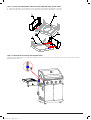
STEP 15. ATTACH THE SIDE BURNER VALVE AND KNOB.
a) Insert the side burner valve stem from behind the control panel, through the knob bezel, fix the valve with two M4*8mm screws (G).
b) Tighten firmly.
c) Insert the knob (12) onto the valve stem as shown.
WARNING!
DO NOT disconnect the gas hose from the side burner valve. Take care not to twist or kink the gas hose.
Step 15 Attach the Side Burner Valve and Knob.
a) Insert the side burner valve stem from behind the control panel, through the
knob bezel, fix the valve with two M4*8mm screws (G).
Tighten firmly.
b) Insert the knob (12) onto the valve stem as shown.
DONOT disconnect the gas hose from the side burner valve. Take care not to
twist or kink the gas hose.
Step 16 Attach the side burner.
a)
Fit the spill tray and side burner through the shelf and engage the side
burner tube onto the valve nozzle as shown.
b)
Fix the spill tray and side burner firmly in place with three M4*10mm screws
and fibre washers as shown. Make sure the side burner tube is properly
engaged onto the valve nozzle.
c)
Fit the ignition wire onto the bottom of the ignition pin.
d)
Fit the side burner trivet into the three holes in the side burner shelf as
shown.
ENSURE the burner tube is engaged onto the valve nozzle as shown.

14
546565.A.3 - May 2019
STEP 16. ATTACH THE SIDE BURNER.
a) Fit the spill tray and side burner through the shelf and engage the side burner tube onto the valve nozzle as shown.
b) Fix the spill tray and side burner firmly in place with three M4*10mm screws and fibre washers as shown. Make sure the side burner
tube is properly engaged onto the valve nozzle.
c) Fit the ignition wire onto the bottom of the ignition pin.
d) Fit the side burner trivet into the three holes in the side burner shelf as shown.
IMPORTANT
ENSURE the burner tube is engaged onto the valve nozzle as shown.

15
546565.A.3 - May 2019
STEP 17. PREPARATION TO ATTACH RIGHT SIDE SHELF.
Screw two M6*12mm (B) into the upper holes on the right side panel of the firebox, leave the screw heads protruding approximately 5mm
out.
5
m
m
STEP 18. ATTACH THE RIGHT SIDE SHELF.
a) Hang the side shelf assembly onto the protruding screws, insert and partially tighten three M6*12mm screws (B) into the lower holes
as shown.
b) Align the right side shelf front panel to the main BBQ control panel, then tighten the upper protruding screws.
c) Tighten all screws.
Step 17 Preparation to Attach Right Side Shelf.
Screw two M6*12mm screws (B) into the upper holes on right side panel of
firebox, leave the screw heads protruding approximately 5mm out.
Step 18 Attach the Right Side Shelf.
a) Hang the side shelf assembly onto the protruding screws, insert and partially
tighten three M6*12mm screws (B) into the lower holes as shown.
b) Align the right side shelf front panel to the main bbq control panel, then
tighten the upper protruding screws.
Tighten all screws.

16
546565.A.3 - May 2019
STEP 19. FIT THE GREASE CUP AND FOIL CUP.
IMPORTANT
Put the foil cup (26) into the grease cup (25), then slide the grease cup into the grease cup bracket.
Step 19 Fit the Grease Cup and Foil Cup
Put the grease cup foil cup (26) into the grease cup (25), then slide the grease
cup into the grease cup bracket.
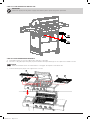
STEP 20. PLACE THE BARBEQUE INTERNALS.
a) Fit the flame tamers (17) onto the support tabs, under the cooking grill.
b) Place the cooking grill (19) and hot plate (20) into the firebox with square draining hole of hot plate to the middle as shown.
NOTE:
Make sure the flame tamers are underneath the cooking grill. The hotplate can be either side.
c) Instal the warming rack (18) into four support holes as shown.
STEP 20: Place the Barbeque Internals.
a) Fit the flame tamers (17) onto the support tabs, under the cooking grill.
b) Place the cooking grill (19) and hot plate (20) into the firebox with square draining
hole of hot plate to the middle as shown.
Note: Make sure the flame tamers are underneath the cooking grill. The hotplate can
be either side.
c) Install the warming rack (18) into four support holes as shown.

17
546565.A.3 - May 2019
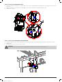
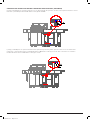
CONFIGURE THE ALFRESCO ISLAND WITH SEPARATELY AVAILABLE UNITS (CONTINUED)
If joining your barbeque to an optional sink unit or to an optional range unit, open the cart door for that optional unit, then connect
that unit to your barbeque with four M6*16mm screws (A) AS SHOWN.
f joining your barbeque to an optional sink unit and an optional rnage unit all together, open the cart doors for the sink and the
range units, connect the first unit to your barbeque with four M6*16mm screws (A) as shown, then connect the second unit to
the first unit with another four M6*16mm screws (A) as shown.

18
546565.A.3 - May 2019
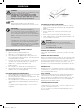
OPTIONAL ROTISSERIE - ASSEMBLY
INSTRUCTIONS
TOOLS NEEDED FOR ASSEMBLY
Crosshead screwdriver, 10mm A/F spanner, 2x 8mm A/F Spanners.
Assemble the Prong (24), the Rod (25) and the Guide (27), the
Rotisserie handle (28) together as in the diagram.
NOTE:
Rotisserie Rod 25 is threaded LH, assemble by turning
rod anti-clockwise. Tighten with 8mm A/F Spanners.
This connection must remain spanner tight.
Place inside of grill
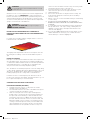
Assemble the Motor holder (29) to the appliance with 2pcs Screw
M6*10 (a), 2 fibre washer (c) and 2pcs Nut M6 (f) as the
diagram. Place the battery (31) into the Motor (30). Assemble the
Motor and Rotisserie to the appliance as the picture.
NOTE:
Take note of the battery + - positions prior to fitting the
batteries.
NOTE:
There is an option to use a mains adaptor (not stocked).
Requires:
Mains adaptor 240 volt > 3 volt DC 3 milliamps or
greater.
LEAK TESTING
WHEN TO TEST:
The BBQ gas bottle, regulator & hose assembly should be checked
for leaks, using the soapy water leak test, every time you reconnect
your regulator to the BBQ gas bottle. You should also test after any
long period of non-use, such as at the beginning of BBQ season.
WHAT TO USE:
You will need a soapy water solution to check for any leaks. Mixing
liquid hand soap with water will work fine (do not use any other
household cleaning products).
HOW TO TEST:
Put some soapy water in a spray bottle or a dish. Turn on the gas
bottle but do not turn on the BBQ. Next, spray the entire valve,
regulator and hose assembly with the soapy water including where
the hose connects to the BBQ. Alternatively, you can apply the
soapy water with a paint brush, basting brush.
Bubbles will form if there is a gas leak and you may also smell the
gas. If you find a leak, turn off the gas bottle immediately!
Do not turn back on or attempt to use the BBQ if a gas leak has
been detected, contact your local BBQ Dealer for repair.
INSTALLATION
This barbecue is for outdoor use only and should be placed in
a well-ventilated area. Take care to ensure that the minimum
clearances guidelines are followed:
Minimum clearances:
From sides: 430mm; From back: 430mm
From above (vertical): 1000mm
Keep this barbecue away from any flammable materials! This
appliance shall only be used in an above ground open-air situation
with natural ventilation, without stagnant areas, where gas leakage
and products of combustion are rapidly dispersed by wind and
natural convection. This barbecue is not designed for marine use.
Any enclosure in which the appliance is used shall comply with one
of the following:
1. An enclosure with walls on all sides, but at least one permanent
opening at ground level and no overhead cover.
2. Within a partial enclosure that includes an overhead cover and
no more than two walls.
3. Within a partial enclosure that includes an overhead cover and
more than two walls, the following shall apply:
a. at least 25% of the total wall area is completely open and
unrestricted.
b. at least 30% of the remaining wall area is open and
unrestricted

19
546565.A.3 - May 2019
4. In the case of balconies, at least 20% of the total of the side,
back and front wall areas shall be and remain open and
unrestricted.
See following diagrams for further illustration:
FIGURE F1-OUTDOOR AREA-EXAMPLE 1
FIGURE F2-OUTDOOR AREA-EXAMPLE 2
Both ends open
FIGURE F5-OUTDOOR AREA-EXAMPLE 5
FIGURE F3-OUTDOOR AREA-EXAMPLE 3
FIGURE F4-OUTDOOR AREA-EXAMPLE 4
Open side at
least 25% of total
wall area
30 percent or more in total
of the remaining wall area is
open and unrestricted
Open side at
least 25% of total
wall area
30 percent or more in total
of the remaining wall area is
open and unrestricted
OTHER PRECAUTIONS
Do not obstruct any of the ventilation openings in the barbecue
body. Also, position the gas supply cylinder inside the cabinet, in
the cylinder base positioning hole. Should you need to change
the gas cylinder, confirm that the cylinder is off, and that there are
no sources of ignition (cigarettes, open flame, sparks, etc.) near
before proceeding. Be sure to inspect the gas hose and ensure it
is free of any twisting or tension. The hose should hang freely with
no bends, folds, or kinks, which could obstruct free flow of gas.
Apart from the connection point, no part of the hose should touch
any hot barbecue parts. Inspect the hose before use. If the hose
is damaged, it must be replaced with a hose suitable for use with
ULPG and meet the national standards for the country of use. The
length shall not exceed 1.5m. Should minimum clearances not
be adhered to severe flare up may be experienced due to lack of
airflow around the barbecue, thus voiding manufacturer’s warranty.
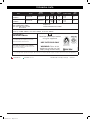
GAS AND REGULATOR INFORMATION
This barbecue is designed for LP gas use only. Bottle sizes of 4.5kg
or greater are recommended for use with this barbecue. Suitable
LPG regulators must have an outlet pressure of 2.75 kPa. You must
have the proper regulator and bottle in order for the barbecue to
operate safely and efficiently. Please consult your local gas dealer
for the most suitable gas cylinders. Please note the regulator
supplied with this barbecue is of an approved type. The manifold
thread type is 5/8” x 18.
For more information on pipe sizing, please refer to AS/NZS 5601 /
AG601 for details.
The gas cylinder must always be stored or used in an upright
position.
Gas Cylinder
Bleeder Valve Screw
Gas Shutoff Valve
Tighten in this direction
POL regulator
and hose
Protector Cap
FIXING THE GAS REGULATOR TO THE CYLINDER
Confirm all barbecue control knobs are in the off position. Hand-
tighten the regulator supplied with this barbecue to the gas cylinder
by screwing in an anti-clockwise direction.
DO NOT OVERTIGHTEN!
As the regulator is fitted with a soft nose, it should only be tightened
a further 1/4 turn after resistance is first felt.

20
546565.A.3 - May 2019
OPERATION
WARNING!
Before proceeding, be certain you understand the safety
information contained in this manual.
This barbecue is not designed to be used with
more than 66% of the cooking area as a solid
plate. Full coverage of plates will cause excessive
build-up of heat and damage the barbecue.
NOTE:
Before using the barbecue for the first time, the
barbecue must be lit and burning for 30 minutes on the
“low” setting.
IMPORTANT
The The regulator supplied with this BBQ may
incorporate an Excess Flow Control Safety Device. The
Excess Flow Control will activate to prevent gas flow
should a regulator malfunction occur. It is important that
the BBQ operator understands that all gas valves on the
BBQ are closed in the OFF position prior to opening the
gas cylinder valve.
If the BBQ valves are open prior to opening the cylinder
valve, the Excess Flow Control will be activated and
prevent the BBQ from being lit. To reset, close the BBQ
valves and gas cylinder valve, wait for 1 minute and use
correct lighting procedure as detailed below.
MAIN BURNER AND SIDE BURNER LIGHTING
(INTEGRATED IGNITION)
1. Open the lid before igniting the barbecue
2. Check all the knobs are in the “OFF” position
3. Open the gas control valve at the gas cylinder
4. The valves fitted to this BBQ include a safety feature. The
valve must be depressed before turning. This feature prevents
accidental activation of the knob
5. From the “OFF” position, push in then turn control knob anti-
clockwise to the “HI” position until hear a “click” sound
6. Repeat step 4, 3-4 times until the burner is lit
7. If the burner fails to light, turn off and wait for 5 minutes, then
begin from step 4
8. Once a burner is lit, similarly light the remaining burners.
9. Turn the knob anticlockwise to adjust the heat from High –
medium – Low to your heat requirement.
FOR MANUAL IGNITION (MAIN BURNER)
1. Light a 90mm barbecue match and hold adjacent to the lighter
hole at the right end of the barbecue. (Fig.1)
2. Turn the right hand gas control knob to the high position. The
burner will light from the match.
3. Once the right burner is lit, the burner next to it can be turned
on and will light off the lit burner. Repeat until all burners are
alight.
4. Each burner can be adjusted. Turn the knob anticlockwise
to adjust the heat from High - medium - Low to your heat
requirement.
MANUAL IGNITION:
Light here with a
90mm match or
lighting gun
FOR MANUAL LIGHTING (SIDE BURNER)
1. Turn all knobs to “OFF” then open the LP tank valve. Always
keep your face and body as far from the grill as possible when
lighting.
2. Raise side burner lid.
3. Push in and then turn control knob anticlockwise to high
position.
4. Place a lit match near the burner until the burner ignites.
5. If burner fails to light, turn off and wait 5 minutes, then try
6. again. If burner still does not light after repeated attempts, call
7. your local dealer for assistance.
WARNING!
Caution/Danger: Extreme care is required when
cooking with hood in closed position. Frequent checks
must be undertaken for the heat and temperature to
ensure safe cooking.
Too much heat can cause fire.
TURNING OFF A BURNER
Push in then turn each burner control knob clockwise to the “OFF”
position.
TURNING OFF YOUR BARBECUE
When you have finished using your barbecue, turn off the gas at the
bottle. Push in and then turn all the control valves fully clockwise to
the “OFF” position. Wait until the barbecue is sufficiently cool before
replacing the barbecue lid or closing its hood. Once cooled, a
protective cover should always be fitted to the barbecue to protect
your investment from the ailments when not in use.
WARMING RACK
Warming racks are a convenient way to keep cooked food warm or
to warm items such as bread rolls. Always check that your warming
rack is properly fitted before use.
GRILL COOKING
The burners heat up the flame tamers underneath the grill, which
in turn heats the food on the grill. The natural juices produced
during cooking fall onto the flame tamers below and vaporise. The
subsequent rising smoke bastes the food, as it travels upwards,
imparting that unique barbecue flavour.
COOKING AND USE OF HOOD
Barbecues equipped with a roasting hood give the option of
cooking with hood closed to form an ‘oven’ for roasting food, such
as joints of meat, whole chickens, etc.
Do not cook with the hood down at a high temperature for long
periods of time.
Page is loading ...
Page is loading ...
Page is loading ...
Page is loading ...
Page is loading ...
Page is loading ...
Page is loading ...
Page is loading ...
-
 1
1
-
 2
2
-
 3
3
-
 4
4
-
 5
5
-
 6
6
-
 7
7
-
 8
8
-
 9
9
-
 10
10
-
 11
11
-
 12
12
-
 13
13
-
 14
14
-
 15
15
-
 16
16
-
 17
17
-
 18
18
-
 19
19
-
 20
20
-
 21
21
-
 22
22
-
 23
23
-
 24
24
-
 25
25
-
 26
26
-
 27
27
-
 28
28


Masport Tasman Series Owner's manual
- Category
- Barbecues & grills
- Type
- Owner's manual
- This manual is also suitable for
Ask a question and I''ll find the answer in the document
Finding information in a document is now easier with AI
Related papers
-
Masport VACATIONER 6 S2 Owner's manual
-
-
-
-
-
Masport Maestro Owner's manual
-
-
 Regency Fireplace Products Masport G51-NG Operating instructions
-
-
 Country Hearth Woodfires Series Operating instructions


Other documents
-
Home Decorators Collection 9390600210 Installation guide
-
Kmart 42688679 User manual
-
-
Gasmate BQ1077 User manual
-
-
Char-Broil Patio Bistro 15601632 User manual
-
-
IKEA 594.003.98 User manual
-
 gascraft BG126N3B Toulon Assembly & Operating Instructions
-
 Jumbuck HS-UM006AS Assembly & Operation Instructions

