Page is loading ...

Operator’s Manual
Micro 19
Serial #16900000 - Up
94553r1
September 2017
Specifications . . . . . . . . . . . . . . . . . . . . . . . . . . . . . . . . . . . . . . . . . . . . inside cover
Introduction . . . . . . . . . . . . . . . . . . . . . . . . . . . . . . . . . . . . . . . . . . . . . . . . . . . . . . . 1
Safety. . . . . . . . . . . . . . . . . . . . . . . . . . . . . . . . . . . . . . . . . . . . . . . . . . . . . . . . . . . . . . 2
Safety Alert Symbols . . . . . . . . . . . . . . . . . . . . . . . . . . . . . . . . . . . . . . . . . . . . . . . . . . 2
Fall Protection . . . . . . . . . . . . . . . . . . . . . . . . . . . . . . . . . . . . . . . . . . . . . . . . . . . . . . . . 3
Electrocution Hazard. . . . . . . . . . . . . . . . . . . . . . . . . . . . . . . . . . . . . . . . . . . . . . . . . . 3
Tip-over Hazards. . . . . . . . . . . . . . . . . . . . . . . . . . . . . . . . . . . . . . . . . . . . . . . . . . . . . . 4
Fall Hazards. . . . . . . . . . . . . . . . . . . . . . . . . . . . . . . . . . . . . . . . . . . . . . . . . . . . . . . . . . . 5
Collision Hazards . . . . . . . . . . . . . . . . . . . . . . . . . . . . . . . . . . . . . . . . . . . . . . . . . . . . . 5
Additional Safety Hazards . . . . . . . . . . . . . . . . . . . . . . . . . . . . . . . . . . . . . . . . . . . . . 6
Battery Safety. . . . . . . . . . . . . . . . . . . . . . . . . . . . . . . . . . . . . . . . . . . . . . . . . . . . . . . . . 6
Controls & Components . . . . . . . . . . . . . . . . . . . . . . . . . . . . . . . . . . . . . . . . . . . . . 7
Component Locations . . . . . . . . . . . . . . . . . . . . . . . . . . . . . . . . . . . . . . . . . . . . . . . . 7
Platform Controls . . . . . . . . . . . . . . . . . . . . . . . . . . . . . . . . . . . . . . . . . . . . . . . . . . . . . 8
Lower Controls . . . . . . . . . . . . . . . . . . . . . . . . . . . . . . . . . . . . . . . . . . . . . . . . . . . . . . . 9
Workplace Inspection . . . . . . . . . . . . . . . . . . . . . . . . . . . . . . . . . . . . . . . . . . . . . . 10
Operating Instructions & Functions Test. . . . . . . . . . . . . . . . . . . . . . . . . . . . . 10
Prestart . . . . . . . . . . . . . . . . . . . . . . . . . . . . . . . . . . . . . . . . . . . . . . . . . . . . . . . . . . . . . . 11
Functions Test . . . . . . . . . . . . . . . . . . . . . . . . . . . . . . . . . . . . . . . . . . . . . . . . . . . . . . . 11
Operating Instructions . . . . . . . . . . . . . . . . . . . . . . . . . . . . . . . . . . . . . . . . . . . . . . . 14
Shutdown Procedure . . . . . . . . . . . . . . . . . . . . . . . . . . . . . . . . . . . . . . . . . . . . . . . . 19
Battery Charging . . . . . . . . . . . . . . . . . . . . . . . . . . . . . . . . . . . . . . . . . . . . . . . . . . 19
Maintenance . . . . . . . . . . . . . . . . . . . . . . . . . . . . . . . . . . . . . . . . . . . . . . . . . . . . . . 20
Routine Maintenance . . . . . . . . . . . . . . . . . . . . . . . . . . . . . . . . . . . . . . . . . . . . . . . . 21
Frequent and Annual Maintenance . . . . . . . . . . . . . . . . . . . . . . . . . . . . . . . . . . . 21
Lubrication . . . . . . . . . . . . . . . . . . . . . . . . . . . . . . . . . . . . . . . . . . . . . . . . . . . . . . . . . . 22
Pre-Start Inspection Checklist . . . . . . . . . . . . . . . . . . . . . . . . . . . . . . . . . . . . . . . . 23
Frequent Inspection Checklist . . . . . . . . . . . . . . . . . . . . . . . . . . . . . . . . . . . . . . . . 24
Annual Inspection Report . . . . . . . . . . . . . . . . . . . . . . . . . . . . . . . . . . . . . . . . . . . . 25
Warning and Instructional Decals. . . . . . . . . . . . . . . . . . . . . . . . . . . . . . . . . . . 26
Troubleshooting . . . . . . . . . . . . . . . . . . . . . . . . . . . . . . . . . . . . . . . . . . . . . . . . . . 30
Transport and Lifting Instructions . . . . . . . . . . . . . . . . . . . . . . . . . . . . . . . . . . 30
Loading . . . . . . . . . . . . . . . . . . . . . . . . . . . . . . . . . . . . . . . . . . . . . . . . . . . . . . . . . . . . . 30
Lifting Instructions . . . . . . . . . . . . . . . . . . . . . . . . . . . . . . . . . . . . . . . . . . . . . . . . . . . 32

—Specifications—
Micro 19
Working Height*
24.6 ft 7.5 m
Platform Height
18 ft 5.5 m
Maximum Drive Height
18 ft 5.5 m
79 in. 2.0 m
Stowed Height
39 in. 1.0 m
Platform Extension Length
23.6 in. 0.6 m
Machine Weight** (Unloaded)
2690 lb 1220 kg
Lift Capacity Total
500 lb 227 kg
Deck Extension Capacity
1 Person / 220lb (100 kg)
Maximum Occupants 2
Platform Length (Extended)
78 in. 2 m
Platform Length (Retracted)
54 in. 1.4 m
Width (Overall)
32 in. 0.81 m
Platform Dimensions (length x width)
53.9 x 27.6 in 1.37 x 0.7m
Wheel Base
44.5 in 1.13 m
Turning Radius--Inside
17.7 in. 0.45m
Ground Clearance--Stowed
2.4 in
6 cm
Ground Clearance--Elevated 0.6 in 1.5 cm
Drive Speed (Proportional) Stowed 0-2.5 mph 0-4 km/h
Raised or extended
0-.5 mph 0-8 km/h
Gradability 25%/14°
Maximum Side Slope--Stowed 5°
Ground Pressure/Wheel
116 psi
8.2 kg/cm
2
Maximum Wheel Load 960 lb 435 kg
Occupied Floor Pressure
242 psf
1177 kg/m
2
Maximum Operating Wind Speed 28 mph / 12.5 m/sec (45 km/h)
Tire Size
9 x 4 inch/230 x 100mm
Lug Nut Torque 19 ft-lb / 25.5 Nm
Secured with cotter pin
Hydraulic Pressure
2320 psi/ 160 bar
Power System Voltage 24 Volt DC
Battery Charger Input 110-230 V AC, 50-60 Hz
Output 24 Volt DC
Batteries
Two 12 Volt Deep Cycle 115Ah
Meets applicable requirements of ANSI A92.6-2006.
*Working Height adds 6 feet (2 m) to platform height. **Weight may increase with certain options.
Airborne Noise Emissions
<70 dB
Top Guardrail
Platform Floor

94553r1
Micro 19
Page 1
September 2017
Micro 19
Introduction
Introduction
This Operator’s Manual has been designed to provide you, the owner, user or operator, with the instructions and operating procedures
essential to properly and safely operate your MEC Aerial Work Platform for positioning personnel, along with their necessary tools
and materials, to overhead work locations.
The Operator’s Manual must be read and understood prior to operating your MEC Aerial Work
Platform. The user/operator should not accept operating responsibility until he/she has read and
understands the operator’s manual as well as having operated the MEC Aerial Work Platform under
supervision of an authorized, trained and qualified operator.
It is essential that the operator of the aerial work platform is not alone on the workplace during
operation.
Modifications of this machine from the original design and specifications without written permission
from MEC are strictly forbidden. A modification may compromise the safety of the machine, subjecting
operator(s) to serious injury or death.
Your MEC Aerial Work Platform has been designed, built, and tested to provide safe,
dependable service. Only authorized, trained and qualified personnel shall be allowed to
operate or service the machine.
MEC, as manufacturer, has no direct control over machine application and operation. Proper
safety practices are the responsibility of the owner, user and operator.
If there is a question on application and/or operation contact:
MEC Aerial Platform Sales Corp.
1401 South Madera Ave • Kerman, CA 93630 USA
Ph: 1-877-635-5438 • 559-842-1500 • Fax: 559-842-1522
www.mecawp.com

94553r1 Page 2
September 2017
Micro 19
Micro 19
Safety
Safety
DO NOT operate this machine until you have read and understood this manual, have performed the Workplace Inspection,
Pre-Start Inspection and Routine Maintenance, and have completed all the test operations detailed in the Operating
Instructions section.
Failure to read, understand and follow all safety rules, warnings, and instructions could result in serious injury or death. For your
safety and the safety of those around you, you must operate your machine as instructed in this manual.
MEC designs aerial work platforms to safely and reliably position personnel, along with their necessary tools and materials, at
overhead work locations. The owner/user/operator of the machine should not accept responsibility for the operation of the machine
unless properly trained.
ANSI and other applicable standards identify requirements of all parties who may be involved with self-propelled elevating work
platforms. The ANSI/SIA A92.6-2006 Manual of Responsibilities is considered a part of this machine and can be found in the manual
compartment, located at the platform control station. To ensure safe use of machine, inspections and training specified in ANSI/SIA
A92.6-2006 must be performed at designated intervals as prescribed.
California Proposition 65 Warning
This product contains chemicals known to the State of California to cause cancer and/or birth
defects or other reproductive harm.
Safety Alert Symbols
MEC manuals and decals use symbols and colors to help you recognize important safety, operation and maintenance information.
RED – Indicates an imminently hazardous situation which, if not avoided, will result in death or serious
injury.
ORANGE – Indicates a potentially hazardous situation which, if not avoided, could result in death or
serious injury.
YELLOW with alert symbol – Indicates a potentially hazardous situation which, if not avoided, may
result in minor or moderate injury.
YELLOW without alert symbol – Indicates a potentially hazardous situation which, if not avoided, may
result in property damage.
GREEN – Indicates operation or maintenance information.

94553r1
Micro 19
Page 3
September 2017
Safety
Micro 19
Fall Protection
Operators must comply with employer, job site and governmental rules regarding the use of
personal protective equipment.
If required by your employer or job site, use personal fall protection equipment (PFPE) when
operating this machine.
All PFPE must comply with applicable governmental regulations, and must be inspected and
used in accordance with the PFPE manufacturer’s instructions.
Fall restraint must be properly attached to a designated anchorage point when driving or
operating the machine. Attach only one fall restraint to each anchorage point.
Electrocution Hazard
ELECTROCUTION HAZARD! THIS MACHINE IS NOT INSULATED!
DEATH OR SERIOUS INJURY will result from contact with or inadequate clearance from any electrically
charged conductor.
You must maintain a CLEARANCE OF AT LEAST 10 FEET (3.05 m) between any part of the machine, or its
load, and any electrical line or apparatus carrying over 300 Volts up to 50,000 Volts. One foot (30.5 cm)
additional clearance is required for every additional 30,000 Volts.
Observe Minimum Safe Approach Distance.
This machine is not electrically insulated and will not provide protection from contact with or
proximity to electrical current.
Maintain safe distances from electrical power lines and apparatus in accordance with
applicable government regulations and the following chart:
Allow for platform movement, electrical line sway or sag and beware of strong or gusty winds.
Keep away from the machine if it contacts energized power lines. Personnel on the ground or
in the platform must not touch or operate the machine until energized power lines are shut off.
Do not use the machine as a ground for welding.
Art_4292
Art_2824
Art_2823
Minimum Save Approach Distance
Voltage Minimum Safe Approach Distance
Phase to Phase Feet Meters
0 to 300 Volts Avoid Contact
Over 300V to 50kv 10 3.1
Over 50KV to 200KV 15 4.6
Over 200KV to 350KV 20 6.1
Over 350KV to 500KV 25 7.6
Over 500KV to 750KV 35 10.7
Over 750KV to 1000KV 45 13.7

94553r1 Page 4
September 2017
Micro 19
Safety
Micro 19
Tip-over Hazards
DO NOT exceed the maximum platform capacity. The weight of options and accessories will
reduce the rated platform capacity and must be factored into the total platform load. Refer to
the decals on the options.
DO NOT elevate the platform when the machine is on a surface that is soft and/or on a slope.
DO NOT depend on the tilt alarm as a level indicator. STOP if the tilt alarm sounds and the
red light illuminates when the platform is raised. Use extreme caution to lower the platform.
Move the machine to a firm, level surface.
Driving: DO NOT drive the machine on a slope that exceeds the maximum uphill, downhill
or side slope rating. Slope rating applies to machines in the stowed position.
Driving in stowed position: use extreme care and reduce speed when driving across uneven
terrain, debris, unstable or slippery surfaces, and near holes or drop-offs.
Driving with the platform elevated: DO NOT drive on or near uneven terrain, unstable
surfaces, curbs, drop-offs or other hazardous conditions. DO NOT drive the machine faster
than .7 mph/1.1 km/h while elevated
DO NOT push off or pull toward any object outside the platform. DO NOT push the machine
or other objects with the platform. DO NOT contact adjacent structures with the platform.
DO NOT tie the platform to adjacent structures.
DO NOT use the platform controls to free a platform that is caught, snagged or otherwise
prevented from normal motion by an adjacent structure.
DO NOT elevate the platform when wind speeds are in excess of 28 m.p.h. (12.5 m/s). If wind
speeds exceed 28 m.p.h. (12.5 m/s) when the platform is elevated, carefully lower the platform
and discontinue operation.
DO NOT increase the surface area of the platform (i.e. cover the rails with tarp or plywood).
Increased surface area exposed to the wind will decrease machine stability.
DO NOT attach overhanging loads or use the machine as a crane. DO NOT place loads outside
the platform perimeter.
NEVER transport tools and materials unless they are firmly secured. Secure all tools and loose
materials.
NEVER alter or disable any machine components.
NEVER replace any part of the machine with items of different weight or specification.
NEVER modify or alter the work platform without written permission from MEC.
NEVER place ladders or scaffolds in the platform or against any part of the machine.
NEVER use the machine on a moving or mobile surface or vehicle.
Ensure that all tires are in good condition and lug nuts are properly torqued.
DO NOT operate the machine with the chassis trays open.
DO NOT alter or disable the limit switches or machine components that in any way affect
safety and stability.
DO NOT replace items critical to machine stability with items of different weight or
specification. DO NOT modify or alter this machine without prior written permission from
the manufacturer.
DO NOT use batteries that weigh less than the original equipment. Each battery must weigh
55 lbs/25 kg. The batteries must weigh a minimum of 110 Ibs/50 kg.
DO NOT OVERLOAD
DO NOT DRIVE ON IRREGULAR OR
UNSTABLE SURFACE
DO NOT PUSH OR PULL OBJECTS
OUTSIDE PLATFORM
DO NOT ELEVATE IN WINDY
CONDITIONS
DO NOT USE AS CRANE
Art_2828
Art_2834
Art_2833
Art_2831
Art_2832
Maximum Allowable Side Force
50 lbs (222 N) per person

94553r1
Micro 19
Page 5
September 2017
Safety
Micro 19
Fall Hazards
DO NOT sit, stand or climb on the platform guard rails. Maintain a firm footing on the
platform floor at all times.
DO NOT exit the platform when elevated. DO NOT climb down from the platform when
elevated.
Keep the platform floor clear of debris.
DO NOT fasten a fall restraint lanyard to an adjacent structure.
Ensure that the platform entry is properly closed and secured before operating the machine.
Ensure that the guard rails are properly installed and in good condition before operating the
machine.
Operators must comply with employer and job site rules and governmental regulations
regarding the use of personal protective equipment.
Collision Hazards
Check path before moving for equipment, materials or other obstructions.
Check path before moving for overhead obstructions.
Check path before moving for crushing hazards when holding the platform rail.
Be aware of limited sight distance and blind spots when driving or operating.
Be aware of extended platform position(s) when moving the machine.
Observe and use color-coded direction arrows on the platform controls and platform decal
plate for drive and steer functions.
Reduce travel speed when moving the machine on slopes, when near personnel and obstacles,
or when surface conditions are wet, slippery or otherwise limiting.
DO NOT operate in the path of any crane unless the controls of the crane have been locked out
and/or precautions have been taken to prevent any possible collision.
Stunt driving and horseplay are PROHIBITED.
Watch for personnel and obstructions below the platform when lowering the platform.
Keep hands and limbs out of scissors.
Use common sense and planning when operating the machine with the controller from the
ground. Maintain safe distances between the operator, the machine and fixed objects.
DO NOT EXIT PLATFORM WHEN
ELEVATED
DO NOT CLIMB ON RAILS
Art_2826
Art_2825
Art_2835
Art_2829
Art_2827

94553r1 Page 6
September 2017
Micro 19
Safety
Micro 19
Additional Safety Hazards
Explosion and Fire Hazards
DO NOT operate the machine in hazardous locations or locations where potentially flammable
or explosive gasses or particles may be present.
Damaged Machine Hazards
Conduct a thorough pre-start inspection of the machine and test all functions before each work
shift to check for damage, malfunction and unauthorized modification. Tag and remove a
damaged, malfunctioning or modified machine from service. DO NOT use a damaged,
malfunctioning or modified machine.
Routine maintenance must be performed by the operator before each work shift. Scheduled
maintenance must be performed by a qualified service technician at scheduled intervals. Tag
and remove from service any machine that has not had scheduled preventative maintenance
performed.
Check that all safety and instructional decals are in place and undamaged.
Check that the operator’s, safety and responsibilities manuals are present in the storage
container located in the platform. All manuals must be complete, undamaged and readable.
Bodily Injury Hazards
DO NOT operate the machine when there is a hydraulic fluid or air leak. Hydraulic fluid or air
under pressure can penetrate and/or burn skin.
All compartments must remain closed and secure during machine operation. Improper
contact with components under any cover will cause serious injury. Only trained maintenance
personnel should access compartments. The operator should only access a compartment when
performing pre-operation inspection.
Weld Line to Platform Safety (if equipped)
Read, understand and follow all warnings and instructions provided with the welding power
unit.
Do not connect weld leads or cables unless the welding power unit is turned off at the platform
controls.
DO NOT operate unless the weld cables are properly connected.
DO NOT connect the ground lead to the platform.
Battery Safety
Burn Hazards
Batteries contain acid. Always wear protective clothing and eye wear when working with
batteries.
Avoid spilling or contacting battery acid. Neutralize battery acid spills with baking soda and
water.
Explosion Hazard
Keep sparks, flame and lighted tobacco away from batteries. Batteries emit explosive gas. The
battery tray should remain open during the entire charging cycle.
Electrocution Hazard
Avoid contact with electrical terminals.

94553r1
Micro 19
Page 7
September 2017
Controls & Components
Micro 19
Controls & Components
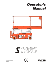
Component Locations
1 Platform controller
2 Platform guard rails
3 Platform extension release pedal
4 Platform entry gate
5 Main Platform
6 Lift Cylinder
7 Entry ladder
8 Drive wheels
9 Emergency lowering knob
10 Ground Control Panel
11 Batteries charger
12 Main power switch
13 Steer Wheels
14 Scissor
15 Safety arms
16 Lanyard anchorage point
17 Platform extension
18 Manual storage container
18
2
1
6
7
8
12
16
15
13
14
17
3
9
10
11
4
5

94553r1 Page 8
September 2017
Micro 19
Controls & Components
Micro 19
Platform Controls
ALWAYS be aware of the machine’s position and of your surroundings
before activating any control function.
CONTROL DESCRIPTION
1
Thumb Rocker Switch Press the thumb rocker switch in either direction to activate steer function.
2
Drive Select
Press this button to select the drive function.
3
Drive Speed Button Press this button to activate the slow or fast drive function.
5
Emergency Stop Switch
Press the EMERGENCY STOP switch at any time to stop all machine functions.
6
LED Display
Indicates the state of battery charge and displays diagnostic codes when necessary.
7
Horn Button
Press to sound warning horn.
Lift Select
8
Proportional Control Handle
4
Turn the button clockwise to the on position to operate the m
achine.
Press this button to select the Lift function.
LIFT
Lift function: Press the Lift Select switch. Squeeze the Function Enable Switch then move the control handle in the direction
indicated by the yellow arrow and the platform will raise. Squeeze the Function Enable Switch then move the control handle in the
direction indicated by the blue arrow and the platform will lower. The descent alarm will sound while the platform is lowering.
Drive function: Press the Drive Select switch. Squeeze the Function Enable Switch then move the control handle in the direction
indicated by the blue arrow on the control panel and the machine will move in the direction that the blue arrow points. Squeeze
the Function Enable Switch then move the control handle in the direction indicated by the yellow arrow on the control panel and
the machine will move in the direction that the yellow arrow points.
9
1 8
2
3
5
6
7
4
DRIVE
Proportionally controls Lift and Lower functions.
Proportionally controls Forward and Reverse travel.
9
Function Enable Switch
Function Enable Switch for LIFT & DRIVE & STEER functions.

94553r1
Micro 19
Page 9
September 2017
Controls & Components
Micro 19
Lower Controls
ALWAYS be aware of the machine’s position and of your surroundings
before activating any control function.
CONTROL DESCRIPTION
1
LED
2
Hour Meter
3
4
Brake Release Switch
Select to operate from the platform control panel.
Select to operate from the base control panel.
Select to stop operation from either control panel.
Emergency Stop Switch
5
Key Switch
PLATFORM
BASE
OFF
6
Platform Lift / Lower Switch
With the Key Switch in the BASE position, move this switch up to lift the platform or down
to lower the platform.
Press the EMERGENCY STOP switch at any time to stop all machine functions.
Turn button clockwise to the on position to operate the machine.
1
2
4
6
5
3
Displays diagnostic codes when necessary.
See page 31 for instructions.

94553r1 Page 10
September 2017
Micro 19
Workplace Inspe ction
Micro 19
Workplace Inspection
DO NOT operate this machine until you have read and understood this manual, have performed the Workplace Inspection,
Pre-Start Inspection and Routine Maintenance, and have completed all the test operations detailed in the Operating
Instructions section.
Inspect the workplace and determine whether the workplace is suitable for safe machine operation. Do this before moving the
machine to the workplace.
Be sure the lift is the correct machine for the job.
Be aware of workplace conditions, and continue to watch for hazards while operating the machine.
Workplace Inspection
Before operating the machine, check the workplace for all possible hazards, including but not
limited to:
• drop-offs or holes, including those concealed by water, ice, mud, etc.
• sloped, unstable or slippery surfaces
• bumps, surface obstructions and debris
• overhead obstructions and electrical conductors
•other objects or equipment
• hazardous locations and atmospheres
• inadequate surface and support to withstand all load forces imposed by the machine
• wind and weather conditions
• the presence of unauthorized personnel
• other possible unsafe conditions
Operating Instructions & Functions Test
DO NOT operate this machine until you have read and understood this manual, have performed the Workplace Inspection,
Pre-Start Inspection and Routine Maintenance, and have completed all the test operations detailed in the Operating
Instructions section.
This section provides instructions and tests for each function of machine operation. Follow all safety rules and instructions. The
operator must conduct inspections and a Functions Test of the machine before each work shift to check that all machine systems are
working properly.
Test the machine on a firm level surface with no debris, drop-offs, potholes or overhead obstructions. Perform each step outlined in
this section.
This machine shall only be operated by trained and authorized personnel. If multiple operators use this machine, all must be trained,
qualified and authorized to use it. New operators must perform a Pre-Start Inspection and Functions Test prior to operating the
machine.
Operators must comply with all employer and job site rules and governmental regulations regarding the use of personal protective
equipment.
DO NOT use a machine that is malfunctioning. If any function does not perform as described, tag the machine and remove for repair
by a qualified service technician. After repairs are completed, a Pre-Start Inspection and Functions Test must be performed before
using the machine.

94553r1
Micro 19
Page 11
September 2017
Micro 19
Operating Instructions & Functions Test
Check the area above and around the machine for obstructions and electrical power lines before
operating the machine. The machine must have space to allow full elevation of platform.
Prestart
•Perform Prestart Inspection (see page 23).
• Check Emergency Stop Switches at the platform controls – turn clockwise to reset.
• Check Main Power/Lower Emergency Stop Switch. Must be in ON position.
Functions Test
1 Select a test area that is firm, level and free of obstruction.
2 Be sure the battery pack is connected.
3 Turn the main power switch to ON (pulled out) position.
At the Ground Controls
ART_4979
ART_5231
ON
OFF
Main Power/
Lower Emergency
Stop Switch
4
Turn the ground red Emergency Stop
button clockwise to the on position
5
Pull out the platform red Emergency Stop
button to the on position.
6 Turn the key switch to ground control.
7
Observe the diagnostic LED readout on the
ECU window.
⊙ Result: The LED
should look like the
picture at right.

94553r1 Page 12
September 2017
Micro 19
Micro 19
Operating Instructions & Functions Test
Test Emergency Stop
Test Up/Down Functions
Check the area above and around the machine for obstructions and electrical power lines before
operating the machine.
A buzzer with different sound frequency is controlled in central system. The descent alarm
sounds at 60 beeps per minute. The alarm that goes off when the machine is not level sounds
at 150 beeps per minute.
10 Turn the Key Switch to off or platform position.
11 Move up and hold the platform up / down switch.
• Result: No function should operate.
12 Turn the Key Switch to ground control position.
13 Move up and hold the Platform Up switch.
• Result: The platform should raise.
14 Move down and hold the Platform Down switch.
• Result: The platform should lower to end. The descent alarm should sound while the
platform is lowering.
Test the Emergency Lowering
15 Activate the up function and raise the platform approximately 2 ft / 60 cm.
16 Pull the emergency lowering knob.
• Result: The platform should lower. The descent alarm will not sound.
At the Platform Controls
17 Turn the Key Switch to platform control.
Test Emergency Stop
18 Push in the platform red Emergency Stop button to the off position.
• Result: No functions should operate.
19 Turn the red Emergency Stop button clockwise to the on position.
• Result: The LED indicator light should come on.
Test the Horn
20 Push the horn button.
• Result: The horn should sound.
ART_4986
Emergency
Lowering
Knob
8 Push in the ground red Emergency Stop button to the off position.
⊙ Result: No functions should operate.
9 Turn the ground red Emergency Stop

94553r1
Micro 19
Page 13
September 2017
Micro 19
Operating Instructions & Functions Test
Test Function Enable and Up/Down Functions
Check the area above and around the machine for obstructions and electrical power lines before
operating the machine.
Test the Steering
identified by the blue left arrow on the control panel.
• Result: The steer wheels should turn in the direction that the blue left arrow points on
the control panel.
31 Depress the thumb rocker switch in the direction identified by the white right arrow
on the control panel.
• Result: The steer wheels should turn in the direction that the white right arrow poin
ts
o
n the control panel.
Test Drive and Braking
32 Press and hold the Function Enable Switch on the control handle.
33 Slowly move the control handle in the direction indicated by the blue up arrow on the
control panel until the machine begins to move, then return the handle to the center
position.
• Result: The machine should move in the direction that the blue up arrow points on th
e
co
ntrol panel, then come to an abrupt stop.
34 Press and hold the Function Enable Switch on the control handle.
35 Slowly move the control handle in the direction indicated by the yellow down arrow
on the control panel until the machine begins to move, then return the handle to the
center position.
• Result: The machine should move in the direction that the yellow down arrow poin
ts
o
n the control panel, then come to an abrupt stop.
Note: The brakes must be able to hold the machine on any slope it is able to climb.
21 Do not hold the function enable switch on the control handle.
22 Slowly move the control handle in the direction indicated by the blue
arrow, then in the direction indicated by the yellow arrow.
⊙ Result: No functions should operate.
23 Press the lift function select button.
24 Press and hold the function enable switch on the control handle.
25 Slowly move the control handle in the direction indicated by the yellow arrow.
⊙ Result: The platform should raise.
26 Release the control handle.
⊙ Result: The platform should stop raising.
27 Press and hold the function enable switch. Slowly move the control handle in the
direction indicated by the blue arrow.
⊙ Result: The platform should lower. The descent alarm should sound while the
platform is lowering.
Note: When performing the steer and drive function tests, stand in the platform
facing the steer end of the machine.
28 Press the drive function select switch.
29 Press and hold the Function Enable Switch on the control handle.
30 Depress the thumb rocker switch on top of the control handle in the direction

94553r1 Page 14
September 2017
Micro 19
Micro 19
Operating Instructions & Functions Test
Test Limited Drive Speed
36 Press the lift Function Enable Switch. Raise the platform approximately 5 ft / 1.5 m from
the ground.
37 Press the drive function sele
ct switch.
3
8
Press a
nd
hold the Function Enable Switch
o
n the control handle.
3
9
Slowly
m
ove
t
he contro
l
handle
t
o the full drive position.
• Result: The maximum achievable drive speed with the platform raised should not
exceed 0.55 ft per second / 16.7 cm/s.
• If the drive speed with the platform raised exceeds 0.55 ft per second / 16.7 cm/s,
immediately tag and remove the machine from service.
Operating Instructions
Check the area above and around the machine for obstructions and electrical power lines before
operating the machine.
Emergency Stop
• Push in the red Main Power/Lower Emergency Stop Switch button to the off
position at the ground controls or the platform controls to stop all machine
functions.
• Repair any function that operates when either red Emergency Stop button is
pushed in.
ART_5231
ON
OFF
Main Power/
Lower Emergency
Stop Switch

94553r1
Micro 19
Page 15
September 2017
Micro 19
Operating Instructions & Functions Test
Emergency Lowering
If the control system fails while the platform is elevated, use the emergency lowering procedure to
safely lower the platform.
Do not climb down the scissor assembly or exit the platform.
The Emergency Lowering System is used to lower the platform in case of power failure.
• Pull the Emergency Lowering Knob to lower the platform.
Operation from Ground
Drive and steer functions are not available from the ground controls.
1 Turn the Key Switch to ground control.
2 Set the red Emergency Stop buttons to the ON position at both the ground and
platform controls.
3 Be sure the battery pack is connected before operating the machine.
Check the area above and around the machine for obstructions and electrical power lines before
operating the machine.
To Position Platform
Move the up/down toggle switch according to the markings on the control panel.
ART_4986
Emergency
Lowering
Knob
ART_4987

94553r1 Page 16
September 2017
Micro 19
Micro 19
Operating Instructions & Functions Test
Operation from Platform
1 Turn the Key Switch to platform control.
2 Set the red Emergency Stop buttons to the ON position at both the ground and
platform controls.
3 Be sure the battery pack is connected before operating the machine.
Check the area above and around the machine for obstructions and electrical power lines before
operating the machine.
To Position Platform
1 Press the lift function select button.
2 Press and hold the Function Enable Switch on the control handle.
3 Move the control handle according to the markings on the control panel.
To Steer
1 Press the drive function select button.
2 Press and hold the Function Enable Switch on the control handle.
3 Turn the steer wheels with the thumb rocker switch located on the top of the control
handle.
ART_4989
Function Enable Switch
Function Enable Switch

94553r1
Micro 19
Page 17
September 2017
Micro 19
Operating Instructions & Functions Test
To Drive
1 Press the drive function select button.
2 Press and hold the Function Enable Switch on the control handle.
• Increase speed: Slowly move the control handle off center.
• Decrease speed: Slowly move the control handle toward center.
• Stop: Return the control handle to center or release the Function Enable Switch.
Use the color-coded direction arrows on the platform controls to identify the direction the
machine will travel.
Machine travel speed is restricted when the platform is raised.
Battery condition will affect machine performance. Machine drive speed and function speed
will drop when the battery level indicator is flashing.
To Reduce Drive Speed
The drive controls can operate in two different drive speed modes.
When the drive speed button light is on, slow drive speed mode is active.
When the button light is off, fast drive speed mode is active.
Press the drive speed button to select the desired drive speed.
Driving On A Slope
Determine the slope and side slope ratings for the machine and determine the slope grade.
Maximum forward/rearward slope rating, stowed position 25%.
Maximum side slope rating, stowed position 5°.
Note: Slope rating is subject to ground conditions and adequate traction.
Press the drive speed button to the slow drive speed mode.
To determine the slope grade
Measure the slope with a digital inclinometer OR use the following procedure.
You w i l l n e ed:
• Carpenter's level
• Straight piece of wood, at least 3.3 ft / 1 m long
•Tape measure
Lay the piece of wood on the slope.
At the downhill end, lay the level on the top edge of the piece of wood and lift the end until the
piece of wood is level.
While holding the piece of wood level, measure the distance from the bottom of the piece of
wood to the ground.
Divide the tape measure distance (rise) by the length of the piece of wood (run) and multiply
by 100.
Example:
Run = 12 ft / 3.6 m
Rise = 12 in / 0.3 m
12 in ÷ 12 ft = 0.083 × 100 = 8.3%
0.3 m ÷ 3.6 m = 0.083 × 100 = 8.3%
If the slope exceeds the maximum slope or side slope rating, the machine must be winched or
transported up or down the slope. See Transport and Lifting section.
ART_4983
Function Enable Switch

94553r1 Page 18
September 2017
Micro 19
Micro 19
Operating Instructions & Functions Test
Operation from Ground with Controller
Use extreme caution when operating the machine with the controller from the ground
Maintain safe distances between operator, machine and fixed objects.
Be aware of the direction the machine will travel when using the controller.
Battery Level Indicator
Use the LED diagnostic readout to determine the battery level.
Maintenance Lock
1 Raise the platform approximately 7.2ft / 2.2m from the ground.
2 Rotate the Maintenance Lock away from the machine and let it hang down.
3 Lower the platform until the Maintenance Lock rests securely on the link.
Keep clear of the Maintenance Lock when lowering the platform.
Don't engage the Maintenance Lock unless the platform in empty of tools and material.
To Extend and Retract the Deck Extension
1 Press the platform lock pin foot pedal on the extension deck.
2 Push the platform extension guardrail to extend the platform to the desired position.
Do not stand on the platform extension while extending or retracting it.
FULL LOW
ART_4984
ART_4995
Maintenance
Lock
ART_4996
Deck Extension
Release Pedal
/