Page is loading ...

GRUNDFOS DATA BOOKLET
SMART Digital S
DIGITAL DOSING up to 30 l/h
DDA, DDC, DDE
Pumps and accessories

Table of contents
2
SMART Digital S
1. General data 3
Performance range . . . . . . . . . . . . . . . . . . . . . . . . . . . . . . . . . . . . . . . . . . . . . . . . . . . . . . . . . . . . . . . . . . . . . . . . . . . . 3
Features at a glance . . . . . . . . . . . . . . . . . . . . . . . . . . . . . . . . . . . . . . . . . . . . . . . . . . . . . . . . . . . . . . . . . . . . . . . . . . . 4
2. Identification 6
Type key . . . . . . . . . . . . . . . . . . . . . . . . . . . . . . . . . . . . . . . . . . . . . . . . . . . . . . . . . . . . . . . . . . . . . . . . . . . . . . . . . . . . 6
3. Functions 7
Overview of functions. . . . . . . . . . . . . . . . . . . . . . . . . . . . . . . . . . . . . . . . . . . . . . . . . . . . . . . . . . . . . . . . . . . . . . . . . . . 7
Functional description . . . . . . . . . . . . . . . . . . . . . . . . . . . . . . . . . . . . . . . . . . . . . . . . . . . . . . . . . . . . . . . . . . . . . . . . . . 8
Control cube DDA and DDC . . . . . . . . . . . . . . . . . . . . . . . . . . . . . . . . . . . . . . . . . . . . . . . . . . . . . . . . . . . . . . . . . . . . . 9
Menu . . . . . . . . . . . . . . . . . . . . . . . . . . . . . . . . . . . . . . . . . . . . . . . . . . . . . . . . . . . . . . . . . . . . . . . . . . . . . . . . . . . . . . 10
Operation modes . . . . . . . . . . . . . . . . . . . . . . . . . . . . . . . . . . . . . . . . . . . . . . . . . . . . . . . . . . . . . . . . . . . . . . . . . . . . . 11
Functions . . . . . . . . . . . . . . . . . . . . . . . . . . . . . . . . . . . . . . . . . . . . . . . . . . . . . . . . . . . . . . . . . . . . . . . . . . . . . . . . . . . 13
Wiring diagram, DDA . . . . . . . . . . . . . . . . . . . . . . . . . . . . . . . . . . . . . . . . . . . . . . . . . . . . . . . . . . . . . . . . . . . . . . . . . . 19
Wiring diagram, DDC . . . . . . . . . . . . . . . . . . . . . . . . . . . . . . . . . . . . . . . . . . . . . . . . . . . . . . . . . . . . . . . . . . . . . . . . . . 20
Wiring diagram, DDE-PR, -P . . . . . . . . . . . . . . . . . . . . . . . . . . . . . . . . . . . . . . . . . . . . . . . . . . . . . . . . . . . . . . . . . . . . 21
4. Construction 22
DDA and DDC . . . . . . . . . . . . . . . . . . . . . . . . . . . . . . . . . . . . . . . . . . . . . . . . . . . . . . . . . . . . . . . . . . . . . . . . . . . . . . . 22
DDE . . . . . . . . . . . . . . . . . . . . . . . . . . . . . . . . . . . . . . . . . . . . . . . . . . . . . . . . . . . . . . . . . . . . . . . . . . . . . . . . . . . . . . . 23
5. Dimensions 24
DDA and DDC . . . . . . . . . . . . . . . . . . . . . . . . . . . . . . . . . . . . . . . . . . . . . . . . . . . . . . . . . . . . . . . . . . . . . . . . . . . . . . . 24
DDE . . . . . . . . . . . . . . . . . . . . . . . . . . . . . . . . . . . . . . . . . . . . . . . . . . . . . . . . . . . . . . . . . . . . . . . . . . . . . . . . . . . . . . . 24
6. Technical data 25
DDA . . . . . . . . . . . . . . . . . . . . . . . . . . . . . . . . . . . . . . . . . . . . . . . . . . . . . . . . . . . . . . . . . . . . . . . . . . . . . . . . . . . . . . . 25
DDC . . . . . . . . . . . . . . . . . . . . . . . . . . . . . . . . . . . . . . . . . . . . . . . . . . . . . . . . . . . . . . . . . . . . . . . . . . . . . . . . . . . . . . . 26
DDE . . . . . . . . . . . . . . . . . . . . . . . . . . . . . . . . . . . . . . . . . . . . . . . . . . . . . . . . . . . . . . . . . . . . . . . . . . . . . . . . . . . . . . . 27
7. Pump selection 28
DDA, standard range . . . . . . . . . . . . . . . . . . . . . . . . . . . . . . . . . . . . . . . . . . . . . . . . . . . . . . . . . . . . . . . . . . . . . . . . . . 28
DDC, standard range. . . . . . . . . . . . . . . . . . . . . . . . . . . . . . . . . . . . . . . . . . . . . . . . . . . . . . . . . . . . . . . . . . . . . . . . . . 29
DDE, standard range . . . . . . . . . . . . . . . . . . . . . . . . . . . . . . . . . . . . . . . . . . . . . . . . . . . . . . . . . . . . . . . . . . . . . . . . . . 30
DDA, DDC, DDE, non-standard range. . . . . . . . . . . . . . . . . . . . . . . . . . . . . . . . . . . . . . . . . . . . . . . . . . . . . . . . . . . . . 31
8. Accessories for small dosing pumps up to 60 l/h 33
Accessories overview . . . . . . . . . . . . . . . . . . . . . . . . . . . . . . . . . . . . . . . . . . . . . . . . . . . . . . . . . . . . . . . . . . . . . . . . . 33
Installation kits for dosing pumps. . . . . . . . . . . . . . . . . . . . . . . . . . . . . . . . . . . . . . . . . . . . . . . . . . . . . . . . . . . . . . . . . 34
Cables and plugs . . . . . . . . . . . . . . . . . . . . . . . . . . . . . . . . . . . . . . . . . . . . . . . . . . . . . . . . . . . . . . . . . . . . . . . . . . . . . 35
E-box for SMART digital S DDA . . . . . . . . . . . . . . . . . . . . . . . . . . . . . . . . . . . . . . . . . . . . . . . . . . . . . . . . . . . . . . . . . 36
Hoses. . . . . . . . . . . . . . . . . . . . . . . . . . . . . . . . . . . . . . . . . . . . . . . . . . . . . . . . . . . . . . . . . . . . . . . . . . . . . . . . . . . . . . 37
Foot valves FV . . . . . . . . . . . . . . . . . . . . . . . . . . . . . . . . . . . . . . . . . . . . . . . . . . . . . . . . . . . . . . . . . . . . . . . . . . . . . . . 38
Rigid suction lances RSL . . . . . . . . . . . . . . . . . . . . . . . . . . . . . . . . . . . . . . . . . . . . . . . . . . . . . . . . . . . . . . . . . . . . . . . 39
Injection units . . . . . . . . . . . . . . . . . . . . . . . . . . . . . . . . . . . . . . . . . . . . . . . . . . . . . . . . . . . . . . . . . . . . . . . . . . . . . . . . 43
Multi-function valves, pressure relief valves, pressure loading valves. . . . . . . . . . . . . . . . . . . . . . . . . . . . . . . . . . . . . 45
Pump connection kits and inlay kits . . . . . . . . . . . . . . . . . . . . . . . . . . . . . . . . . . . . . . . . . . . . . . . . . . . . . . . . . . . . . . . 48
Adapters. . . . . . . . . . . . . . . . . . . . . . . . . . . . . . . . . . . . . . . . . . . . . . . . . . . . . . . . . . . . . . . . . . . . . . . . . . . . . . . . . . . . 49
Dosing tanks . . . . . . . . . . . . . . . . . . . . . . . . . . . . . . . . . . . . . . . . . . . . . . . . . . . . . . . . . . . . . . . . . . . . . . . . . . . . . . . . 51
Water meter . . . . . . . . . . . . . . . . . . . . . . . . . . . . . . . . . . . . . . . . . . . . . . . . . . . . . . . . . . . . . . . . . . . . . . . . . . . . . . . . . 55
9. Pumped liquids 56
10. Grundfos Product Center 57

General data
3
SMART Digital S
1
1. General data
Performance range
Fig. 1 Performance range
TM04 1480 0410
Q [l/h]
10
7
6
12
15
17
30
4
0
p
[bar]
16
9
7.5
DDA 7.5-16
DDA 12-10
DDA 17-7
DDA 30-4
DDC 15-4
DDE 15-4
DDC 9-7
DDC 6-10
DDE 6-10

General data
4
SMART Digital S
1
Features at a glance
Fig. 2 DDA, DDC, DDE
Digital Dosing
TM
The SMART Digital S generation DDA, DDC and DDE
with powerful variable-speed stepper motor brings
state-of-the-art technology to perfection.
Combined expert knowledge and the patented
solutions set future standards. Traditional technologies
such as stroke length or stroke frequency adjustment
with synchronous motor or solenoid drive become a
thing of the past.
Unique flexibility with only a few variants
The included click-stop mounting plate makes the
pump more flexible. Three different positions are
possible without using any additional accessories,
such as wall brackets. Service and pump exchange
can now be done easily and fast just by clicking the
pump in and out of the mounting plate.
The control cube on the DDA and DDC pump can be
lifted and turned easily into three different positions:
front, left or right.
Fig. 3 Modularity of the control cube
A turn-down ratio of up to 1:3000, a wide supply
voltage range (100-240 V; 50/60 Hz), combined
connection sets and other features reduce the models
and variants to a minimum.
Precise and easy setting / usability and interaction
The operator can easily install the pump and set it to
discharge exactly the quantity of dosing liquid required
for the application. In the display, the setting of the
pump is read out directly, the flow is shown in ml/h, l/h,
or gph.
The click wheel (turn-and-push knob) and the
graphical LC display with plain-text menu in more than
25 languages make commissioning and operation
intuitive. As the LCD is backlit in different colours, the
pump status can be seen from a distance (traffic-light
concept).
Fig. 4 Display DDA, DDC
Thanks to a variety of operation modes, signal inputs
and outputs, the pump can easily be integrated into
every process.
Advanced process reliability
An intelligent drive and microprocessor control
ensures that dosing is performed precisely and with
low pulsation, even if the pump is dosing high-viscosity
or degassing liquids. Malfunctions, caused e.g. by air
bubbles, are detected quickly by the maintenance-free
FlowControl system and then displayed in the alarm
menu.
The AutoFlowAdapt function automatically adjusts the
pump according to the process conditions, e.g. varying
backpressure. The integrated flow measurement
makes additional monitoring and control equipment
redundant.
Designed to save costs
In general, the investment for a dosing pump
installation is low compared to its life cycle costs
including the cost of the chemicals. The following
features make the SMART Digital S DDA, DDC and
DDE pumps contribute to low life cycle costs:
• No underdosing or overdosing due to high dosing
accuracy and FlowControl
• Longer maintenance intervals thanks to the
universal chemical resistance of the full-PTFE
diaphragm
• Reduced energy consumption thanks to
state-of-the-art drive technology.
TM06 8988 2417TM04 1662 2610
TM04 1661 2610

General data
5
SMART Digital S
1
Three application-oriented type ranges
DDA: High-end pump range for extended flow and
pressure ranges with sensor-based FlowControl and
measurement functions for challenging industrial
applications, e.g.
• Process water
• Food and beverage
• Ultrafiltration and reverse osmosis
• Pulp and paper
• Boiler feed water
• CIP (Cleaning-In-Place).
DDC: User-friendly pump range with standard inputs
and outputs for common applications, e.g.
• Drinking water
• Waste water
• Swimming pool water
• Cooling tower
• Chemical industry.
DDE: Low-budget pump range with basic functions
including manual operation or control via PLC for OEM
applications, e.g.
•Car wash
• Irrigation.

Identification
6
SMART Digital S
2
2. Identification
Type key
Example: DDA 7.5-16 AR-PP/V/C-F-3 1 U2U2 F G
* Installation set: Including 2 pump connections, foot valve, injection
unit, 6 m PE discharge hose, 2 m PVC suction hose, 2 m PVC
deaeration hose (4/6 mm)
** PVC dosing heads only up to 10 bar
Type range
DDA 7.5-16 AR-PP/V/C-F-3 1 U2U2 F G
DDA
DDC
DDE
Max. flow [l/h]
DDA 7.5-16 AR-PP/V/C-F-3 1 U2U2 F G
Maximum pressure [bar]
DDA 7.5-16 AR-PP/V/C-F-3 1 U2U2 F G
Control variant
DDA 7.5-16 AR-PP/V/C-F-3 1 U2U2 F G
BBasic (DDE)
P B with pulse mode (DDE)
PR P with relay output (DDE)
A Standard (DDC)
AR A with alarm relay and analog input (DDA, DDC)
FC AR with FlowControl (DDA)
FCM FC with flow measurement (DDA)
Dosing head variant
DDA 7.5-16 AR-PP/V/C-F-3 1 U2U2 F G
PP Polypropylene
PVC Polyvinyl chloride**
PV PVDF (polyvinylidene fluoride)
SS Stainless steel 1.4401
Gasket material
DDA 7.5-16 AR-PP/V/C-F-3 1 U2U2 F G
E EPDM
VFKM
TPTFE
Valve ball material
DDA 7.5-16 AR-PP/V/C-F-3 1 U2U2 F G
C Ceramic
SS Stainless steel 1.4401
Control cube position
DDA 7.5-16 AR-PP/V/C-F-3 1 U2U2 F G
F Front-mounted (change to left and right possible)
X No control cube (DDE)
Supply voltage
DDA 7.5-16 AR-PP/V/C-F-3 1 U2U2 F G
3 1 x 100-240 V, 50/60 Hz
Valve type
DDA 7.5-16 AR-PP/V/C-F-3 1 U2U2 F G
1 Standard
2 Spring-loaded
0.1 bar suction opening pressure
0.1 bar discharge opening pressure
Connection, suction/discharge
DDA 7.5-16 AR-PP/V/C-F-3 1 U2U2 F G
U2U2
Union nut G 5/8" with parts for hose connection
4/6 mm, 6/9 mm, 6/12 mm, 9/12 mm
U7U7
Union nut G 5/8" with parts for hose connection
0.17" x 1/4"; 1/4" x 3/8"; 3/8" x 1/2"
AA
Union nut G 5/8" with threaded connection Rp 1/4",
internal thread
VV
Union nut G 5/8" with threaded connection 1/4" NPT,
internal thread
XX No connections included
I001
*
Hose 4/6 mm (up to 7.5 l/h, 13 bar)
I002
*
Hose 9/12 mm (up to 60 l/h, 9 bar)
I003
*
Hose 0.17" x 1/4" (up to 7.5 l/h, 13 bar)
I004
*
Hose 3/8" x 1/2" (up to 60 l/h, 10 bar)
Mains plug
DDA 7.5-16 AR-PP/V/C-F-3 1 U2U2 F G
FEU
B USA, Canada
GUK
I Australia, New Zealand
E Switzerland
J Japan
L Argentina
Design/approval
DDA 7.5-16 AR-PP/V/C-F-3 1 U2U2 F G
G Grundfos red
A Grundfos green
B Grundfos black
X Neutral/black
C China approval
Special variant
DDA 7.5-16 AR-PP/V/C-F-3 1 U2U2 F GC3
C3 Inspection Certificate 3.1 (EN 10204)

Functions
7
SMART Digital S
3
3. Functions
Overview of functions
* DDE-PR: relay 1: alarm; relay 2: low-level signal, stroke signal, pulse input
DDA DDC DDE
Control variant: FCM FC AR AR A PR P B
General
Digital Dosing: Internal stroke speed and frequency control ●●●● ●●●●
Mounting plate (basic/wall mounting) ●●●● ●●●●
Control panel, see page 9
Control cube mountable in three positions: front, left, right ●●● ● ●
Control panel position: front-fitted ●●●
Transparent protective cover for control elements ●●● ● ●
Capacity setting in millilitres, litres or US-gallons ●●● ● ●
Graphical display with background light in four colours for status
indication: white, green, yellow, red
●●● ● ●
Plain-text menu in different languages ●●● ● ●
Turn-and-push knob (click wheel) for easy navigation ●●● ● ●
Capacity adjustment knob (0.1 - 100 %) ●●●
Start/Stop key ●●● ● ●
100 % key (deaearation) ●●●● ●●●
Operation mode switch (manual/pulse) ●●
Operation modes, see page 11
Manual speed control ●●●● ●●●●
Pulse control in ml/pulse ●●● ● ●
Pulse control (1:n) ●●
Analog control 0/4-20 mA ●●● ●
Batch control (pulse-based) ●●●
Dosing timer cycle ●●●
Dosing timer week ●●●
Fieldbus control ●●●
Functions, see page 13
Auto deaeration also during pump standby ●●●
FlowControl system with selective fault diagnosis ●●
Pressure monitoring (min/max) ●●
Flow measurement ●
AutoFlowAdapt ●
SlowMode (anti-cavitation) ●●● ● ●
Calibration mode ●●● ● ●
Scaling of analog input ●●●
Service information display ●●● ● ●
Relay setting: alarm, warning, stroke signal, pump dosing, pulse input* ●●● ● ●
Relay setting (additionally): timer cycle, timer week ●●●
Inputs/outputs, see page 14
Input for external stop ●●●● ●●●
Input for pulse control ●●●● ●●●
Input for analog 0/4-20 mA control ●●● ●
Input for low-level signal ●●●● ●●●
Input for empty tank signal ●●●● ●●●
Output relay (2 relays) ●●● ● ●
Output analog 0/4-20 mA ●●●
Input/Output for GENIbus ●●●
Input/Output for E-box (e.g. E-box 150 with Profibus DP) ●●●

Functions
8
SMART Digital S
3
Functional description
The electronically controlled variable-speed motor
(stepper motor) of the DDA, DDC and DDE pumps
provides optimum control of the stroke speed.
The duration of each discharge stroke varies
according to the capacity set, resulting in optimum
discharge flow in any operating situation, while the
duration of each suction stroke is constant (see figure
below).
The advantages are as follows:
• The pump always operates at full stroke length,
irrespective of the capacity set; this ensures
optimum accuracy, priming and suction.
• A capacity range of up to 1:3000 (turn-down ratio)
reduces variants and spare parts.
• Smooth and continuous dosing ensuring an
optimum mixing ratio at the injection point without
needing static mixers.
• Significant reduction of pressure peaks, preventing
mechanical stress on wearing parts such as
diaphragm, tubes, connections, resulting in
extended maintenance intervals.
• The installation is less affected by long suction and
discharge lines.
• Easier dosing of high-viscosity and degassing
liquids (SlowMode).
The optimum dosing control shown below takes place
in any operation mode.
Fig. 5 Relation between stroke-frequency adjustment and capacity
TM04 1481 0410
100 %
50 %
10 %
Discharge
Discharge
Discharge
Duration
Duration
Duration
Suction
Suction
Suction
Capacity
setting
Duration
10 %
Discharge
Suction
SlowMode
50 %
Extended suction stroke (SlowMode)
-
-
-

Functions
9
SMART Digital S
3
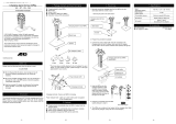
Control cube DDA and DDC
DDA and DDC pumps are supplied with front-mounted
control cube. The position of the control cube can
easily be changed by unfastening 2 screws, lifting the
cube, turning it to the left or to the right and fastening
both screws again.
Fig. 6 Two of three possible control cube positions
Operating elements DDA and DDC
Fig. 7 Operating elements DDA and DDC
The click wheel guides the user quickly and easily
through the plain-text menu.
If the maximum capacity is required over a short period
of time, for example during start-up, press the 100 %
key. To set the pump to run for a specific number of
seconds at maximum capacity, press the 100 % key
and turn the click wheel clockwise simultaneously.
Operating elements DDE
Fig. 8 Operating elements DDE
With the capacity adjustment knob the capacity of the
pump can easily be adjusted in % of the maximum
flow.
Applies to DDE-PR, DDE-P
When holding down the operation mode switch, the
pump changes from manual operation to pulse mode
or vice versa.
If the maximum capacity is required over a short period
of time, for example during start-up, press the 100 %
key.
Depending on the selected operation mode, the
respective status LED (pulse or manual) is activated
according to the following table:
TM06 9584 2517TM06 8989 1517
Pos. Description
1 Graphical LC display
2 [Start/Stop] key
3 Click wheel
4 [100%] key
7.49 l/h
Manual
7.5
l/h
Operation
1
2
3
4
TM04 1596 1817
Pos. Description
1 Status LED pulse (DDE-PR and DDE-P)
2 Operation mode switch (DDE-PR and DDE-P)
3 Status LED manual
4 Capacity adjustment knob
5 Logarithmic scale
6 100 % key (DDE-PR and DDE-P)
7 Mechanical lock
LED colour Pump status
Green (flashing) Stopped
Green Running
Red-green (flashing) External stop
Yellow Low level (warning)
Red Empty tank (alarm)
Red (flashing) Motor blocked (alarm)
100%
0%
0.15
0.2
0.3
0.4
0.5
0.6
0.8
1.5
2
3
4
5
6
8
15
20
30
40
50
60
80
10
1
1
3
2
4
5
6
7
100 %

Functions
10
SMART Digital S
3
Menu
The DDA and DDC dosing pumps feature a user-friendly plain-text menu. The menu consists of 4 tabs: Operation;
Info; Alarm; Setup. During initial start-up, all menu text appears in the English language. The menu can be
set to display other languages.
This example applies to DDA pumps:
Fig. 9 Menu overview (example of main menus)
The menu text appears in more than 25 languages on a big graphical display, backlit in four different colours according
to the traffic light concept.
TM04 1553 1210
Alarm
1 12.12.2009 13:34
Low level
2
Empty
11.12.2009 14:34
Setup
Language
Operation mode
Analog output
SlowMode
.............................
English >
Manual >
Input >
Off >
Info
Fr 12.12.2009
Counter
Service
Service kit
.............................
12:34
>
-
7.49 l/h
Manual
l/h
Operation
7.50
Display Fault Pump status
White - Stop Standby
Green - Running
Yellow Warning Stop Standby Running
Red Alarm Stop Standby

Functions
11
SMART Digital S
3
Operation modes
Manual control
The pump ensures constant dosing according to
the quantity set in l/h or ml/h or gph by means of the
click wheel. The pump automatically changes between
the measuring units.
Setting range
* When the SlowMode function is enabled the max. flow is reduced
(see page 13)
Pulse control
The pump doses in proportion to an external
potential-free pulse signal, for example from a water
meter. There is no direct relation between pulses and
dosing strokes. The pump automatically calculates its
optimal speed to ensure that the required quantity is
dosed for each incoming pulse.
Applies to DDA and DDC
The quantity to be dosed is set in ml/pulse. The pump
adjusts its speed according to two factors:
• the frequency of external pulses
• the set quantity per pulse.
Setting range
The frequency of external pulses is multiplied by the
set quantity. If the product exceeds the maximum flow
of the pump, a maximum of 65,000 pulses can be
stored for later processing with the Memory pulse
function, when activated.
Applies to DDE-PR, DDE-P control variant
The dosing quantity per pulse is adjusted with the
adjustment knob according to the scale from 0.1 to
100 % of the stroke volume. The pump adjusts its
speed according to two factors:
• the frequency of external pulses
• the set percentage of stroke volume.
Setting range, DDE-PR, DDE-P
Analog 0/4-20 mA control
Applies to DDA and DDC-AR control variant
The pump ensures dosing according to an external
analog signal. The dosed capacity is proportional to
the input value in mA.
Fig. 10 0/4-20 mA control
Applies to DDA
With the analog scaling function, the curve can be
individually drawn between two arbitrary points: l
1
/Q
1
and l
2
/Q
2
.
Fig. 11 Analog scaling
Pump type
Setting range*
From [l/h] To [l/h]
DDA 7.5-16 0.0025 7.5
DDA 12-10 0.0120 12.0
DDA 17-7 0.0170 17.0
DDA 30-4 0.0300 30.0
DDC 6-10 0.0060 6.0
DDC 9-7 0.0090 9.0
DDC 15-4 0.0150 15.0
DDE 6-10 0.0060 6.0
DDE 15-4 0.0150 15.0
Pump type Setting range [ml/pulse]
DDA 7.5-16 0.0015 - 14.9
DDA 12-10 0.0029 - 29.0
DDA 17-7 0.0031 - 31.0
DDA 30-4 0.0062 - 62.0
DDC 6-10 0.0016 - 16.2
DDC 9-7 0.0017 - 16.8
DDC 15-4 0.0032 - 31.6
Pump type Setting range [ml/pulse]
DDE 6-10 0.0008 - 0.81
DDE 15-4 0.0016 - 1.58
Operation mode Input signal Dosing capacity
4-20
≤ 4.1 mA 0 %
≥ 19.8 mA 100 %
0-20
≤ 0.1 mA 0 %
≥ 19.8 mA 100 %
TM04 1574 1410TM04 1575 1410
0
Q [%]
0 - 20 mA
4 - 20 mA
[mA]
4
2081216
100
80
0
60
40
20
Dosing capacity
Input signal
0
Q [%]
[mA]
4 2081216
100
80
0
60
40
20
I / Q
1 1
I / Q
2 2
I ' / Q '
1 1
I ' / Q '
2 2
Dosing capacity
Input signal

Functions
12
SMART Digital S
3
Pulse-based batch control
Applies to DDA
The set quantity is dosed in batches within the set
dosing time (t
1
). A batch is dosed every time the pump
receives an external pulse. If the pump receives new
pulses before a batch is completed, these pulses will
be ignored. In the event of interrupts such as external
stop or alarm, incoming pulses will also be ignored.
After ending of the interrupts, a new batch will be
dosed with the next incoming pulse.
Fig. 12 Pulse-based batch control
Setting range
* Due to the digital motor control, down to 1/8 of the dosing volume
can be dosed.
Dosing timer cycle
Applies to DDA
After a start delay (t
2
) the set batch volume is
repeatedly dosed in the set cycle time (t
3
). The dosing
time (t
1
) can be adjusted. Batch dosing is stopped
during any interrupt, e.g. power supply failure or
external stop while the time continues running in the
background (real-time clock). After ending of the
interrupt, batch dosing proceeds according to the
current status in the timeline.
Fig. 13 Dosing timer cycle
Setting range
The batch volume setting range corresponds to the
pulse-based batch control setting range.
Dosing timer week
Applies to DDA
The integrated real-time clock features also batch
dosing based on a weekly period. There is a maximum
of 16 procedures per week. Each dosing procedure
consists of:
• Batch volume
• Dosing time
• Start time
• 1 to 7 weekdays (Monday to Sunday).
In case several procedures are overlapping, the
procedure with the highest flow rate has the highest
priority. Batch dosing is stopped during any interrupt,
e.g. power supply failure or external stop, while the
time continues running in the background (real-time
clock). After ending of the interrupt, batch dosing
proceeds according to the current status in the
timeline.
Fig. 14 Dosing timer week (example with 4 procedures)
Setting range
The batch volume setting range corresponds to the
pulse-based batch control setting range.
TM04 1578 2010
Pump type
Setting range
From
[ml/batch]
To [l/batch] Resolution [ml]*
DDA 7.5-16 0.74 999 0.09
DDA 12-10 1.45 999 0.18
DDA 17-7 1.55 999 0.19
DDA 30-4 3.10 999 0.39
TM04 1577 1410
Batch volume
Pulse Pulse
t
1
t
1
Batch volume
t
1
t
1
t
3
t
2
TM04 1576 1410
0:00
6:00
12:00
18:00
0:00
33333
3
3
22
1
4
4
11 1
1
Mo Tu We Th Fr Sa Su

Functions
13
SMART Digital S
3
Functions
SlowMode
Applies to DDA, DDC
When the SlowMode function (anti-cavitation) is
selected, the pump extends and smooths its suction
stroke. This results in a softer suction stroke.
The SlowMode function is used in these situations:
• when pumping high-viscosity liquids
• when pumping degassing liquids
• when the suction line is long
• when the suction lift is high.
Depending on the application, the motor speed during
the suction stroke can be reduced individually to
approximately 50 % or 25 % of the normal motor
speed.
The maximum pump capacity is reduced accordingly.
See pages 25 and 26 for further details.
Auto deaeration
Applies to DDA
The auto deaeration function avoids breakdown of the
dosing process due to air-locking, when dosing
degassing liquids such as sodium hypochlorite.
During long dosing breaks, e.g. at the weekend or
overnight, air-bubbles can form in the suction line and
get into the dosing head. If too much air is in the
dosing head, and the dosing process is started again,
no liquid will be dosed (air-lock). Software-controlled
diaphragm movements at regular intervals encourage
the air bubbles to rise and finally to be displaced out of
the dosing head.
These movements are executed
• when the pump is not stopped and
• during dosing breaks (e.g. external stop or no
incoming pulses).
Calibration
Applies to DDA and DDC
The pump is calibrated in the factory at the nominal
pressure of the respective pump type (see maximum
pressure Technical data page 25, 26). After start-up,
the dosing pump can be calibrated for the actual
installation to ensure that the displayed value (ml, l or
gph) is correct. A calibration program in the setup
menu facilitates this process. The AutoFlowAdapt
function keeps the dosing precision (DDA-FCM control
variant), even if the backpressure changes.
For the description of the AutoFlowAdapt function, see
page 18.
External stop
Applies to DDA, DDC, DDE-PR, DDE-P
With the external stop function, the pump can be
stopped from a remote place via an external contact. It
is not recommended to switch on and off the power
supply as it was usual when working with a
conventional dosing pump. When working with
microprocessor-controlled digital dosing pumps, the
external stop signal has to be used, in order to keep
the optimal dosing precision and to prevent damages
to the electronics.
When activating the external stop signal, the pump
changes from running
to standby . The operation
display shows an activated external stop .
The signal input can be set to normally open (default)
or normally closed contact.
Counters
Applies to DDA and DDC
The pump displays resettable and non-resettable
counters in the info menu tab.
Counter Description Resettable
Volume
Accumulated dosed quantity in litres or
US gallons
Yes
Operating
hours
Accumulated number of operating hours
(power-on)
No
Motor
runtime
Accumulated number of motor runtime
hours
No
Strokes Accumulated number of dosing strokes No
Power on/off
Accumulated number of times the mains
supply has been switched on
No

Functions
14
SMART Digital S
3
Service display
Applies to DDA, DDC
Due to the optimised construction and the smooth
digital dosing principle, the service periods are more
than twice as long, if compared to conventional pumps.
However, the wear parts have to be exchanged in
regular intervals in order to keep the dosing precision
and the process reliability at a high level. The service
display in the pump shows when service of the wear
parts is required. The displayed service kit product
number makes service more convenient. The following
information is displayed in the Info display:
The following service messages appear, depending on
what happens first:
* Applies to DDA only
In case of difficult liquids the service intervals can be
shorter and service has to be performed earlier.
Level control
Applies to DDA, DDC, DDE-PR and DDE-P
The pump can be connected to a dual level control unit
for monitoring of the chemical level in the tank. The
pump can react to two level signals:
* Depending on the pump model and settings, the relay outputs can
be activated (see Relay output, page 14)
Relay output
Applies to DDA, DDC-AR and DDE-PR
The pump can activate 2 external signals by means of
built-in relays switched via internal potential-free
contacts. Depending on the process control
requirements, the following relay output settings can
be chosen:
Applies to DDA and DDC-AR
* default setting
Applies to DDE-PR control variant
* default setting
Display Description
Service
-
Soon
Now
No service required
Order parts for service soon
Service must be performed now
Service kit
8-digit Grundfos
product number
The service kit contains all parts
needed for standard maintenance:
diaphragm + valves
Reset service system
After performing the service, reset
the system
Display
Motor runtime
[h]
Regular intervals
[months]*
Service soon 7,500 23
Service now 8,000 24
Level sensors
Pump reaction*
DDA, DDC DDE-PR, DDE-P
Low-level signal
• Display is yellow
(Warning)
• is flashing
• Pump continues
running
• LED lights up in
yellow
• Pump continues
running
Empty tank
signal
• Display is red (Alarm)
• is flashing
• Pump stops
• LED lights up in red
• Pump stops
Signal
Description
Relay 1 Relay 2
Alarm* Alarm
Display red, pump stopped
(e.g. empty tank signal, etc.)
Warning* Warning
Display yellow, pump running
(low level signal, etc.)
Stroke signal Stroke signal Every completed stroke
Pump dosing Pump dosing* Pump is running and dosing
Pulse input Pulse input Every pulse coming in from pulse input
Bus control Bus control
Set by a command in the Bus
communication function (page 15)
(only DDA)
Timer cycle
Timer can be set in menu: on-time,
cycle-time, start delay (only DDA)
Timer week
Timer can be set in menu: procedure,
on-time, start time and weekdays (only
DDA)
Contact type
NO* NO* Normally Open Contact
NC NC Normally Closed Contact
Signal
Description
Relay 1 Relay 2
Alarm* Empty tank, motor blocked
Low level* Low level tank
Stroke signal Every completed stroke
Pulse input Every pulse coming in from pulse input
Contact type
NO* NO* Normally Open Contact
NC NC Normally Closed Contact

Functions
15
SMART Digital S
3
Analog output
Applies to DDA
In addition to the analog input (operation mode: analog
0/4-20 mA) the pump is also equipped with an analog
0/4-20 mA output signal. Depending on the process
control requirements, the following analog output
settings are available:
* Output signal is calculated based on motor speed and pump status
(target flow rate).
Bus communication
Applies to DDA
The pump is equipped with a built-in module for
GENIbus communication. With the additional E-Box
module (please see page 36) the pump can be
integrated into a fieldbus network.
The bus communication possibilities enable remote
monitoring and setting via the fieldbus system.
Fig. 15 DDA with E-box
Key lock and mechanical lock
Applies to DDA, DDC
To protect the pump from maloperation, a key lock can
be set by entering a 4-digit PIN-code. When the pump
is locked, it is still possible to navigate through the
menus Alarm and Info and to acknowledge
alarms. Two levels of protection are available:
• Settings: the keys and are still available.
• Settings + keys: the keys and are also
locked.
For temporary (2 minutes) or final deactivation the
preset 4-digit pin-code has to be entered again.
Applies to DDE
The adjustment knob can be locked with a locking
screw to fix the current setting.
Basic settings
Applies to DDA, DDC
With load factory settings, the pump can be reset to
the default settings. In addition, with save customer
settings, the current configuration of the pump is
stored and can be activated later by load customer
settings. The latest saved configuration is stored in the
memory.
Units
Applies to DDA, DDC
It is possible to select metric units (litre/millilitre/bar) or
US units (US gallons/psi). Depending on the operation
mode and menu, the following units are displayed:
Setting
Description of analog
output signal
Control variant
FCM FC AR
Output = Input
Analog feedback signal (not
for master-slave application).
The analog input signal is
mapped 1:1 to the analog
output.
XXX
Actual flow
Flow measured in the dosing
head
(Flow Measurement page 18)
XX*X*
Backpressure
Backpressure measured in
the dosing head
(Pressure monitoring page 18)
XX
Bus control
Set by a command in the bus
communication (see below)
XXX
TM04 1640 2617
Operation mode/Function Metric units US units
Manual control ml/h or l/h gph
Pulse control ml/ ml/
Analog 0/4-20 mA control ml/h or l/h gph
Batch control
(pulse- or timer-based)
ml or l gal
Calibration ml ml
Volume counter l gal
Pressure monitoring bar psi
100%
100%

Functions
16
SMART Digital S
3
Additional display
Applies to DDA, DDC
The additional display function provides further useful
status information, e.g. the target flow rate as well as
the actual flow rate. The value is shown in the
operation display together with the corresponding
symbol.
Fig. 16 Additional display
The following additional information can be selected:
1) Only DDA-FCM control variant
2) Only DDA-FCM/FC control variant
3) Only DDA pumps
4) Only DDA pumps and DDC-AR control variant
FlowControl
Applies to DDA-FC/FCM
Fig. 17 DDA FlowControl
The pump monitors the dosing process of liquids when
the FlowControl function is activated. Although the
pump is still operating, some influences such as air
bubbles may cause reduced flow rates or even stop
the dosing process. For optimal process safety and
reliability, the activated FlowControl function
immediately detects and displays the following
malfunctions:
• Overpressure
• Discharge line burst
• Air bubbles in the dosing head
• Cavitation at the suction side
• Suction valve leakage
• Discharge valve leakage.
The unique FlowControl is based on an intelligent and
maintenance-free sensor integrated in the dosing
head. During the dosing process, the sensor measures
the actual pressure and sends the measured value to
the microprocessor in the pump. An internal indicator
diagram is generated combining the actual pressure
value with the diaphragm position (stroke length).
With it, the dosing process is monitored, as the
different malfunctions can immediately be detected
due to their specific deviations in the curve.
Compressible air bubbles, for instance, will reduce the
discharge phase and the stroke volume (see fig. 18).
The sensitivity and the delay of the FlowControl
function can be adjusted individually.
FlowControl requires a minimum backpressure of
2 bar. Grundfos recommend an additional
spring-loaded valve (approx. 3 bar) on the discharge
side for dosing low capacities (< 1 l/h) (please see
page 46).
TM04 1633 1810
Settings Description
Default display
Depending on the operation mode:
Actual flow (manual, pulse)
1)
Target flow (pulse)
Input current (analog)
4)
Remaining batch volume (batch, timer)
3)
Time until next batch (timer)
3)
Dosed volume
Total dosed volume (Counters see page 13)
Actual flow
Actually measured flow
1)
Backpressure
Current backpressure in the dosing head
2)
7.49 l/h
Manual
7.50
l/h
Operation
Additional display
TM04 1641 2617

Functions
17
SMART Digital S
3
Fig. 18 Indicator diagram
TM04 1610 1710
1
2
3
4
Pressure
Stroke length
Trouble-free dosing stroke
Air bubbles disturbing
the dosing stroke
1 Compression phase
2 Discharge phase
3 Expansion phase
4 Suction phase

Functions
18
SMART Digital S
3
Pressure monitoring
Applies to DDA-FC/FCM
The integrated pressure sensor measures the actual
pressure of the system, which is shown in the display.
A maximum pressure can be set. If the pressure in the
system exceeds the set maximum (e.g. caused by a
closed valve), the pressure monitoring function stops
the dosing process immediately. As soon as the
backpressure falls below the set maximum, the dosing
process is continued. In case the pressure drops below
the minimum limit (e.g. caused by a burst discharge
line) the pump stops and major chemical spills are
prevented.
Pressure setting range
* Can be either set as a warning (pump keeps running) or as an
alarm (pump stops)
** The adjustable max. pressure is equivalent to the max. operating
pressure plus 1 bar
Flow measurement
Applies to DDA-FCM
The pump can precisely measure and display the
actual dosing flow. Via the analog 0/4-20 mA output,
the actual flow signal can easily be integrated in any
process control system, without needing any additional
measurement equipment.
The Flow measurement function is based on an
indicator diagram as described in FlowControl
(page 16). Accumulating the length of each discharge
stroke phase and multiplying it with the stroke
frequency results in the displayed actual flow.
Any malfunctions, such as air bubbles or lower
backpressure, will result in a reduced or increased
actual flow rate. When the AutoFlowAdapt function
(page 18) is activated, the pump compensates these
influences by correcting the stroke speed.
AutoFlowAdapt
Applies to DDA-FCM
When activating the AutoFlowAdapt function even
environmental changes will be compensated, so that
the required target flow rate will be achieved.
The integrated AutoFlowAdapt makes additional
monitoring and control devices redundant.
The AutoFlowAdapt function is based on:
• FlowControl: malfunctions are detected
• Pressure monitoring: system pressure changes are
detected
• Flow measurement: deviations in the target flow are
detected.
Examples:
• FlowControl detects air bubbles in the system.
Due to a special motor drive strategy and a certain
speed increase, the pump will try to keep the flow
rate constant. This is especially important when
dosing degassing liquids.
• In general, increasing system pressure reduces the
stroke volume whereas falling system pressure
increases the stroke volume. The AutoFlowAdapt
function compensates this by automatically and
continuously adapting the motor speed.
Despite fluctuating system pressure, dosing
accuracy is maintained.
Pump type
Fixed min. pressure
[bar]*
Adjustable max. pressure
[bar]**
DDA 7.5-16 < 2 3 ... 17 (default)
DDA 12-10 < 2 3 ... 11 (default)
DDA 17-7 < 2 3 ... 8 (default)
DDA 30-4 < 2 3 ... 5 (default)

Functions
19
SMART Digital S
3
Wiring diagram, DDA
Cable 1: Analog, external stop and pulse input
Cable 2: Level input
Cable 3: GENIbus, analog output
Cable 4: Relay output
TM04 1121 0110 - TM06 8987 1517
2
1
3
4
2
1
3
4
5
2
3
4
1
2
1
3
►
2
1
GND
GND
BUS
BUS
GND
12
34
12
34
12
5
34
34
12
Cable 1
Analog/external stop/pulse
Product No.
2 m cable: 96609014
5 m cable: 96609016
Cable 2
Level input
see page 39, suction
lances
Cable 3
GENIbus, analog output
Product No.
2 m cable: 96632921
5 m cable: 96632922
Cable 4
Relay output
Product No.
2 m cable: 96609017
5 m cable: 96609019
FlowControl input
Sensor
Function
Pin holes
Plug type
1/brown 2/white 3/blue 4/black
Analog GND/ (-) mA (+) mA mA signal
External stop GND X Contact
Pulse GND X Contact
Function
Pin holes
Plug type
1234
Low level X GND Contact
Empty tank X GND Contact
Function
Pin holes
Plug type
1/brown 2/white 3/blue 4/black 5/yellow-green
GENIbus +30 V GENI bus A GENI bus B GND Bus
Analog output (+) mA GND/ (-) mA mA signal
Function
Pin holes
Plug type
1/brown 2/white 3/blue 4/black
Relay 1 X X Contact
Relay 2 X X Contact

Functions
20
SMART Digital S
3
Wiring diagram, DDC
Cable 1: Analog, external stop and pulse input
Cable 2: Level input
Cable 4: Relay output*
* applies to DDC-AR
TM04 1531 1010
2
1
3
4
►
GND
12
34
34
12
2
3
4
1
1
2
12
34
2
1
3
GND
Cable 1
Analog/external stop/pulse
Product No.
2 m cable: 96609014
5 m cable: 96609016
Cable 2
Level input
see page 39, suction
lances
Cable 4
Relay output
Product No.
2 m cable: 96609017
5 m cable: 96609019
Function
Pin holes
Plug type
1/brown 2/white 3/blue 4/black
Analog* GND/ (-) mA (+) mA mA signal
External stop GND X Contact
Pulse GND X Contact
Function
Pin holes
Plug type
1234
Low level X GND Contact
Empty tank X GND Contact
Function
Pin holes
Plug type
1/brown 2/white 3/blue 4/black
Relay 1 X X Contact
Relay 2 X X Contact
/