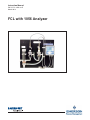
Emerson FCL with 1050 Analyzer 1056 User manual
- Category
- Measuring, testing & control
- Type
- User manual
This manual is also suitable for

FCL with 1056 Analyzer
Instruction Manual
PN 51-FCL-1056 rev.E
March 2012

ESSENTIAL INSTRUCTIONS
READ THIS PAGE BEFORE PROCEEDING!
Your purchase from Rosemount Analytical, Inc. has
resulted in one of the finest instruments available for
your particular application. These instruments have
been designed, and tested to meet many national
and international standards. Experience indicates
that its performance is directly related to the quality
of the installation and knowledge of the user in oper-
ating and maintaining the instrument. To ensure
their continued operation to the design specifica-
tions, personnel should read this manual thoroughly
before proceeding with installation, commissioning,
operation, and maintenance of this instrument. If
this equipment is used in a manner not specified by
the manufacturer, the protection provided by it
against hazards may be impaired.
• Failure to follow the proper instructions may
cause any one of the following situations to
occur: Loss of life; personal injury; property dam-
age; damage to this instrument; and warranty
invalidation.
• Ensure that you have received the correct model
and options from your purchase order. Verify that
this manual covers your model and options. If
not, call 1-800-854-8257 or 949-757-8500 to
request correct manual.
• For clarification of instructions, contact your
Rosemount representative.
• Follow all warnings, cautions, and instructions
marked on and supplied with the product.
• Use only qualified personnel to install, operate,
update, program and maintain the product.
• Educate your personnel in the proper installation,
operation, and maintenance of the product.
• Install equipment as specified in the Installation
section of this manual. Follow appropriate local
and national codes. Only connect the product to
electrical and pressure sources specified in this
manual.
• Use only factory documented components for
repair. Tampering or unauthorized substitution of
parts and procedures can affect the performance
and cause unsafe operation of your process.
• All equipment doors must be closed and protec-
tive covers must be in place unless qualified per-
sonnel are performing maintenance.
• If this equipment is used in a manner not speci-
fied by the manufacturer, the protection provided
by it against hazards may be impaired.
Equipment protected throughout by double insulation.
• Installation of cable connections and servicing of this product
require access to shock hazard voltage levels.
• Main power and relay contacts wired to separate power
source must be disconnected before servicing.
• Do not operate or energize instrument with case open!
• Signal wiring connected in this box must be rated at least
240 V.
• Non-metallic cable strain reliefs do not provide grounding
between conduit connections! Use grounding type bushings
and jumper wires.
• Unused cable conduit entries must be securely sealed by
non-flammable closures to provide enclosure integrity in
compliance with personal safety and environmental protection
requirements. Unused conduit openings must be sealed with
NEMA 4X or IP65 conduit plugs to maintain the ingress
protection rating (NEMA 4X).
• Electrical installation must be in accordance with the National
Electrical Code (ANSI/NFPA-70) and/or any other applicable
national or local codes.
• Operate only with front and rear panels fastened and in place
over terminal area.
• Safety and performance require that this instrument be
connected and properly grounded through a three-wire
power source.
• Proper relay use and configuration is the responsibility of the
user.
Emerson Process Management
2400 Barranca Parkway
Irvine, CA 92606 USA
Tel: (949) 757-8500
Fax: (949) 474-7250
http://www.rosemountanalytical.com
© Rosemount Analytical Inc. 2012
CAUTION
WARNING
This product is not intended for use in the light industrial,
residential or commercial environments per the instrument’s
certification to EN50081-2.
This product generates, uses, and can radiate radio frequency
energy and thus can cause radio communication interference.
Improper installation, or operation, may increase such interfer-
ence. As temporarily permitted by regulation, this unit has not
been tested for compliance within the limits of Class A comput-
ing devices, pursuant to Subpart J of Part 15, of FCC Rules,
which are designed to provide reasonable protection against
such interference. Operation of this equipment in a residential
area may cause interference, in which case the user at his own
expense, will be required to take whatever measures may be
required to correct the interference.
WARNING
RISK OF ELECTRICAL SHOCK

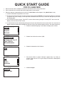
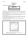
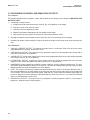
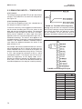
QUICK START GUIDE
FOR FCL ANALYZER
1. Refer to Section 2.0 for installation instructions and Section 3.0 for wiring instructions.
2. Once connections are secured and verified, apply power to the analyzer.
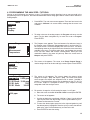
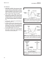
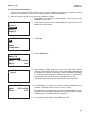
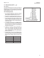
3. When the analyzer is powered up for the first time, Quick Start screens appear. Using Quick Start is easy.
a. A backlit field shows the position of the cursor.
b. To move the cursor left or right, use the keys to the left or right of the ENTER key. To scroll up or down or to increase
or decrease the value of a digit, use the keys above and below the ENTER key. Use the left and right keys to move
the decimal point.
c. Press ENTER to store a setting. Press EXIT to leave without storing changes. Pressing EXIT also returns the
display to the initial Quick Start screen.
d. A vertical black bar with a downward pointing arrow on the right side of the screen means there are more items to
display. Continue scrolling down to display all the items. When you reach the bottom of the list, the arrow will point up.
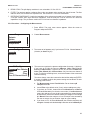
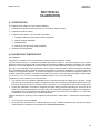
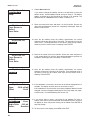
4. Choose the desired language. Scroll down to display more choices.
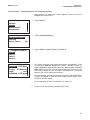
5. Choose free chlorine for sensor 1 (S1).
6. Choose the desired units for chlorine.
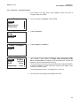
7. The screens shown in steps 7 through 9 appear only if you have an
FCL-02. If you have an FCL-01, go to step 10. Otherwise, choose pH for
sensor 2 (S2).
8. Choose Analyzer.
Language
Francais
Espanol
Deutsch
English
S1 Measurement
pH Independ. Free Cl
Total Chlorine
Monochloramine
Free Chlorine
Units
mg/L
ppm
S2 Measurement
ORP
Redox
Ammonia
pH
S2 Preamp
Analyzer
Sensor/J Box
Analyzer

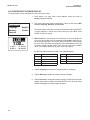
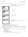
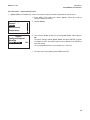
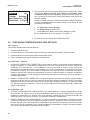
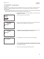
12. The main display appears. The outputs and alarms (if an alarm board is present) are assigned to default values.
13. To change outputs, alarms, and other settings go to the main menu and choose Program. Follow the prompts. A
menu tree is on the following two pages. To calibrate the sensor(s) refer to section 6.0.
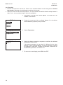
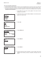
Temp Units
o
C
o
F
S1 Manual pH
7.00
0
S1 Free Cl
pH Correction
Manual
Live/Continous
Live/Continous
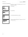
9. Choose Live/Continuous. Go to step 11.
10. The screen shown at left appears only if you have an FCL-01. Enter the
pH of the process liquid.
11. Choose the desired temperature units.

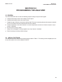
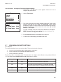
MENU TREE
Calibrate
Sensor 1 (Free chlorine)
Chlorine
Zero
In process
Temperature
Sensor 2 (pH)
pH
Buffer Cal
Auto
Select buffer (NIST, DIN19267, Ingold, Merck, or Fisher)
Select stability criteria
Manual
Standardize
Enter slope or offset
Temperature
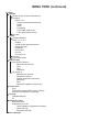
Output 1
Output 2
Hold
Sensor 1
Sensor 2
Display
Main format configuration
Language selection
Warning (enable or disable)
Screen contrast
See next page for rest of menu tree

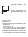
Program
Outputs
Range (assign values to 4 and 20 mA)
Configure
Output 1 or 2
Assign sensor and measurement
Range
Scale
Dampening
Fault mode (fixed or live)
Fault value (output current)
Simulate
Alarms
Configure/Setpoint
Alarm 1, 2, 3, or 4
Setpoint
Assign sensor and measurement
High or low logic
Deadband
Interval time
On time
Recovery time
Simulate
Synchronize timers
Measurement
Free chlorine (sensor 1)
Measurement selection
Units
Filter
Resolution
pH (sensor 2)
Measurement selection
Preamplifier location
Solution temperature correction
Resolution
Filter
Reference impedance (high or low)
Temperature
Units
Temperature compensation (auto or manual)
Set manual temperature (if selected)
Security
Calibrate/Hold only
All
Diagnostic Setup
Reference Offset
Diagnostics (on or off)
Glass impedance temperature correction
Glass fault high
Reference fault high
Reset Analyzer
MENU TREE (continued)

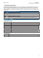
About This Document
This manual contains instructions for installation and operation of the Model FCL-1056
The following list provides notes concerning all revisions of this document.
Rev. Level
Date Notes
A9 /08 This is the initial release of the product manual. The manual has been
reformatted to reflect the Emerson documentation style and updated to
reflect any changes in the product offering.
B11 /09 Minor changes to manual.
C 10 /10 Updated DNV logo and copyright date.
D4 /11 Updated cover photo, added Model 3900 pH sensor wiring diagrams (blue
and gray cables), corrected flow cell part numbers, added removing trapped
bubbles information to troubleshooting section.
E 03/12 Update addresses - mail and web.

i
MODEL FCL-1056 TABLE OF CONTENTS
FCL-1056
TABLE OF CONTENTS
Section Title Page
1.0 DESCRIPTION AND SPECIFICATIONS ................................................................ 1
1.1 Applications ............................................................................................................. 1
1.2 Features................................................................................................................... 1
1.3 Specifications - General ........................................................................................... 2
1.4 Specifications - Sensor ............................................................................................ 2
1.5 Specifications - Analyzer.......................................................................................... 2
1.6 Ordering Information ................................................................................................ 3
2.0 INSTALLATION ....................................................................................................... 5
2.1 Unpacking and Inspection........................................................................................ 5
2.2 Installation................................................................................................................ 6
3.0 WIRING.................................................................................................................... 9
3.1 Power, Alarm, and Output Wiring............................................................................. 9
3.2 Sensor Wiring ......................................................................................................... 10
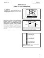
4.0 DISPLAY AND OPERATION ................................................................................... 13
4.1 Display ..................................................................................................................... 13
4.2 Keypad..................................................................................................................... 14
4.3 Programming the Analyzer - Tutorial........................................................................ 15
4.4 Security .................................................................................................................... 16
4.5 Using Hold ............................................................................................................... 17
4.6 Configuring the Main Display ................................................................................... 18
5.0 PROGRAMMING THE ANALYZER ........................................................................ 19
5.1 General .................................................................................................................... 19
5.2 Default Settings........................................................................................................ 19
5.3 Configuring, Ranging and Simulating Outputs......................................................... 22
5.4 Configuring Alarms and Assigning Setpoints ........................................................... 25
5.5 Configuring the Measurement.................................................................................. 30
5.6 Configuring Temperature Related Settings .............................................................. 32
5.7 Configuring Security Settings................................................................................... 33
5.8 Setting up Diagnostics ............................................................................................. 34
5.9 Resetting the Analyzer ............................................................................................. 36
6.0 CALIBRATION ........................................................................................................ 37
6.1 Introduction .............................................................................................................. 37
6.2 Calibrating Temperature........................................................................................... 37
6.3 Calibration - Free Chlorine ...................................................................................... 39
6.4 Calibration - pH ....................................................................................................... 42
6.5 Calibration - Analog Outputs .................................................................................... 49

Section Title Page
7.0 DIGITAL COMMUNICATIONS ............................................................................... 51
8.0 MAINTENANCE ...................................................................................................... 53
8.1 Analyzer ................................................................................................................... 53
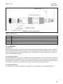
8.2 Chlorine Sensor ....................................................................................................... 54
8.3 pH Sensor ................................................................................................................ 55
8.4 Constant Head Flow Controller................................................................................ 56
9.0 TROUBLESHOOTING ........................................................................................... 59
9.1 Overview .................................................................................................................. 59
9.2 Using the Diagnostic Feature................................................................................... 59
9.3 Troubleshooting When a Fault Message is Showing .............................................. 60
9.4 Troubleshooting When a Warning Message is Showing.......................................... 63
9.5 Troubleshooting When No Error Message is showing - Chlorine ............................ 64
9.6 Troubleshooting When No Error Message is showing - pH ..................................... 67
9.7 Troubleshooting When No Error Message is showing - General ............................. 70
9.8 Simulating Inputs - Chlorine..................................................................................... 70
9.9 Simulating Inputs - pH.............................................................................................. 71
9.10 Simulating Inputs Temperature ................................................................................ 72
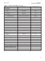
LIST OF TABLES
Number Title Page
1.6 Ordering Information ............................................................................................... 3
1.6 Component Parts ..................................................................................................... 3
1.6 Accessories .............................................................................................................. 3
3.2 Sensor Wiring........................................................................................................... 10
4.6 Display Abbreviations ............................................................................................... 18
5.1 Default Settings ........................................................................................................ 20
5.1 Default Settings cont ................................................................................................ 21
5.7 Configuring Security Settings ................................................................................... 33
5.8.2 Procedure - Setting Up Diagnostics ......................................................................... 35
6.4.2 Calibration - pH ........................................................................................................ 42
8.1 Analyzer ................................................................................................................... 53
8.2.1 Spare Parts .............................................................................................................. 55
8-3 Replacement Parts for Constant Head Flow Controller Assembly (Model FCL-01).
................................................................................................................................57
8-3 Replacement Parts for Constant Head Flow Controller Assembly (Model FCL-02).
................................................................................................................................58
9.3 Troubleshooting When a Fault Message is Showing ............................................... 60
9.4 Troubleshooting When a Warning Message is Showing .......................................... 63
9.5 Troubleshooting When No Error Message is Showing - Chlorine ............................ 64
9.6 Troubleshooting When No Error Message is Showing - pH ..................................... 67
MODEL FCL-1056 TABLE OF CONTENTS
TABLE OF CONTENTS CONT’D
ii

LIST OF FIGURES
Number Title Page
2-1 Model FCL-01 .................................................................................................... 7
2-2 Model FCL-02 .................................................................................................... 7
3-1 Analog Output Connections .................................................................................... 9
3-2 Alarm Relay Connections......................................................................................... 10
3-3 Wiring Diagram for Free Chlorine Sensor ................................................................ 11
3-4 Wiring Diagram for 399VP-09 pH Sensor ............................................................... 11
3-5 Wiring Diagram for 3900VP-10 pH Sensor (gray cable) ......................................... 11
3-6 Wiring Diagram for 3900VP-10 pH Sensor (blue cable) .......................................... 11
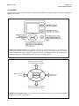
4-1 Main Display............................................................................................................. 13
4-2 Programming Screen Showing Item List .................................................................. 13
4-3 Arrow Bar ................................................................................................................. 13
4-4 Analyzer Keypad ...................................................................................................... 14
4-5 Navigation Keys ....................................................................................................... 14
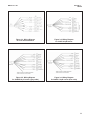
5-1 High Alarm Logic ..................................................................................................... 26
5-2 Low Alarm Logic ...................................................................................................... 26
5-3 Operation of the Interval Timer................................................................................. 26
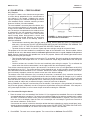
6-1 Sensor Current as a Function of Free Chlorine Concentration ................................ 39
6-2 Calibration Slope and Offset .................................................................................... 42
8-1 Chlorine Sensor Parts .............................................................................................. 55
8-2 Replacement Parts for the Flow Controller Assembly used in Model FCL-01.......... 57
8-3 Replacement Parts for the Flow Controller Assembly used in Model FCL-02.......... 58
9-1 Pin Out Diagram for Model 499ACL-01-VP Sensor ................................................ 61
9-2 Pin Out Diagram for Model 3900VP Sensor............................................................. 61
9-3 Simulating Chlorine .................................................................................................. 70
9-4 Simulating pH Inputs ................................................................................................ 71
9-5 Three-Wire RTD Configuration................................................................................. 72
9-6 Simulating RTD Inputs.............................................................................................. 72
MODEL FCL-1056 TABLE OF CONTENTS
LIST OF TABLES CONT’D
9.6.1 Calibration Error During Two-Point Calibration ........................................................ 67
9.7 Troubleshooting When No Error Message is Showing - General............................. 70
9.9.2 Simulating pH Input .................................................................................................. 71
9.10 Simulating Inputs Temperature................................................................................. 72
iii

Model FCL-1056 SECTION 1.0
DESCRIPTION AND SPECIFICATIONS
SECTION 1.0.
DESCRIPTION AND SPECIFICATIONS
1
1.1 APPLICATIONS
The FCL free chlorine system is intended for the deter-
mination of free chlorine in fresh water. Unlike free
chlorine analyzers from other manufacturers, the FCL
does not use expensive sample conditioning systems
or messy reagents to control pH. Instead, the analyzer
automatically compensates for changes in the pH of
the sample. The FCL is not intended for the determi-
nation of total chlorine or combined chlorine (like
monochloramine). Nor, can the FCL be used for the
determination of chlorine in seawater.
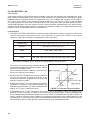
1.2 FEATURES
The FCL uses a membrane-covered amperometric sen-
sor. A polarizing voltage applied to a platinum cathode
behind the membrane reduces the chlorine diffusing
through the membrane and keeps the concentration of
chlorine in the sensor equal to zero. The current gen-
erated by the cathode reaction is proportional to the
rate of diffusion of chlorine through the membrane.
Because the concentration of chlorine in the sensor is
zero, the diffusion rate and the current are proportion-
al to the concentration of chlorine in
the sample.
All amperometric free chlorine sensors respond to
changes in pH. Although free chlorine is a mixture of
hypochlorous acid and hypochlorite ion, hypochlorous
acid alone is responsible for the sensor current.
Because the relative amounts of hypochlorous acid
and hypochlorite ion depend on pH, a pH change will
cause the current and the apparent free chlorine con-
centration to change, even though the true concentra-
tion remained constant. Most manufacturers solve the
pH-dependence problem by treating the sample with
acid, which lowers the pH and converts hypochlorite
ion into hypochlorous acid. The Model FCL avoids the
expense and inconvenience of sample conditioning by
measuring the pH and applying a correction to the
raw chlorine sensor signal. The correction is valid
between pH 6.0 and 9.5. For samples having pH
between 9.5 and 10.0, consult the factory.
The Model FCL is available in two options: Model
FCL-01 with manual pH correction and Model FCL-02
with continuous pH correction. Choose the FCL-01
if the pH varies less than 0.2 or if pH changes are
predictable or seasonal. Choose the FCL-02 if the
pH varies more than 0.2. To provide the continuous pH
correction, the Model FCL-02 requires a separate
pH sensor.
Maintenance is fast and easy. Replacing a membrane
requires no special tools or fixtures. A screw cap holds
the pre-tensioned membrane in place. Replacing the
electrolyte solution takes only minutes.
The FCL includes the easy-to-use Model 1056 analyz-
er. The analyzer features two fully programmable 4-20
mA outputs and four fully programmable relays. The
back-lit, four line display allows the user to read sam-
ple pH and chlorine concentration at a glance.
Valves, rotameters, and pressure regulators to control
sample flow are things of the past with the Model FCL.
A constant head overflow sampler ensures the correct
sample flow to each sensor. To eliminate wiring
hassles, quick-disconnect Variopol cable is standard.
Stable free chlorine standards do not exist. The chlorine
sensor must be calibrated using the results of a labo-
ratory test run on a grab sample.
• COMPLETE SYSTEM INCLUDES sensor, connecting cable, analyzer, and flow controller
• CONTINUOUS pH CORRECTION eliminates expensive and messy reagents and trouble-
some sample conditioning systems
• MEASURES FREE CHLORINE IN SAMPLES having pH as high as 9.5
1
• VARIOPOL QUICK-DISCONNECT FITTINGS make replacing sensors easy
• FEATURE-PACKED ANALYZER: dual outputs, four fully-programmable alarm relays, and
large four line display
1
In some cases, the sensor can be used in samples having pH as great as 10.0. Consult the factory.

1.3 SPECIFICATIONS — GENERAL
Sample requirements:
Pressure: 3 to 65 psig (122 to 549 kPa abs)
A check valve in the inlet prevents the sensor
flow cells from going dry if sample flow is lost.
The check valve opens at 3 psig (122 kPa abs).
If the check valve is removed, minimum pres-
sure is 1 psig (108 kpa abs).
Temperature: 32 to 122°F (0 to 50°)
Minimum Flow: 3 gal/hr (11 L/hr)
Maximum flow: 80 gal/hr (303 L/hr); high flow
causes the overflow tube to back up
Sample Conductivity: >50 µS/cm at 25°C
Process connection: 1/4-in OD tubing compression
fitting (can be removed and replaced with barbed
fitting for soft tubing)
Drain connection: 3/4-in barbed fitting. Sample must
drain to open atmosphere
Wetted parts:
Overflow sampler and flow cell: acrylic, polycar-
bonate, Kynar
®1
, nylon, silicone
Chlorine sensor: Noryl
®2
, Viton
®3
, wood, silicone,
polyethersulfone, polyester, and platinum
pH sensor (3900VP) : Stainless steel, glass,
Teflon
®4
, polyphenylene sulfide, EPDM, and
silicone
Response time to step change in chlorine concen-
tration: <80 sec to 95% of final reading for inlet
sample flow of 3 gph (11 L/hr)
Weight/shipping weight:
Model FCL-01: 10 lb/13 lb (4.5 kg/6.0 kg)
Model FCL-02: 11 lb/14 lb (5.0 kg/6.5 kg)
[rounded to the nearest 1 lb. (0.5 kg)]
1.4 SPECIFICATIONS — SENSOR
Free chlorine range: 0 to 10 ppm as Cl
2
. For higher
ranges, consult the factory.
pH correction range: 6.0 to 9.5. For samples having
pH between 9.5 and 10.0, consult the factory. If
pH < 6.0, correction is not necessary. For manual
pH correction, choose option -01. For continuous
pH correction choose option -02.
Accuracy: Accuracy depends on the accuracy of the
chemical test used to calibrate the sensor.
Interferences: Monochloramine, permangante,
peroxides.
Electrolyte volume: 25 mL (approx.)
Electrolyte life: 3 months (approx.); for best results
replace electrolyte monthly.
1.5 SPECIFICATIONS — ANALYZER
Case: Polycarbonate, NEMA 4X/CSA4 (IP65)
Display: Monochromatic back-lit LCD. Main character
height 0.6 in (15 mm). Display is user-programable.
Languages: English, German, Italian, Spanish,
French, Portuguese
Ambient temperature and humidity: 32 to 131°F
(0 to 55°C); RH 5 to 95% (con-condensing)
Storage temperature: -4 to 140°F (-20°C and 60°C)
Power: 84 to 265 Vac, 47.5-65.0 Hz, 15 W.
Equipment protected by double insulation.
RFI/EMI: EN-61326
LVD: EN-61010-1
Outputs: Two 4-20 mA or 0-20 mA isolated outputs.
Continuously adjustable. Linear or logarithmic.
Maximum load 550 ohms. Output dampening with
time constant of 5 sec is user-selectable.
Alarms: Four alarm relays. Any relay can be configured
as a fault alarm instead of a process alarm. Each
relay can be configured independently and each can
be programmed with interval timer settings.
Relays: Form C, SPDT, epoxy sealed
Relay Contact ratings:
5 A at 28 VDC or 300 VAC (resistive)
1/8 HP at 120/240 VAC.
Terminal Connections Rating: Power connector
(3-leads): 18-12 AWG wire size. Current output
connectors (2-leads): 24-16 AWG wire size. Alarm
relay terminal blocks: 18-16 AWG wire size
2
MODEL FCL-1056 SECTION 1.0
DESCRIPTION AND SPECIFICATIONS
1
Kynar is a registered trademark of Elf Atochem North America.
2
Noryl is a registered trademark of General Electric.
3
Viton is a registered trademark of E.I. duPont de Nemours & Co.
4
Teflon is a registered trademark of E.I. duPont de Nemours & Co.

3
1.6 ORDERING INFORMATION
FCL Free Chlorine Measuring System. The FCL is a complete system for the determination of free chlorine in
aqueous samples. It consists of the sensor(s), analyzer, and constant head overflow device to control sample
flow. All components are mounted on a backplate. Model option -02 includes a pH sensor for continuous, auto-
matic pH correction. Three replacement membranes and a 4-oz. bottle of electrolyte solution are shipped with the
chlorine sensor.
ACCESSORIES
PART # DESCRIPTION
9240048-00 Tag, stainless steel (specify marking)
COMPONENT PARTS
ANALYZER MODEL DESCRIPTION
1056-03-24-38-AN 1056-03-24-38-AN, 115/230 Vac 50/60 Hz, alarm relays, analog outputs, chlorine only
1056-03-24-32-AN 1056-03-24-32-AN, 115/230 Vac 50/60 Hz, alarm relays, analog outputs, chlorine and pH
CODE pH CORRECTION (required selection)
01 Without pH sensor
02 With pH sensor
CODE pH CORRECTION (required selection)
220
1056-03-24-38-AN, 115/230 Vac 50/60 Hz, alarm relays, analog outputs, chlorine only (option -01 only)
221
1056-03-24-32-AN, 115/230 Vac 50/60 Hz, alarm relays, analog outputs, chlorine and pH (option -02 only)
FCL FREE CHLORINE MEASURING SYSTEM
FCL-02 -221 EXAMPLE
MODEL FCL-1056 SECTION 1.0
DESCRIPTION AND SPECIFICATIONS
SENSOR MODEL DESCRIPTION
499ACL-01-54-VP Free chlorine sensor with Variopol connector
3900VP-02-10 pH sensor with Variopol connector
SENSOR CABLE DESCRIPTION
23747-04 Interconnecting cable, Variopol for 499ACL sensor, 4 ft
23645-08 Interconnecting cable, Variopol for 3900VP sensor, 4 ft

This page left blank intentionally
4
MODEL FCL-1056 SECTION 1.0
DESCRIPTION AND SPECIFICATIONS

5
SECTION 2.0.
INSTALLATION
MODEL FCL-1056 SECTION 2.0
INSTALLATION
2.1 UNPACKING AND INSPECTION
Inspect the shipping container. If it is damaged, contact the shipper immediately for instructions. Save the box. If
there is no apparent damage, unpack the container. Be sure all items shown on the packing list are present. If
items are missing, notify Rosemount Analytical immediately.
2.1.1 FCL-01 (free chlorine without continuous pH correction)
Model FCL-01 consists of the following items mounted on a back plate.
1. Model 1056-03-24-38-AN analyzer with sensor cable attached.
2. Constant head overflow sampler with flow cell for chlorine sensor.
The free chlorine sensor (Model 499ACL-01-54-VP), three membrane assemblies, and a bottle of electrolyte
solution are in a separate package.
2.1.2 FCL-02 (free chlorine with continuous pH correction)
Model FCL-02 consists of the following items mounted on a back plate.
1. Model 1056-03-24-32-AN analyzer with sensor cables attached.
2. Constant head overflow sampler with flow cells for pH and chlorine sensors.
3. Stand to hold pH buffer solution during calibration.
The free chlorine sensor (Model 499ACL-01-54-VP), shipped with three membrane assemblies and a bottle of
electrolyte solution, and the Model 3900VP-02-10 pH sensor, which replaces the older Model 399VP-09 sensor,
are in separate packages.

6
MODEL FCL-1056 SECTION 2.0
INSTALLATION
2.2 INSTALLATION
2.2.1 General Information
1. Although the system is suitable for outdoor use, do not install it in direct sunlight or in areas of extreme
temperature.
2. To keep the analyzer enclosure watertight, install plugs (provided) in the unused cable openings.
3. Install the system in an area where vibrations and electromagnetic and radio frequency interference are
minimized or absent.
4. Be sure there is easy access to the analyzer and sensors.
2.2.2 Sample Requirements
Be sure the sample meets the following requirements:
1. Temperature: 32 to 122ºF (0 to 50ºC)
2. Pressure: 3 to 65 psig (122 to 549 kPa abs)
3. Minimum flow: 3 gal/hr (11 L/hr)
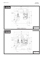
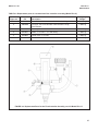
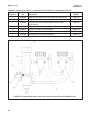
2.2.3 Mounting, Inlet, and Drain Connections
The FCL is intended for wall mounting only. Refer to Figure 2-1 or 2-2 for details. The sensor(s) screw into the flow
cell adapters as shown in the figures. For Model FCL-02 (free chlorine with continuous pH adjustment), the pH
sensor must be installed as shown in Figure 2-2.
A 1/4-inch OD tubing compression fitting is provided for the sample inlet. If desired, the compression fitting can
be removed and replaced with a barbed fitting. The fitting screws into a 1/4-inch FNPT check valve. The check
valve prevents the sensor flow cells from going dry if sample flow is lost.
The sample drains through a 3/4-inch barbed fitting. Attach a piece of soft tubing to the fitting and allow the waste
to drain open atmosphere. Do not restrict the drain line.
Adjust the sample flow until the water level is even with the central overflow tube and excess water is flowing down
the tube.
2.2.4 Electrical Connections
Refer to Section 3.1 for details.
2.2.5 Installing the Sensor(s)
The FCL is provided with sensor cables pre-wired to the analyzer. Connect the chlorine sensor (Model 499ACL-
01-54-VP) to the cable labeled CL. Connect the pH sensor (Model 3900VP-02-10 or older Model 399VP-09) to the
cable labeled pH. The terminal end of the sensor is keyed to ensure proper mating with the cable receptacle. Once
the key has slid into the mating slot, tighten the connection by turning the knurled ring clockwise.
The sensor(s) screw into the plastic fitting(s), which are held in the flow cell(s) by the union nut. Do not remove the
protective cap on the sensor(s) until ready to put the sensor(s) in service.
CAUTION
The FCL free chlorine system is NOT suitable for use
in hazardous areas.

7
FIGURE 2-1. Model FCL-01
FIGURE 2-2. Model FCL-02
INCH
MILLIMETER
INCH
MILLIMETER
MODEL FCL-1056 SECTION 2.0
INSTALLATION

This page left blank intentionally
8
MODEL FCL-1056 SECTION 2.0
INSTALLATION

SECTION 3.0.
WIRING
MODEL FCL-1056 SECTION 3.0
WIRING
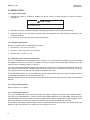
3.1 POWER, ALARM, AND OUTPUT WIRING
3.1.1 Power
Wire AC mains power to the power supply board, which is mounted vertically on the left hand side of the analyz-
er enclosure. The power connector is at the top of the board. Unplug the connector from the board and wire the
power cable to it. Lead connections are marked on the connector. (L is live or hot; N is neutral, the ground con-
nection has the standard symbol.)
AC power wiring should be 14 gauge or greater. Run the power wiring through the conduit opening nearest the
power terminal. Provide a switch or breaker to disconnect the analyzer from the main power supply. Install the
switch or breaker near the analyzer and label it as the disconnecting device for the analyzer.
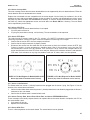
3.1.2 Analog output wiring
Two analog current outputs are located on the main circuit board, which is attached to the inside of the enclosure
door. Figure 3-1 shows the location of the terminals. The connectors can be detached for wiring. TB-1 is output 1.
TB-2 is output 2. Polarity is marked on the circuit board.
For best EMI/RFI protection, use shielded output signal cable enclosed in earth-grounded metal conduit.
Keep output signal wiring separate from power wiring. Do not run signal and power or relay wiring in the same
conduit or close together in a cable tray.
FIGURE 3-1. Analog output connections. The analog outputs are on the main
board near the hinged end of the enclosure door.
9
Electrical installation must be in accordance with
the National Electrical Code (ANSI/NFPA-70)
and/or any other applicable national or local codes.
WARNING
RISK OF ELECTRICAL SHOCK

MODEL FCL-1056 SECTION 3.0
WIRING
3.2 SENSOR WIRING
The Model FCL is provided with sensor cables pre-wired to the analyzer. If it is necessary to replace the sensor
cable, refer to the instructions below.
1. Shut off power to the analyzer.
2. Loosen the four screws holding the front panel in place and let it drop down.
3. Locate the appropriate signal board.
4. Loosen the gland fitting and carefully push the sensor cable up through the fitting as you pull the board
forward to gain access to the wires and terminal screws. Disconnect the wires and remove the cable.
5. Insert the new cable through the gland and pull the cable through the cable slot.
6. Wire the sensor to the signal board. Refer to the wiring diagrams in Figures 3-3 and 3-4.
7. Once the cable has been connected to the board, slide the board fully into the enclosure while taking up the
excess cable through the cable gland. Tighten the gland nut to secure the cable and ensure a sealed enclosure.
Slot 1 (left) Slot 2 (center) Slot 3 (right)
communication input 1 (chlorine) input 2 (pH)
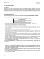
3.1.3 Alarm wiring.
The alarm relay terminal strip is located just below the
power connector on the power supply board. See
Figure 3-2.
Keep alarm relay wiring separate from signal wiring.
Do not run signal and power or relay wiring in the
same conduit or close together in a cable tray.
FIGURE 3-2. Alarm relay connections.
10
WARNING
Exposure to some chemicals may degrade the sealing
properties used in the following devices: Zettler
Relays (K1-K4) PN AZ8-1CH12DSEA
Page is loading ...
Page is loading ...
Page is loading ...
Page is loading ...
Page is loading ...
Page is loading ...
Page is loading ...
Page is loading ...
Page is loading ...
Page is loading ...
Page is loading ...
Page is loading ...
Page is loading ...
Page is loading ...
Page is loading ...
Page is loading ...
Page is loading ...
Page is loading ...
Page is loading ...
Page is loading ...
Page is loading ...
Page is loading ...
Page is loading ...
Page is loading ...
Page is loading ...
Page is loading ...
Page is loading ...
Page is loading ...
Page is loading ...
Page is loading ...
Page is loading ...
Page is loading ...
Page is loading ...
Page is loading ...
Page is loading ...
Page is loading ...
Page is loading ...
Page is loading ...
Page is loading ...
Page is loading ...
Page is loading ...
Page is loading ...
Page is loading ...
Page is loading ...
Page is loading ...
Page is loading ...
Page is loading ...
Page is loading ...
Page is loading ...
Page is loading ...
Page is loading ...
Page is loading ...
Page is loading ...
Page is loading ...
Page is loading ...
Page is loading ...
Page is loading ...
Page is loading ...
Page is loading ...
Page is loading ...
Page is loading ...
Page is loading ...
Page is loading ...
Page is loading ...
Page is loading ...
Page is loading ...
-
 1
1
-
 2
2
-
 3
3
-
 4
4
-
 5
5
-
 6
6
-
 7
7
-
 8
8
-
 9
9
-
 10
10
-
 11
11
-
 12
12
-
 13
13
-
 14
14
-
 15
15
-
 16
16
-
 17
17
-
 18
18
-
 19
19
-
 20
20
-
 21
21
-
 22
22
-
 23
23
-
 24
24
-
 25
25
-
 26
26
-
 27
27
-
 28
28
-
 29
29
-
 30
30
-
 31
31
-
 32
32
-
 33
33
-
 34
34
-
 35
35
-
 36
36
-
 37
37
-
 38
38
-
 39
39
-
 40
40
-
 41
41
-
 42
42
-
 43
43
-
 44
44
-
 45
45
-
 46
46
-
 47
47
-
 48
48
-
 49
49
-
 50
50
-
 51
51
-
 52
52
-
 53
53
-
 54
54
-
 55
55
-
 56
56
-
 57
57
-
 58
58
-
 59
59
-
 60
60
-
 61
61
-
 62
62
-
 63
63
-
 64
64
-
 65
65
-
 66
66
-
 67
67
-
 68
68
-
 69
69
-
 70
70
-
 71
71
-
 72
72
-
 73
73
-
 74
74
-
 75
75
-
 76
76
-
 77
77
-
 78
78
-
 79
79
-
 80
80
-
 81
81
-
 82
82
-
 83
83
-
 84
84
-
 85
85
-
 86
86


Emerson FCL with 1050 Analyzer 1056 User manual
- Category
- Measuring, testing & control
- Type
- User manual
- This manual is also suitable for
Ask a question and I''ll find the answer in the document
Finding information in a document is now easier with AI
Related papers
-
Emerson TCL User manual
-
-
Rosemount Solu Comp Xmt-P-FF/FI Owner's manual
-
Rosemount 399VP General Purpose pH Sensor User manual
-
-
-
-
-
-
Other documents
-
 Hach pHD Sensor User manual
-
 Hach Polymetron 9582sc Basic User Manual
-
 Hach pHD Sensor User manual
-
Hach CL17sc User manual
-
 Hach Polymetron 9582sc User manual
-
 Hach CLT10sc User manual
-
 Hach Chlorine Sensor User manual
-
 AND AX-MX-43 User manual
-
 Hach CLT10sc User manual
-
Emerson Process Management 1056 User manual


