Page is loading ...

User and Maintenance Manual
for the Homeowner
and
Installation Instructions
for the Contractor
ACU-STEAM™ Humidier
by Thermolec
Please read this manual carefully before beginning installation.
Important Notice to the Contractor :
Once the installation is complete, please leave this manual with the customer for future reference.
!

CONTRACTOR
1. Warnings and Disclaimer – Installation Precautions
Please read and understand the warnings and instructions fully before you begin this installation and keep
them for future reference.
The manufacturer will assume no responsibility and the warranty will be void if the installer or the user does not
adhere to the following precautions :
1.1 Thishumidierwillbeconnectedtoandusedunderwaterpressureanditmustbeinstalledinsucha
way that if a leak occurs, the water could not cause any damage to the property. Make sure all water
connections are properly installed or a water leak could occur.
1.2 Thishumidierisintendedforuseonforcedwarmaircirculationfurnaces,aswellasmulti-fuel
furnaces, which have, at least, one supply duct connected to the furnace and where a positive air
pressure can be measured.
1.3 Donotinstallahumidierwherethesurroundingtemperaturemaybe32ºF(0ºC)orcolder.Freezing
waterwilldamagethehumidierandmayburstthesupplyline,resultinginpropertydamage.
1.4 Donotinstallthehumidierdirectlyonthefurnacehousing.
1.5 Always check that you are not about to cut or drill into an air conditioning coil or electrical accessory
during installation.
1.6 Donotinstallahumidierifthecitywaterpressureexceeds90psi.Checkthelocalcodesrelatedto
pressure reduction.
1.7 Do not install the steam delivery stub or steam diffuser in the supply duct ifthepressureexceeds0.5”
WaterColumn(0.125kPa).
1.8 Theinstallation,wiringandplumbingofthehumidiermustcomplywithnational,stateandlocal
electrical, plumbing and building codes.
1.9 Electricalwiringandwaterlinesmustnotcomeincontactwithsharpedgesorhotsurfaces.
1.10 Makecertainanappropriatedrainsystemisinstalledandthereisnoresistancetotheowofthe
discharged water.
1.11 Do not set the humidity level higher than that recommended or condensation damage will occur.
1.12 Please beware of sharp edges when you cut into a metal duct.
1.13 Always shut the power off before you start the installation or when doing maintenance. An electric
shockfrom120or240voltscouldcauseseriousinjuryordeath.
1.14 When you perform maintenance, please be careful because the unit can be extremely hot. Always
allow enough time for the unit to cool down.
1.15 Topreventelectricshockorinjuries,neveroperatethehumidierwithoutthecoverastherearehigh
voltage and high temperatur components inside.
1.16 Thishumidierwillonlyworkwithnondemineralizedwater.Themaximumwatersupplytemperatureis
86ºF(30ºC)
HOME OWNER

Page 1
Instructions and User Manual for the Homeowner
2. View of the unit
2.1 Externalviewofthehumidier.Fig. 2a
2.2 Water Tank Top View. Please see Fig.2b.
2.3 Water tank Side View. Please see Fig.2c.
Fig. 2c
Fig. 2b
HOME OWNER

Page 2
3. Startup
3.1 Thestartupofthehumidierisdoneinasfollows:
•PutthemainpowerONattheelectricalpanel.ThegreenpilotlightcomesON.Thehumidieris
ready to work.
• Open the water supply valve.
•Adjusttheknobonthehumidistat.
Note:Thehumidiermayperformaushcyclepriortoproducinghumidity.IftheyellowdrainLEDislitand
the unit appears not to be operating properly, allow the unit at least 15 minutes to begin normal operation. This
is considered normal as the control system ensures that all systems are stable before operation.
Working Principle :
3.2 Unlikeothertypesofhumidierswhichproducehumiditybypassingwarmaironawatercurtain,a
rotatingpadoranothertypeofmedia,thishumidierproduceshumidityfromsteam dispersed directly into the
supply duct.
3.3 Ahumidistat(installedeitheronthewallortheairreturnduct)controlstheunit.Adjustthesetpointof
thehumidistataccordingtoyourneedorcomfort.Pleasereadthenextsectionaboutthehumiditycontrol.
3.4 Whenthehumidistatsensesaneedforhumidity,itstartsthehumidicationprocess.
3.5 Thetankllswithwater.
3.6 Theelectroniccontrolstartsthefaninthefurnacetomovetheairasthehumidierstartsboilingwater
andproducingsteam.Ifthefancannotstart(i.e.thereisnoairmovementtotransportthesteamorinsufcient
airpressure),thehumidierstopsitself.Pleasenotethatitmaytakeafewminutestobringthewatertoaboil.
Thesteamexitsthewatertankthroughthesteamhose,movestothesteamdeliverytubeinstalledinthewarm
airductandisreleasedintotheductwhereitmixeswiththemovingair.
3.7 As water evaporates, the electric valve opens as needed to replenish the water in the tank.
3.8 Whenthehumidityreachesthedesiredlevel,thehumidierstopsproducingsteam.Inorderto
eliminatetheresiduesandkeepthetankascleanaspossible,thehumidieralsodrainsafteracertainnumber
ofboiling/rellcycles.ThisisdeterminedbytheDIPswitchesonthelowerrightcorneroftheelectronic
controlboard.Ifthereisstillademandfromthehumidistatafterdraining,thetankrellsandstartstoproduce
steamagain.Thisprocessispartoftheself-cleaningfeature.
3.9 Whenthehumidistatissatised,thefancontinuestorunforashortperiodoftimeinordertoeliminate
thesteamfromtheductsandtheunitgoestoreadymode,waitingforthenextcallfromthehumidistat.
HOME OWNER

Page 3
4. How to Control the Humidity
4.1 Humidity level and comfort are personal matters but it is generally acknowledged that a Relative
Humidityof35-40%isdesirable.However,youshouldtaketheoutsidetemperatureintoconsiderationbefore
setting the humidity level in order to avoid condensation on the windows.
4.2 IfyouinstalledaComfortSteamhumidistatandanoutdoorsensor,asetpointadjustmentwillbedone
automatically as the outdoor temperature falls. The outdoor sensor reduces the setting of the humidistat
according to the outdoor temperature during cold days without having to set the humidistat knob manually.
It does the opposite during mild days. Please see Fig.4b for the percentage of relative humidity on
theelectronichumidistatlabel.Themiddleofthescalecorrespondstothemiddleofthecomfortzone,
approximately35%RH(RelativeHumidity).
4.3 Ifyouareusingamechanicalorotherhumidistat,theadjustmentaccordingtotheoutsidetemperature
willhavetobedonemanually.Foryourinformation,thefollowingtableshowstherecommendedsettingofthe
humidistat according to the outside temperature. Please see Fig.4a.
.
4.4 No matter which humidistat system you are using, please be aware that the humidity level cannot
adjustquickly.Itmaytakesometimetobuildupthehumiditytoyourcomfortlevel.Dependingonthedryness
of the house, carpets, furniture, drapes and wood will absorb moisture before you can feel the change.
4.5 If the house remains unoccupied during the winter season, set the humidistat to the minimum set point
in order to prevent condensation.
Fig. 4b
!
H U M I D I F I C A T I O N S Y S T E M
COMFORTSTEAM
35
30
20
40
50
Outside Temprature Recommended Setting
-22ºF (-30ºC) 15%
-13ºF (-25ºC) 20%
-4ºF (-20ºC) 25%
+5ºF (-15ºC) 30%
+14ºF (-10ºC) 35%
above
23ºF (-5ºC) 40%
Fig. 4a
HOME OWNER

Page 4
5. Functions of the Electronic Circuit
5.1 Theelectronicboardlocatedinsidetheunitcontrolsallthehumidierfunctions.Thefrontpanelis
equippedwithpilotlightsindicatingthestatusofthehumidier.PleaseseeFig.5a.
Please refer to Article 5.2 for the description of the functions.
Theredpilotlight,whichisawarninglight,caneitherglowallthetimeorashwhenactivated.
Incaseoferror,thehumidierentersstand-bymode.Theashingofthepilotlightsindicateswhicherror
happened.Theerrorrecognitionsequenceisasfollows:
• The green pilot light near the power button blinks once;
•Theredlightashesacertain number of times, this is the error code;
• A pause with no light at all;
• Another blink of the green light, once;
• Anotherseriesofashing of the red light;
• And so on until the condition is reset or service is performed.
•ShuttingthepowerOFFatthebreakerinthemainpanelordepressingthepowerbuttonuntilthe
green light is fully on will reset the error code.
5.2 TheCOMFORTSTEAMhumidistatalsohastwopilotlightstoindicatethecurrentstatus.
The green light is lit when the humidistat is demanding for humidity, thus activating the boiling cycle. The red
lightindicatesawarningandreproducesthesamewarningcodeastheredlightonthehumidiercontrol
panel.Ifevertheredlightislitorashingonthehumidistat,youknowimmediatelythatthehumidierneeds
attention.
Display Status Description
On/Standby
Greenlight OFF Thehumidierhasnopower–BreakerisOFF.
Blinking Thehumidierhaspower,butisinstandbymode.
ON Thehumidierhaspowerandisfunctional.
Whitebutton Presstoputthehumidierinstand-bymode.
The green light is blinking.
Press and keep depressed 3 seconds to power
orresetthehumidier.ThegreenlightisON.
!
On/Standby - Green
Fan
Warning
Steam
Fill
Drain
- White
- Red
- White
- Blue
- Yellow
Fig. 5a
Mode
HOME OWNER

Page 5
Fan
White light ON The fan control is activated.
Warning
Red light ON An abnormal condition occurred.
Please refer to the error code table in Section 7.
Steam
Whitelight ON Thehumidierisheatingwatertoproducesteam.
Filling cycle
Bluelight ON Theelectricwatervalveisopenthusllingthe
humidier.
Draining cycle
Yellowlight ON Thehumidierisindrainingmode.
White button Not active on residential models.
!
HOME OWNER

Page 6
6. What To Do if a Malfunction Occurs
6.1 ShutthemainpowerOFFandrestartthehumidiertoseeiftheerrorcodedisappears.
6.2 If you see a water leak, follow the water supply tube and close the valve installed on the water pipe
locatednearthehumidier.
6.3 Please refer to the error code table to identify the possible cause of the malfunction and the actions that
you can take.
6.4 Shouldtheproblempersist,pleasecallyourservicecompany.Theyarethebestqualiedtohelpyou
quickly.Describetheproblemtothemandmentiontheerrorcodeyouobservedonthefrontpanel.Theymay
helpyousolvetheproblemoverthephone.Ifneeded,theywillxtheproblemthemselvesorcallourtechnical
service.
6.5 Shouldyouattempttolookattheunityourself,pleaseapplyallappropriatesafetymeasures.-Shutthe
mainpowerOFFandwait for the unit to cool before you open it.
7. Description of Error Codes
Number of
ashes of the
red light
Error Description Humidier Status
Actions to be Taken
by the Owner
Reset
OFF
No error The humidier is working ne None
Continuous
ON
There is water in the
pan under the tank.
Risk of overow. Humidier stops
itself.
Turn the main power OFF, then
- Open the unit and check for leaks
- Check the drain tube
- Close the supply valve and call for
service
Automatic Reset when
switching main power ON
again.
1
Problem with the water
level sensors inside the
unit.
Internal problem - Humidier cannot
read the water level properly and
stops itself.
Turn the main power OFF, then call
your service company
Automatic Reset when
switching main power ON
again.
3
Inadequate water
supply.
Humidier cannot ll properly and
stops itself - Heating elements and
supply valve are switched off.
Turn the main power OFF, then
- Check the water supply circuit
- Check if the water supply valve is
open.
- Call your service company
Automatic Reset when
switching main power ON
again.
4
Inadequate drainage.
Humidier cannot drain properly - Risk
of overow - the unit stops itself.
Turn the main power OFF, then
- Close the supply valve
- Call your service company
Automatic Reset when
switching main power ON
again.
5
Not enough air ow or
pressure in the supply
duct.
Humidier stops itself.
Turn the main power OFF, then
- Check the air lter in the furnace.
It may be clogged up
- Call your service company
Automatic Reset when
error conditions disappear.
6
Temperature inside the
tank exceeded the high
temperature limit and
the safety switch has
tripped.
This is a very serious condition.
The humidier stops itself and cannot
restart without service.
Turn the main power OFF, then
- Call your service company
Only the service company
can reset the unit after
checking all functions.
HOME OWNER

Page 7
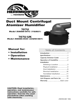
8. Cleaning the tank
As with any device evaporating water, some minerals normally dissolved in the water may create deposits
insideoftheunit.Eventhoughtheunitisdrainingandushingitselfduringnormaloperation,itwillrequirea
bit of maintenance from time to time.
WARNING :
• The water tank and its contents can become extremely hot. Please be careful when you handle it.
• The tank may have water inside.
8.1 Todrainthehumidier,ensurethatthehumidistatiscallingforhumidity(Youmayhavetoadjustthe
setpointhighertomakethishappen),thencyclethemainpowerandtheunitwillenteradraincycle.Itmay
takeafewminutesforthetanktobeginllingasitneedstodotoenvokethesiphondrainingsystem.Once
theunitisdrained,therewillbeapproximatelyoneinchofwaterinthebottomofthetank.Atthistimethemain
power should be turned off and the unit should be allowed to cool.
Wait until the unit has cooled before proceeding with the following steps.
8.2 Beforeproceeding,ensurethemainpowerisOFF.
8.3 Remove the cover by turning the two 1/4 turn screws to the left.
8.4 Unplugthewhitequickconnectwireconnectedonthewaterpanatthebottomoftheunit.Thiswireis
connectedtotheoverowsensor.PleaseseeFig.8a.
White Wire
Main drain Tube
Overflow Pan
1. Lift
2. Pull
Overflow
Drain Tube
Rigid Drain Pipe
Overflow Sensor
Fig. 8a
HOME OWNER

Page 8
8.5 Pull the plastic tube attached to the bottom of the unit out of the rigid drain pipe on the wall. You do not
havetoremovetheplastictubeattachedtothebottomofthepan.Removetheoverowpanfromtheunitby
slightly loosening the front screw then lifting the front of the pan off the screw and pulling it towards you. Please
see Fig.8a. Remove the main drain tube from the rigid drain pipe attached to the wall and check that they are
both clean and clear from deposits.
8.6 Check that the water tank is not too hot to handle. Unfasten the latch around the water tank and remove
thetankfromthemainbodyofthehumidierbypullingitdown.Whenyouremovethetank,itispossibleto
cleantheroundo-ringgasket,butdon’tdiscardit.
NOTE :This round gasket is mandatory and the unit will not work properly without it.
8.7 Soap or vinegar can be used to clean the water tank, the heating element and the tips of the level
sensors. Other cleaning products used to remove scale, lime or calcium are also available on the market, but
DO NOT use a metal brush or any strong acids to clean the tank as they may damage the stainless steel.
8.8 Once completed, reinstall the round gasket around the water tank collar. Please see Fig.8b. Align the
twoarrowslocatedatthefrontofthetankandthexedpartwhileliftingthetankinplace.PleaseseeFig.8c.
Apply even pressure to secure the tank properly in the top part. Then close the latch holding the tank in
position.Verifythattheo-ringgasketandtankareseatedproperly.
Fig. 8b
Fig. 8c
HOME OWNER

Page9
8.9 Puttheoverowpanunderthetankbysittingitbackonitsholdingscrews.
8.10 Reconnectthewhitewireoftheoverowsensoronthewaterpan.
8.11 Puttheoverowandmaindraintubesbackintotherigiddrainpipeattachedtothewall.
8.12 Putthecoverbackonthehumidierandlockitwiththetwoquarter-turnscrews.
8.13 Whennished,turnthemainpowerback“ON”andreadjustthehumidistattoit’sprevioussetpoint.
HOME OWNER

Page10
9. Preventative Maintenance
9.1 Preventivemaintenancetobeperformedeverytwoyears.
In order to avoid problems due to accumulation of deposits, we suggest that you replace the centre metal tube,
thesiliconedraintubeandthelowlevelsensor.Wealsosuggestyoureplacetheroundo-ringgasketaround
thetank.Allthesecomponentsareavailableinatune-upkit.
9.2 TopreparefortheSummerSeason
• Shut the main power OFF
• Shut the water supply valve
• Perform a complete maintenance as described in section 8
• Dry the inside of the tank
HOME OWNER

Page 11
10. Warranty
10.1 Herrmidier,warrantsagainstdefectsinmaterialandworkmanshipthesteamhumidierandallits
componentsfortwo(2)yearsafterdateofshipmentfromitsfactory.
10.2 Anyclaimunderthiswarrantyshallbeconsideredonlyiftheproducthasbeeninstalledandoperatedin
accordance with these written instructions.
10.3 AnymisuseofthesystemoranyrepairbypersonsotherthanthoseauthorizedbyHerrmidier,carried
out without its written consent, voids this warranty.
10.4 Herrmidier’sresponsibilityshallbelimitedinanycasetothereplacementorrepair,initsfactoryorin
theeld,byitsownpersonnelorbyotherschosenbyHerrmidier,atitsoption,ofsuchsteamhumidieror
parts thereof, as shall prove to be defective within the warranty period.
10.5 Herrmidierwillnotbeheldresponsibleforaccidentalorconsequentialdamages,norfordelays,norfor
damagescausedbythereplacementofthesaiddefectivesteamhumidier.
Herrmidier,Inc.
101McNeillRd,
Sanford,NC27330
HOME OWNER

Page 12
Detailed Instructions for the Contractor
11. Unpacking the Unit
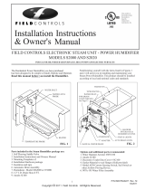
11.1 Contents
Pleaseinspectthecarton’scontentsandreportanymissingpartsordamageimmediately.
1SteamHumidierUnit
1MainDraintube(32”long–alreadyinstalledandcoiledinsidetheunit)
1Steamhose(2feetor4feetlongx1inchI.D.)-dependingonmodel
1Steamdeliverytube(6”L)ordiffuser(12”,15”or19”L,dependingonthehumidiermodel)
1 Instruction and maintenance manual
1 Plastic bag containing installation material and hardware as follows:
2Adjustablehoseclipsforthesteamhose
1Waterhammerabsorber(Redrubberhosewithtwobrassttings)NotsuppliedwithmodelCFS-05B
1Smallbag-KIT#10S
1Watersupplytube(1/4”dia.x7’long)
1OverowDraintubeforthepan(7/16”dia.x24”long)
1Pitottubewithplastictube(5/16”dia.X48”long)
NOTE : The electronic humidistat and the outdoor reset sensor are optional. They may be purchased
separately.Thehumidistatcanbeeitherwalltype(RH)orducttype(DH).
11.2 Water Tank Detailed View. Please see Fig.11a.
Fig. 11a
CONTRACTOR

Page 13
CONTRACTOR
12. Dimensions and Available Models
12.1 Humidierdimensions Fig. 12a
12.2 Available models Fig. 12b
14”
13”
11 5/8”
9”
!
H U M I D I F I C A T I O N S Y S T E M
Capacity
Model Lbs/Hr Power Voltage Current
(Kw) (V) (A)
CFS-05x 4.5 1.5 120 12.5
CFS-10 9.0 3 240/120 12.5
CFS-15 12.0 4 240/120 16.7

CONTRACTOR
Page 14
13. Detailed View and Wiring
View of the top of the unit. Fig. 13a
Green
Yellow
White
Red
Red
Black
Black
Blue
Blue
Heating
Element
Electric
Valve
Steam Outlet
Level
Sensors
High Level
Low Level
Manual
Thermal
Cut-out
Water Pan
White

CONTRACTOR
Page 15
View and list of the wire harness by color and function. Please see Fig.13b & Fig.13c.
FAN
G IN24V
ALARM
H-STAT
A A
Green
Blue
Blue
Red
Red
White
Yellow
Fig 13b
Fan
Relay
Element
Relay
Element
Relay
Transformer
Fuse
Overflow Sensor
connection
On/Standby
Switch
On/Standby LED
Fan LED
Alarm LED
Steam LED
Fill LED
Drain LED
Ground
connection
Neutral
connection
Description of Wire Harness
Color
Function Connected to
Green
Grounds the electronic board to
the tank for the level sensors
Bracketofthehighlimit
cut-out
Blue/Blue
Pair
Powers the electric valve with
24 VDC
ElectricValve
Red/Red
Pair
Overheat signal High-LimitCut-Out
White Reads the low water level LowLevelSensor
Yellow Reads the high water level HighLevelSensor
Fig. 13c

CONTRACTOR
Page 16
Note: Please read sections 14 and 15 before proceeding.
14. Installing the Steam Hose and the Steam Diffuser
14.1 Properinstallationofthesteamdeliverytube/diffuserandsteamhoseiscriticalforthetrouble-
freeoperationofthehumidier.Pleasendanaccessiblelocationontheductandmakesureyouhavea
minimum length of 35”ofstraightductdownstream(withoutelbowsorotherobstructionsonwhichthesteam
couldcondense),toallowthesteamtodisperseeasilyintotheairow.Onceasuitablelocationhasbeenfound
makea11/8”middleinsertionholeinthewarmairductforthesteamdiffuser.Forahorizontalduct,makethe
11/8”holeinthelowerthirdoftheductheight.PleaseseeFig.14a.Foraverticalduct,makethe11/8”holein
the middle of the duct. Please see Fig.14b.
Note:ForHighVelocitysystems,thediffusershouldbeinstalledintheRETURNandnot the warm air duct.
Warning:Beforeinstallinganythingonaduct,alwayscheckthatyouarenotabouttocutordrillintoanair
conditioning coil or electrical accessories.
14.2 Insertthesteamdeliverytube/diffuserinductandalignarrowtopointup.Fastenthesteamdiffuserto
theductusingfour#8x1/2”screwsprovided.inKit#10S.Makesuretheholesonthesteamdiffuser,where
thesteamexitsfrom,arepointingup.PleaseseeFig.14c.
14.3 Install one end of the steam hose onto the steam diffuser using a hose clamp and tighten it.
Fig. 14a HORIZONTAL DUCT
1/3 H
H
Fig. 14b VERTICAL DUCT
W
Air flow
Air flow
W/2
Fig. 14c
UP

CONTRACTOR
Page 17
14.4 Afterinstallingthehumidier(Section15)usethesecondsuppliedhoseclamp,toinstalltheotherend
of the steam hose onto the steam outlet on the top of the water tank and tighten it.
Never try to reduce the diameter of the steam hose or any added rigid piping. It has to be the same as the
diameterofthehumidiertopsteamoutlettting.Thesteammustowwithoutobstruction.
WARNING : Do not let the hose sag when it is connected to the duct. Please see Fig.14d.
Asufcientslopewithno horizontal section is mandatorytoallowanycondensationtoowbacknaturally
to the water tank. Please see Fig.14e. If condensation water accumulates in the hose, the steam will not be
abletoescapenormallythroughthesteamdeliverytube/diffuserandwillleadtoamalfunctionofthehumidier.
Please keep in mind that the hose will soften when heated and will have a tendency to sag.
NOTE : If it is not possible to get enough slope for the condensation to return properly to the water tank, then
anS-shapedsteamtrap(notsupplied)mustbeinstalledatthelowestpointofthesteamhose.Thissteamtrap
hoseshouldhaveaminimumheightof4”.PleaseseeFig.14f.
Warm air duct
Warm air duct
Warm air Duct
WRONG
Fig. 14d
IDEAL
Fig. 14e
Min. 12”
CORRECT
Fig. 14f
Unit must be installed a
minimum of 12” below
the steam delivery tube.
Continuous slope without
sagging is MANDATORY.
Cut hose to the shortest
length possible.

CONTRACTOR
Page 18
15. Installing the Humidier
Foreaseofservice,keepaminimumspaceof24”infrontoftheunit.
15.1 Remove the cover by turning the two 1/4 turn screws to the left and pull the cover towards you.
15.2 Removethewhitewireconnectedonthewaterpanatthebottomoftheunit.Thisistheoverow
sensor.
15.3 Remove the water pan by lifting the front off its holding screw and pull towards you. Do not remove
thosescrewsfromthehumidiermiddlewall.
15.4 Thehumidiermustbeinstalledonaverticalsurface.Becauseofthelengthofthesteamhose
supplied, select the location of the unit as close as possiblewithinamaximumof2feetofthesteamdelivery
tube/diffuser. Please see Fig.15.afornecessaryclearancesaroundthehumidier.
REMINDER :
•Neverinstallthehumidierdirectlyonthefurnacebodyasthiscouldvoidyourfurnacewarranty.
12”
6”
3”
12”
Fig. 15a
/