
7
8
9
4
7
8
9
4
10 10
11 11
12 12
a
b
c
d
e
2
3
4
2
3
8
2
3
4
2
3
8
2
3
4
2
3
8
2
3
4
2
3
8
a
b
(S1)
Torque Blade
Torque Blade
(S5)
(S3)
(S3)
(S3)
(S3)
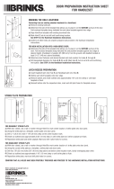
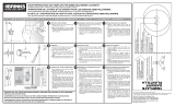
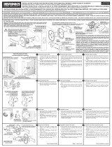
Outside Cylinder Housing
(Style Varies with Series Number)
Keys (2)
Deadbolt Latch
Anti-Pry Shield
Thumbturn Assembly
(S5) Machine Screws (2)
Deadbolt Strike Plate
Square Corner Faceplate
Deadbolt Strike Subplate
(S3) Strike Plate Screws (4)
(S1) Latch Screws (2)
Latch Tail
Latch Faceplate
2-3/8" - or - 2-3/4"
Anti-Pry Shield
Cross-Shape Crank
Outside Cylinder Housing
Torque Blade
Thumbturn Assembly
Thumbturn
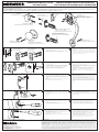
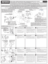
Select Appropriate Faceplate
a. Determine appropriate faceplate design (round or
square corner) to match faceplate cutout in door.
b. If correct faceplate is not already on latch, remove existing
faceplate by separating faceplate from latch and snap on
correct faceplate.
Install Latch
a. Install latch into the hole in the edge of the door in the
"UP" position as marked on the latch with the "cross"
shaped crank at the bottom.
b. Insert two (S1) Latch Screws through the holes in the
faceplate and tighten firmly.
Install Outside Cylinder Housing
a. Place the Anti-Pry shield into the 2-1/8" (54mm) hole
oriented so that it slides over the Deadbolt Latch. The
small diameter of the Anti-Pry Shield fits into a groove
of the Outside Cylinder Housing.
b. Orient the Torque Blade of the cylinder in a horizontal
position. Make sure that the bolt of the Deadbolt Latch
is retracted.
c.
NOTE: If installing into an existing hole that is less than
2-1/8" (54mm) in diameter, you may choose to install without
the Anti-Pry Shield instead of re-drilling the door. Removal of
the Anti-Pry Shield will not affect the function of the deadbolt.
Insert the Torque Blade through the "cross" shaped
crank of the Deadbolt Latch and push the Outside
Cylinder Housing until it is flush with the door, insuring
that the Anti-Pry Shield is seated in its groove.
Install Thumbturn Assembly
a. Orient the Thumbturn in the vertical position and slide
the Thumbturn Assembly onto the torque blade of the
Outside Cylinder and push until it is flush with the
inside of the door.
b. For thinner doors, it may be necessary to shorten the
length of the Torque Blade. To shorten, break the torque
blade at an appropriate pre-notched location on the blade.
c. Insert the two (S5) Machine Screws through the holes in
the Thumbturn Assembly, engaging the holes in the
Outside Cylinder Housing, and tighten firmly.
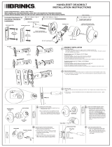
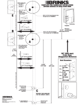
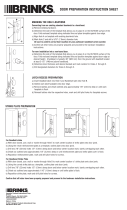
Selecting the Proper Backset
Backset is the distance from door edge to center of hole on
door face. (See Illustration) The latch can be adjusted to fit
either a 2-3/8" (60mm) or a 2-3/4 (70mm) backset. The latch
is set at a 2-3/8" backset from the factory.
To adjust the backset from 2-3/8" to 2-3/4":
a. Retract the latch bolt.
b. Hold the Latch Faceplate in the left hand and the Latch
Tail in the right hand.
c. Twist the Latch Faceplate clockwise (towards you) about
1/8 turn.
d. Pull the Latch Faceplate out towards the left until it stops.
e. Rotate counterclockwise back into position so that the
locking notch is engaged in the hole marked 2-3/4".
To adjust the backset from 2-3/4" to 2-3/8":
a. Retract the latch bolt.
b. Hold the Latch Faceplate in the left hand and the Latch
Tail in the right hand.
c. Twist the Latch Faceplate clockwise (towards you) about
1/8 turn.
d. While pressing on end of bolt, push the Latch Faceplate
in towards the right until it stops.
e. Rotate counterclockwise back into position so that the
locking notch is engaged in the hole marked 2-3/8".
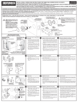
Install Strike Plate with Strike Subplate
a. Place the Strike Subplate in the prepared area in the
door jamb with the words " DOOR STOP SIDE---->"
visible and pointing towards the door jamb. Make sure
that the Subplate is positioned to receive the bolt from
the Deadbolt Latch when extended.
b. Insert two (S3) Strike Plate Screws through the holes
in the Subplate and tighten firmly.
c. Place the Strike Plate over the Subplate and insert two
(S3) Strike Plate Screws through the holes in the Strike
Plate. Tighten firmly.
HANDLESET DEADBOLT
INSTALLATION INSTRUCTIONS
READ THIS FIRST! Before installing your new Brinks handleset, please refer to the separate Door Preparation Instructions. Proceed with the instructions below only after you have confirmed that
your door has been properly prepared.
Carcasa del cilindro exterior
(El estilo varía con el número de serie)
Llaves (2)
Cerrojo de
pasador
deslizante
Escudo antipalanca
Tornillos (2) para metal (S5)
Placa frontal con esquinas cuadradas
Subplaca hembra del pasador de cerrojo
Tornillos (S3) de la Placa
hembra del cerrojo (4))
Tornillos (S1) del cerrojo (2)
Conjunto de la mariposa de cierre
Placa hembra del pasador del cerrojo (o cerrojo dormido)
Cola del cerrojo
Placa frontal del cerrojo
60 mm - o - 70 mm
Escudo antipalanca
Carcasa de cilindro exterior
Manivela en forma de cruz
Hoja de torsión
Hoja de torsión
Hoja de torsión
Conjunto de la mariposa de cierre
Mariposa de cierre
Seleccione la Placa frontal correcta
a. Seleccione la placa frontal correcta (esquinas cuadradas o redondeadas) para igualar el
recorte en la puerta.
b. En caso de no tener la placa frontal correcta ya instalada en el cerrojo, quite la placa
frontal instalada mediante la separación de la placa frontal del cerrojo y empuje en la
placa frontal correcta.
Instale el Cerrojo
a. Instale el cerrojo en el agujero en el canto de la puerta en la posición HACIA ARRIBA
("UP") tal como está marcado en el cerrojo con la manivela en forma de “cruz” en la parte
inferior.
b. Inserte dos Tornillos (S1) de cerrojo en los agujeros de la placa frontal y apriételos
firmemente.
Instale el Cilindro exterior – cilindro sencillo
a. Coloque el Escudo antipalanca en el agujero de 54 mm (2-1/8”) orientado de manera tal
que se deslice sobre el Cerrojo de pasador deslizante. El diámetro pequeño del
Escudo antipalanca se encaja en una ranura de la Carcasa de cilindro exterior.
b. Oriente la Hoja de torsión del cilindro en posición horizontal. Asegúrese que el Cerrojo
de pasador deslizante está retraído.
c.
NOTA: Si se instala en un agujero ya existente que tiene un diámetro inferior a 54 mm
(2-1/8”), usted puede decidir realizar la instalación sin el Escudo antipalanca en vez de
volver a perforar la puerta. El hecho de no instalar el Escudo antipalanca no afecta de
manera alguna el funcionamiento del pasador deslizante de cerrojo.
Inserte la Hoja de torsión a través de la manivela en forma de “cruz” del Cerrojo de
pasador deslizante y empuje la Carcasa de cilindro exterior hasta que quede al ras de la
puerta, con lo que se asegura que el Escudo antipalanca queda asentado en su ranura.
Instale el Conjunto de mariposa de cierre
a. Oriente la Mariposa de cierre a la posición vertical y deslice el Conjunto de la mariposa
de cierre por sobre la Hoja de torsión del cilindro exterior y empuje hasta que quede al
ras del interior de la puerta.
b. En puertas más delgadas, podrá ser necesario cortar la longitud de la Hoja de torsión.
Para cortar la hoja, rompa la Hoja de torsión en un sitio previamente muescado en la hoja.
c. Inserte los dos Tornillos (S5) para metal a través de los agujeros en el Conjunto de
mariposa de cierre hasta entrar en los agujeros en el Cilindro exterior, y apriételos
firmemente.
Para instalar la Placa hembra del cerrojo con la Subplaca
hembra del cerrojo
a. Coloque la Subplaca hembra del cerrojo en el área preparada en el marco o jamba de
la puerta con las palabras “DOOR STOP SIDE---->" visibles y apuntando hacia el marco
o jamba de la puerta. Asegúrese que la Subplaca esta colocada para recibir el pasador
del Cerrojo de pasador deslizante al extenderse dicho pasador.
b. Inserte dos Tornillos (S3) de la placa hembra del cerrojo a través de los agujeros en la
Subplaca y apriételos firmemente.
c. Coloque la Placa hembra del cerrojo sobre la Subplaca e inserte dos Tornillos (S3) de la
Placa hembra del cerrojo a través de los agujeros en la Placa hembra del cerrojo.
Apriételos firmemente.
INSTRUCCIONES PARA LA INSTALACIÓN DE PASADOR DE
CERROJO DE CONJUNTOS DE MANIJA DE CERRADURA
¡LEA ESTO PRIMERO! Antes de instalar su nuevo conjunto de manija de cerradura de Brinks, consulte las instrucciones de Preparación de la puerta provistas por separado. Proceda con las
instrucciones dadas a continuación después de que haya confirmado que su puerta ha sido preparada de manera correctamente.
Cómo seleccionar la distancia o “entrada” correcta
La distancia del canto o borde de la puerta hasta el centro del agujero en la cara de la puerta
se le conoce algunas veces como “entrada”. (Ver dibujo.) El cerrojo se puede ajustar para
una ‘entrada” de 2-3/8" (60 mm) o de 2-3/4" (70 mm). En la fábrica se ajusta el cerrojo para
una “entrada” de 2-3/8" (60 mm).
Cómo ajustar la entrada de 60 mm (2-3/8") a 70 mm (2-3/4"):
a. Retraiga el pasador del cerrojo.
b. Sujete la Placa frontal del cerrojo con la mano izquierda y la Cola del cerrojo con la mano
derecha.
c. Gire la Placa frontal del cerrojo en sentido de las manecillas del reloj (hacia usted)
aproximadamente 1/8 de vuelta.
d. Jale la Placa frontal del cerrojo hacia fuera en dirección izquierda hasta que se detenga.
e. Gire en el sentido opuesto a las manecillas del reloj hasta quede en posición de manera
tal que la muesca de enclavamiento se engrane en el orificio marcado 70 mm (2-3/4").
Cómo ajustar la distancia o “entrada” de 70 mm (2-3/4") a 60 mm (2-3/8"):
a. Retraiga el pasador del cerrojo.
b. Sujete la Placa frontal del cerrojo con la mano izquierda y la Cola del cerrojo con
la mano derecha.
c. Gire la Placa frontal del cerrojo en sentido de las manecillas del reloj (hacia usted)
aproximadamente 1/8 de vuelta.
d. Mientras que empuja en el extremo del pasador, empuje la Placa frontal del
cerrojo hacia adentro en dirección derecha hasta que se detenga.
e. Gire en el sentido opuesto a las manecillas del reloj hasta quede en posición de manera
tal que la muesca de enclavamiento se engrane en el orificio marcado 60 mm (2-3/8").


 1
1
 2
2


 Brinks Home Security 2057-120-1 Installation guide
 Brinks Home Security 2057-120-1 User guide
 Brinks Home Security 2057-105-1 User guide
 Brinks Home Security 2703-130 Installation guide
 Brinks Home Security 2057-120-1 Operating instructions
 Brinks Home Security 23042-119 Installation guide
 Brinks Home Security 23022-150 Installation guide
 Brinks Home Security 23042-119 Installation guide
 Brinks Home Security 23092-150 Installation guide


Grandeur 807484 Installation guide
Fusion H-AR-T2-0-ORB-L Operating instructions
Copper Creek FZ2610xRL-TB Installation guide
Schlage FA360, FA362, FA393 Installation guide
 Grip Tight Tools HDGR3ED03-4 Installation guide
Design House 783829 User manual
Veise KS02D User manual
 Grip Tight Tools GR3DB04C Installation guide

