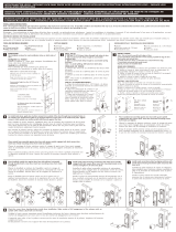
Veise KS02D User manual

Type
User manual
KS02D
Installation Manual
Before Installing the Lock, Please Check
Door Jamb and Door Preparation.
Door thickness:
1-3/8" to 2"
(35mm or 50mm)
2-1/8" (54mm)
2-1/8" (54mm)
3/8" (10mm)
8-7/16" (214mm)
Backset:
2-3/8" or 2-3/4"
(60 or 70mm)
1" (25mm)
1" (25mm)
5" (127mm)
TOOL REQUIRED: Do not use an electric
screwdriver during
installation.
IMPORTANT:
Do not load batteries until lock is
completely installed.
Installation Instructions of
Keypad Digital Deadbolt
Thank you for purchasing our products. Please review this manual thoroughly before
operating your device. All pictures in this manual are for illustration purpose only.
Actual product may vary due to product upgrade.
Latch x1
Drive-In Collar (Optional)
Strike x1
Exterior Assembly x1
Mounting Plate x1 Interior Assembly x1 Battery Cover x1 Strike Screws x2
Mounting plate Screws x2 Interior Assembly
Screws x3
Latch Screws x2
A B C
E F G
L
H
I
J K
D
Reset Tool x1 M
Parts List
Backup Key x2
Reinforcement
Plate x1
(optional)
Strike Screws
(H)
Interior Assembly
Screws (K)
Strike (D)
Backup key (A)
Mounting
plate Screws (J)
Battery
Cover (G)
Mounting
plate (E)
Interior
Assembly (F)
Exterior Assembly
(B)
Latch (C)
Latch Screws
(I)
Reinforcement
plate (D-1)
Measure to confirm
that the hole in the
door edge is 1"
(25mm).
Measure to confirm
that the backset is
either 2-3/8" or
2-3/4" (60 or 70mm)
Make sure the hole in
door frame is drilled a
minimum of 1"
(25mm) deep.
Measure to confirm
that the door is 1-3/8"
to 2" (35 mm or
50mm) thick.
A
Measure to
confirm that the
hole in the door is
2-1/8" (54mm).
B
CD
Prepare the door and check dimensions
1
STEP
2-3/8" or 2-3/4"
(60 or 70mm)
1"
25mm
1-3/8" to 2"
(35mm or 50mm)
chiseled
not chiseled
Drive-In Collar
(B)
Install the latch and strike
2
STEP
Hold the latch in front of the door hole,
with the latch face flush against the
door edge. Is the slotted hole centered
in the door hole?
No adjustment is required.
Proceed to next step.
Slotted hole is
NOT centered.
A
B
YES
NO
Rotate and pull the
latch as shown to
extend latch.
2-3/4"
(70mm)
2-3/8"
(60mm)
pull
Determine backset
and adjust the latch
Install the latch
Latch Screws ()
up
CUse a screwdriver to test if
deadbolt works smoothly.
DInstall strike on the door frame. Make sure the hole in door frame is
drilled a minimum of 1" (25mm)
deep.
IMPORTANT:
(Optional)
Install exterior assembly
3
STEP
Unlocked
Before installation, make sure the latch is
fully retracted (in the unlocked position)
IMPORTANT:
Locked
AB
Mounting plate Screws(J)
Keep parallel to
door edge.
With the latch fully retracted (in the unlocked
position), route the cable below the latch, and
insert the torque blade through the slot in the
latch.
Torque
blade
Secure the mounting plate with the
supplied screws. Do not overtighten
screws.
This step is required and crucial for the lock
to operate properly.
IMPORTANT:
Detect left/right hand door installation
5
STEP
Reset the lock to teach the lock the orientation of the door.
Install interior assembly
4
STEP
While the door is OPEN and
UNLOCKED, load 3 AA batteries
into the battery compartment.
Note:
For long last, please use all new,
non-rechargeable Alkaline
batteries only.
Press and hold the Reset button on
the interior assembly by using the
reset tool.
A B Load the 4th battery and keep holding
the reset button for 3 seconds, until
you hear the sound of "beep". The
latch bolt will extend to learn the
orientation of the door automatically.
C
Reset button
Unlocked
C
Unlocked
Keep the thumb turn in vertical position and install
the interior assembly.
Do not load batteries until lock is
completely installed.
IMPORTANT:
Push the battery cover out in
the direction as illustrated.
Insert the cable
connector to the
socket. Push the
connector in firmly
until it is completely
attached.
Attach Interior
Assembly to
Mounting Plate and
tighten 3 Screws.
A B
D
Horizontal
Interior Assembly
Screws (K)
Installation Instructions
of Handleset
TOOL REQUIRED: Do not use an electric
screwdriver during installation.
Thank you for purchasing our products. Please review this manual thoroughly before
operating your device. All pictures in this manual are for illustration purpose only.
Actual product may vary due to product upgrade.
1. Prepare the door
and check dimensions
If your door already has the holes shown in the picture
below, proceed to the next step, if your door does not
have holes, use the mounting template to drill a new hole.
2-1/8"
(54mm) 1"
(25mm)
2-3/8" or 2-3/4"
(60 or 70mm)
5"
(127mm)
Door thickness:
1-3/8" to 2"
(35mm or 50mm)
1"
25mm
G
A
B
H
C
D
E
F
F
Latch x1
Strike x1
B
Dust Cover x1 (optional)
C
Handle Lever x1
D
AHandleset x1
E
Handle Lever
& Handleset screws x3
F
Latch&Strike screws x4
G
Spacer x1
H
3. Install latch and strike
The latch should be aligned with the
chiseled properly.
IMPORTANT:
Make sure the hole in door frame is drilled a minimum of
1" (25mm) deep.
IMPORTANT:
2. Latch backset adjustment
Backset is the distance from the door edge to the center of the hole in the door.
The latch is provided with adjustable design which can fit either 2-3/8’’(60mm) or 2-3/4’’(70mm)
backset.
2-3/8"
(60mm)
2-3/4"
(70mm)
A. If the backset of your
door is 2-3/8"(60mm), no
need to adjust the latch.
B. If the backset of your door is 2-3/4"(70mm), please adjust the latch.
4. Install Handleset
The base of spindle must be
rotated aligning to the hole.
5. Install Handle Lever
Test the Handleset after installation.
Keep the door open, retract the latch by pressing knob from
outside and pushing the lever from inside of the door to test if
the Handleset works smoothly.
  • Page 1 1
  • Page 2 2
  • Page 3 3
  • Page 4 4
  • Page 5 5
  • Page 6 6
  • Page 7 7
  • Page 8 8
  • Page 9 9
  • Page 10 10

Veise KS02D User manual

Type
User manual

Ask a question and I''ll find the answer in the document

Finding information in a document is now easier with AI