GA-8I945GMMFY-RH Motherboard - 12 -
English
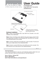
Figure 1.
Turn the screw to the unlocked position ( ).
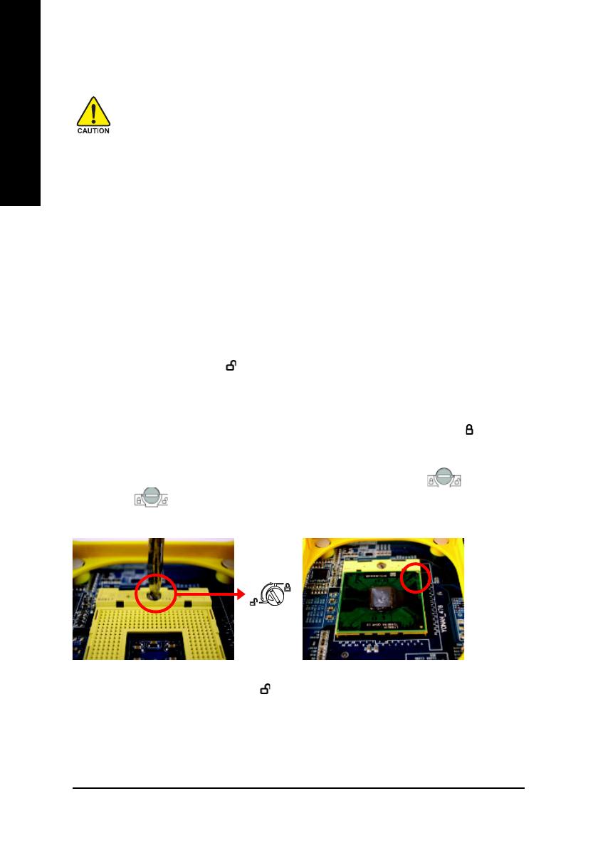
Figure 2
Align the CPU pin one marking (the gold triangle
marking) with pin one on the CPU socket. Care-
fully and gently insert the CPU into the socket.
1-3-1 Installation of the CPU
Before installing the CPU, please comply with the following directions:
1. Ensure that the motherboard supports the CPU.
2. When inserting the CPU, carefully align the CPU pin one marking with pin one (the
indented corner) on the CPU socket. The CPU will not fit if inserted incorrectly.
3. Please add an even thin layer of heat paste between the CPU and CPU cooler.
4. Ensure that the CPU cooler is installed on the CPU prior to system use, otherwise
overheating and permanent damage of the CPU may occur.
5. Set the CPU host frequency in accordance with the CPU specifications. It is not
recommended that the system bus frequency be set beyond hardware specifica-
tions since it does not meet the required standards for the peripherals. If you wish to set
the frequency beyond the proper specifications, please do so according to your hard
ware specifications including the CPU, graphics card, memory, hard drive, etc.
1-3 Installation of the CPU and CPU Cooler
Check the CPU pins to see that none are bent. Use a flathead screwdriver to turn the screw on the CPU
socket to the unlocked position ( ) (Figure 1). Align the CPU pin one marking (the gold triangle
marking) with the pin one (the indented corner) on the CPU socket. Gently insert the CPU into the socket
and ensure that all pins are properly inserted (Figure 2). Note: If you install the CPU in the wrong
direction, the CPU will not insert properly. If this occurs, rather than applying force, change the insert
direction of the CPU. Finally, make sure to turn the socket screw to the locked position ( ) to secure
the CPU (Figure 3).
The instructions on installing the CPU below are for reference only. CPU socket design may slightly
differ depending on CPU socket supplier. For example, on some CPU sockets, is to release
the CPU and is to lock the CPU in place. Installation of the CPU is dependent on the design of
the CPU socket on your motherboard.