Page is loading ...

®
CUV4X-DLS
JumperFree™ PC133/VC133
133MHz FSB AGP Pro/4X
Dual Socket 370 Motherboard
USER’S MANUAL

ASUS CUV4X-DLS User’s Manual
2
USER'S NOTICE
Product Name: ASUS CUV4X-DLS
Manual Revision: 1.03 E652
Release Date: January 2001
No part of this manual, including the products and software described in it, may be reproduced,
transmitted, transcribed, stored in a retrieval system, or translated into any language in any form or
by any means, except documentation kept by the purchaser for backup purposes, without the express
written permission of ASUSTeK COMPUTER INC. (“ASUS”).
ASUS PROVIDES THIS MANUAL “AS IS” WITHOUT WARRANTY OF ANY KIND, EITHER
EXPRESS OR IMPLIED, INCLUDING BUT NOT LIMITED TO THE IMPLIED WARRANTIES
OR CONDITIONS OF MERCHANTABILITY OR FITNESS FOR A PARTICULAR PURPOSE. IN
NO EVENT SHALL ASUS, ITS DIRECTORS, OFFICERS, EMPLOYEES OR AGENTS BE LIABLE
FOR ANY INDIRECT, SPECIAL, INCIDENTAL, OR CONSEQUENTIAL DAMAGES
(INCLUDING DAMAGES FOR LOSS OF PROFITS, LOSS OF BUSINESS, LOSS OF USE OR
DATA, INTERRUPTION OF BUSINESS AND THE LIKE), EVEN IF ASUS HAS BEEN ADVISED
OF THE POSSIBILITY OF SUCH DAMAGES ARISING FROM ANY DEFECT OR ERROR IN
THIS MANUAL OR PRODUCT.
Product warranty or service will not be extended if: (1) the product is repaired, modified or altered,
unless such repair, modification of alteration is authorized in writing by ASUS; or (2) the serial
number of the product is defaced or missing.
Products and corporate names appearing in this manual may or may not be registered trademarks or
copyrights of their respective companies, and are used only for identification or explanation and to
the owners’ benefit, without intent to infringe.
• VIA is a registered trademark of VIA Technologies, Inc.
• Intel, LANDesk and Pentium are registered trademarks of Intel Corporation.
• Windows and MS-DOS are registered trademarks of Microsoft Corporation.
• Adobe and Acrobat are registered trademarks of Adobe Systems Incorporated.
• Trend and ChipAwayVirus are trademarks of Trend Micro, Inc.
• Symbios is a registered trademark of Symbios Logic Corporation.
The product name and revision number are both printed on the product itself. Manual revisions are
released for each product design represented by the digit before and after the period of the manual
revision number. Manual updates are represented by the third digit in the manual revision number.
For previous or updated manuals, BIOS, drivers, or product release information, contact ASUS at
http://www.asus.com.tw or through any of the means indicated on the following page.
SPECIFICATIONS AND INFORMATION CONTAINED IN THIS MANUAL ARE FURNISHED
FOR INFORMATIONAL USE ONLY, AND ARE SUBJECT TO CHANGE AT ANY TIME
WITHOUT NOTICE, AND SHOULD NOT BE CONSTRUED AS A COMMITMENT BY ASUS.
ASUS ASSUMES NO RESPONSIBILITY OR LIABILITY FOR ANY ERRORS OR
INACCURACIES THAT MAY APPEAR IN THIS MANUAL, INCLUDING THE PRODUCTS AND
SOFTWARE DESCRIBED IN IT.
Copyright © 2001 ASUSTeK COMPUTER INC. All Rights Reserved.

ASUS CUV4X-DLS User’s Manual 3
ASUS CONTACT INFORMATION
ASUSTeK COMPUTER INC. (Asia-Pacific)
Marketing
Address: 150 Li-Te Road, Peitou, Taipei, Taiwan 112
Telephone: +886-2-2894-3447
Fax: +886-2-2894-3449
Email: [email protected]
Technical Support
MB/Others (Tel): +886-2-2890-7121 (English)
Notebook (Tel): +886-2-2890-7122 (English)
Desktop/Server (Tel):+886-2-2890-7123 (English)
Fax: +886-2-2893-7775
Email: [email protected]
WWW: www.asus.com.tw
FTP: ftp.asus.com.tw/pub/ASUS
ASUS COMPUTER INTERNATIONAL (America)
Marketing
Address: 6737 Mowry Avenue, Mowry Business Center, Building 2
Newark, CA 94560, USA
Fax: +1-510-608-4555
Email: [email protected]
Technical Support
Fax: +1-510-608-4555
Email: [email protected]
WWW: www.asus.com
FTP: ftp.asus.com/Pub/ASUS
ASUS COMPUTER GmbH (Europe)
Marketing
Address: Harkortstr. 25, 40880 Ratingen, BRD, Germany
Fax: +49-2102-442066
Email: [email protected] (for marketing requests only)
Technical Support
Hotline: MB/Others: +49-2102-9599-0 Notebook: +49-2102-9599-10
Fax: +49-2102-9599-11
Support (Email): www.asuscom.de/de/support (for online support)
WWW: www.asuscom.de
FTP: ftp.asuscom.de/pub/ASUSCOM

ASUS CUV4X-DLS User’s Manual
4
CONTENTS
1. INTRODUCTION ............................................................................. 7
1.1 How This Manual Is Organized ................................................... 7
1.2 Item Checklist .............................................................................. 7
2. FEATURES ........................................................................................ 8
2.1 ASUS CUV4X-DLS Motherboard .............................................. 8
2.1.1 Specifications ..................................................................... 8
2.1.2 Performance...................................................................... 10
2.1.3 Intelligence ....................................................................... 11
2.2 Motherboard Components.......................................................... 12
2.2.1 Component Locations....................................................... 13
3. HARDWARE SETUP ...................................................................... 14
3.1 Motherboard Layout .................................................................. 14
3.2 Layout Contents ......................................................................... 15
3.3 Hardware Setup Procedure......................................................... 17
3.4 Motherboard Settings ................................................................. 17
3.5 System Memory ......................................................................... 23
3.5.1 General DIMM Notes....................................................... 23
3.5.2 Memory Installation ......................................................... 24
3.6 Central Processing Unit (CPU) .................................................. 25
3.6.1 CPU Installation ............................................................... 26
3.7 Expansion Cards ........................................................................ 27
3.7.1 Installing an Expansion Card ........................................... 27
3.7.2 Assigning IRQs for Expansion Cards .............................. 28
3.7.3 Accelerated Graphics Port (AGP) Pro Slot ...................... 29
3.8 Connectors ................................................................................ 31
3.8.1 External Connectors ......................................................... 31
3.8.2 Internal Connectors .......................................................... 34
3.9 Starting Up the First Time.......................................................... 44
4. BIOS SETUP..................................................................................... 45
4.1 Managing and Updating Your BIOS .......................................... 45
4.1.1 Upon First Use of the Computer System.......................... 45
4.1.2 Updating BIOS Procedures .............................................. 47
4.2 BIOS Setup Program.................................................................. 49
4.2.1 BIOS Menu Bar................................................................ 50
4.2.2 Legend Bar ....................................................................... 50

ASUS CUV4X-DLS User’s Manual 5
CONTENTS
4.3 Main Menu................................................................................. 52
4.3.1 Primary & Secondary Master/Slave ................................. 53
4.3.2 Keyboard Features............................................................ 56
4.4 Advanced Menu ......................................................................... 58
4.4.1 Chip Configuration........................................................... 62
4.4.2 I/O Device Configuration ................................................. 65
4.4.3 PCI Configuration ............................................................ 67
4.4.4 Shadow Configuration ...................................................... 71
4.5 Power Menu ............................................................................... 72
4.5.1 Power Up Control............................................................. 74
4.5.2 Hardware Monitor ............................................................ 75
4.6 Boot Menu ................................................................................. 76
4.7 Exit Menu................................................................................... 78
5. SOFTWARE SETUP....................................................................... 81
5.1 Operating Systems ..................................................................... 81
5.1.1 Windows 98 First Time Installation ................................. 81
5.2 CUV4X-DLS Motherboard Support CD ................................... 81
5.2.1 Installation Menu.............................................................. 81
6. SOFTWARE REFERENCE ........................................................... 83
6.1 ASUS PC Probe ......................................................................... 83
7. APPENDIX........................................................................................ 89
7.1 PCI-L101 Fast Ethernet Card..................................................... 89
7.1.1 Features ............................................................................ 90
7.1.2 Software Driver Support .................................................. 90
7.1.3 Question and Answer........................................................ 90
7.2 Modem Riser.............................................................................. 91
7.2.1 56K Software Modem ...................................................... 91
7.2.2 Primary/Seconday MR ..................................................... 91
7.2.3 Hardware Installation Procedure ...................................... 91
7.2.4 Software Setup in Windows 98 ........................................ 92
7.3 Glossary ..................................................................................... 93
INDEX ................................................................................................... 97

ASUS CUV4X-DLS User’s Manual
6
FCC & DOC COMPLIANCE
Federal Communications Commission Statement
This device complies with FCC Rules Part 15. Operation is subject to the following
two conditions:
• This device may not cause harmful interference, and
• This device must accept any interference received, including interference that
may cause undesired operation.
This equipment has been tested and found to comply with the limits for a Class B
digital device, pursuant to Part 15 of the FCC Rules. These limits are designed to
provide reasonable protection against harmful interference in a residential
installation. This equipment generates, uses and can radiate radio frequency energy
and, if not installed and used in accordance with manufacturer's instructions, may
cause harmful interference to radio communications. However, there is no guarantee
that interference will not occur in a particular installation. If this equipment does
cause harmful interference to radio or television reception, which can be determined
by turning the equipment off and on, the user is encouraged to try to correct the
interference by one or more of the following measures:
• Re-orient or relocate the receiving antenna.
• Increase the separation between the equipment and receiver.
• Connect the equipment to an outlet on a circuit different from that to which
the receiver is connected.
• Consult the dealer or an experienced radio/TV technician for help.
WARNING! Any changes or modifications to this product not expressly approved
by the manufacturer could void any assurances of safety or performance and
could result in violation of Part 15 of the FCC Rules.
Reprinted from the Code of Federal Regulations #47, part 15.193, 1993. Washington DC: Office of the
Federal Register, National Archives and Records Administration, U.S. Government Printing Office.
Canadian Department of Communications Statement
This digital apparatus does not exceed the Class B limits for radio noise emissions
from digital apparatus set out in the Radio Interference Regulations of the Canadian
Department of Communications.
This Class B digital apparatus complies with Canadian ICES-003.
Cet appareil numérique de la classe B est conforme à la norme NMB-003 du Canada.

ASUS CUV4X-DLS User’s Manual 7
1.1 How This Manual Is Organized
This manual is divided into the following sections:
1. INTRODUCTION Manual information and checklist
2. FEATURES Production information and specifications
3. HARDWARE SETUP Instructions on setting up the motherboard.
4. BIOS SETUP Instructions on setting up the BIOS
5. SOFTWARE SETUP Instructions on setting up the included software
6. SOFTWARE REFERENCE Reference material for the included software
7. APPENDIX Optional items and general reference
1.2 Item Checklist
Check that your package is complete. If you discover damaged or missing items,
contact your retailer.
1. INTRODUCTION
1. INTRODUCTION
Manual / Checklist
Package Contents
(1) ASUS Motherboard
(1) 40-pin 80-conductor ribbon
cable for internal UltraDMA/66
or UltraDMA/33 IDE drives
(2) 68-pin LVD SCSI ribbon cable
for Ultra160/Ultra3 devices
(1) Ribbon cable for two 3.5”
floppy disk drives
(1) CPU terminator
(1) ASUS Support CD with drivers
and utilities
(1) Bag of spare jumper caps
(1) ASUS 2-port USB Connector
Set
(1) IDE cable
(1) User’s Manual
Optional Items
ASUS Modem MR
ASUS IrDA-compliant infrared
module
ASUS PCI-L101 Wake-On-LAN
10/100 Ethernet Card

8
ASUS CUV4X-DLS User’s Manual
2.1 ASUS CUV4X-DLS Motherboard
The ASUS CUV4X-DLS motherboard is targeted diversely for home PCs and entry-
level workstations and servers. Powered by dual Intel
®
Pentium
®
III processors and
bundled with advanced features to provide superlative performance, the CUV4X-DLS
efficiently complies with today’s demand for a flexible high-integration system.
2.1.1 Specifications
• Latest Processor Support
Intel Pentium
®
III 133MHz FSB Coppermine core FC-PGA
Intel Pentium
®
III 100MHz FSB Coppermine core FC-PGA
• North Bridge System Chipset: Features the VIA VT82C694XDP system
controller PCI-to-ISA bridge with support for AGP Pro/4X/2X mode;
133/100MHz Front Side Bus (FSB); and 133MHz memory bus.
• South Bridge System Chipset: VIA VT82C686B PCIset with PCI Super I/O
integrated peripheral controller supports UltraDMA/100/66 for burst mode data
transfer rates of up to 100MB/sec, and USB controller with root hub for four
USB ports.
• PC133 SDRAM / VC133 VCM / HSDRAM Support: Equipped with four
Dual Inline Memory Module (DIMM) sockets to support up to 4GB of memory
using Intel PC133/100-compliant or NEC’s VC133-compliant Virtual Channel
(VC) SDRAMs, and Enhanced Memory System’s High-speed DRAMs
(HSDRAMs). VC SDRAM and HSDRAM are new DRAM core architectures
that dramatically improves the memory system’s ability to service high
multimedia requirements.
• JumperFree™ Mode: Allows processor settings and easy overclocking of
frequency and Vcore voltage through BIOS setup when the JumperFree™ mode
is enabled. Easy-to-use DIP switches come with the motherboard board to allow
manual adjustment of the processor external/internal frequency.
• Ultra SCSI Support: Equipped with the LSI 53C1010-33 Ultra160/Ultra3 32-bit
33MHz dual-channel SCSI controller that supports up to 30 SCSI devices. BIOS
configurable onboard SCSI settings.
• UltraDMA/100 Support: Comes with an onboard PCI Bus Master IDE controller
with two connectors that support four IDE devices on two channels. Supports
UltraDMA/100, UltraDMA/66, UltraDMA/33, PIO Modes 3 & 4, Bus Master
IDE DMA Mode 2, and Enhanced IDE devices, such as DVD-ROM, CD-ROM,
CD-R/RW, LS-120, and Tape Backup drives.
• AGP Pro Slot: Comes with an Accelerated Graphics Port (AGP) Pro slot that
supports high performance AGP cards targeted at 3D graphical applications
supporting 133MHz 4X mode. The slot is backward compatible with AGP 4X/
2X cards.
2. FEATURES
Specifications
2. FEATURES

ASUS CUV4X-DLS User’s Manual 9
2. FEATURES
2. FEATURES
Specifications
• LAN Support: Features the Intel 82559 Fast-Ethernet LAN controller that fully
supports 10BASE-T/100BASE-TX.
• Wake-On-LAN: Supports Wake-On-LAN activity through a WOL connector
or an optional ASUS PCI-L101 10/100 Fast Ethernet PCI card.
• Wake-On-Ring: Supports Wake-On-Ring activity through a PCI modem card
that supports a WOR connector.
• PC Health Monitoring: Provides an easy way to test and manage system status
information, such as CPU and system voltages, temperatures, and fan status
through the onboard hardware ASUS ASIC and the bundled ASUS PC Probe.
• SMBus: Features the System Management Bus interface used to physically
transport commands and information between SMBus devices.
• PCI Expansion Slots: Provides five 32-bit PCI (Rev. 2.2) expansion slots that
support Bus Master PCI cards, such as SCSI or LAN cards, with 133MB/s
maximum throughput.
• Super Multi-I/O: Provides two high-speed UART compatible serial ports and
one parallel port with EPP and ECP capabilities. UART2 can also be directed
from COM2 to the Infrared Module for wireless connections.
• Smart BIOS: 2MB firmware provides Vcore and CPU/SDRAM frequency
adjustments, boot block write protection, and HD/SCSI/MO/ZIP/CD/Floppy boot
selection.
• Enhanced ACPI and Anti-Boot Virus Protection: Programmable BIOS (Flash
EEPROM) that offers enhanced ACPI for Windows 98 compatibility, built-in
firmware-based virus protection, and autodetection of most devices for a virtual
automatic setup.
• IrDA: Supports an optional infrared port module for wireless interface.
• Concurrent PCI: Concurrent PCI allows multiple PCI transfers from PCI master
busses to the memory and processor.
• Desktop Management Interface (DMI): Supports DMI through BIOS that
allows hardware to communicate within a standard protocol and create a higher
level of compatibility. (Requires DMI-enabled components.)
• Onboard LED: Comes with a power LED that lights up if there is any standby
power on the motherboard. This LED acts as a reminder to turn off the system
power before plugging or unplugging devices to prevent damage to the
motherboard, peripherals, and other system components.
• Onboard Audio: Audio models come with the AC ‘97-compliant AD1881A
audio controller with 3D sound circuitry and full duplex sampling rate conversion
from 7kHz to 48kHz.
• Easy Connectivity and System Information Access: Supports an optional
ASUS iPanel, an easy-to-access box with system diagnostic display area, system
status LEDs, USB ports, and hot keys. The AFPANEL connector on the
motherboard accommodates the ASUS iPanel .

10
ASUS CUV4X-DLS User’s Manual
2. FEATURES
Performance
2. FEATURES
2.1.2 Performance
• ACPI Ready: Advanced Configuration Power Interface (ACPI) provides more
Energy Saving Features for operating systems that support OS Direct Power
Management (OSPM) functionality. With these features employed in the OS,
PCs can be ready around the clock but comply with energy saving standards. To
fully utilize the ACPI benefits, use an ACPI-supported OS such as Windows 98.
• PC’99 Compliant: Both the BIOS and hardware levels of ASUS smart series
motherboards are PC’99 compliant. The new PC’99 requirements for systems
and components are based on the following high-level goals: Support for Plug-
n-Play compatibility and power management for configuring and managing all
system components, and 32-bit device drivers and installation procedures for
Windows 95/98/NT. Color-coded connectors and descriptive icons make
identification easy as required by PC’99.
• High-Speed Data Transfer Interface: Support for UltraDMA/100 through the
onboard IDE bus master controller. doubles the UltraDMA/33 burst transfer
rate to 66.6MB/s. UltraDMA/100 is backward compatible with DMA/66, DMA/
33, and other existing DMA devices to save the need to upgrade current EIDE/
IDE drives. (UltraDMA/66 requires a 40-pin 80-conductor cable).
• Concurrent PCI: Concurrent PCI allows multiple PCI transfers from PCI master
busses to the memory and processor.
• VCM/SDRAM Optimized Performance: This motherboard supports the new
generation memory, NEC 64Mb Virtual Channel Memory (VCM) Synchronous
Dynamic Random Access Memory (SDRAM), that is compatible to the industry
standard SDRAM. The VCM core design provides up to 50% higher SDRAM
speed at reduced power consumption of about 30%. This motherboard also
supports the standard SDRAM for a the data transfer rate of up to 1.064GB/s using
PC133-compliant SDRAMs and up to 800MB/s using PC100-compliant
SDRAMs.

ASUS CUV4X-DLS User’s Manual 11
2. FEATURES
2. FEATURES
Intelligence
2.1.3 Intelligence
• Auto Fan Off: The system fans powers off automatically even in sleep mode.
This function reduces both energy consumption and system noise, and is an
important feature in implementing silent PC systems.
• Dual Function Power Button: Pushing the power button for less than 4 seconds
when the system is in the working state places the system into one of two states:
sleep mode or soft-off mode, depending on the BIOS or OS setting (see PWR
Button < 4 Secs in 4.5 Power Menu). When the power button is pressed for
more than 4 seconds, the system enters the soft-off mode regardless of the BIOS
setting.
• Fan Status Monitoring and Alarm: To prevent system overheat and system
damage, the CPU and system fans can be monitored for RPM and failure. All
fans are set for its normal RPM range and alarm thresholds.
• Power LED (requires ACPI OS support): The power LED indicates the system
status.
• Remote Ring-On (requires modem): This allows a computer to be turned on
remotely through an internal or external modem. With this benefit on-hand, users
can access vital information from their computers anywhere.
• System Resources Alert: Today’s operating systems such as Windows 95/98/
NT and OS/2, require much more memory and hard drive space to present
enormous user interfaces and run large applications. The system resource monitor
warns the user before the system resources are used up to prevent possible
application crashes. Suggestions provide the user some information on managing
their limited resources more efficiently.
• Temperature Monitoring and Alert: CPU temperature is monitored by the
ASUS ASIC through the CPU’s internal thermal diode (on Pentium III and
Celeron) to prevent system overheat and system damage.
• Voltage Monitoring and Alert: System voltage levels are monitored to ensure
stable voltage to critical motherboard components. Voltage specifications are
more critical for future processors, so monitoring is necessary to ensure proper
system configuration and management.
• Chassis Intrusion Detection: Supports chassis-intrusion monitoring through
the ASUS ASIC. A chassis intrusion event is kept in memory on battery power
for more protection.

12
ASUS CUV4X-DLS User’s Manual
2. FEATURES
2. FEATURES
M/B Components
Location
Processor Support 2 Socket 370 for Pentium III Coppermine Processors ............. 1
Feature Setting DIP Switches ................................................. 11
Chipsets VIA VT82C694XDP System Controller ................................. 22
VIA VT82C686B PCIset......................................................... 13
2Mbit Programmable Flash EEPROM ................................... 16
Main Memory Maximum 4GB support
4 DIMM Sockets ...................................................................... 4
PC133 SDRAM support
Expansion Slots 5 PCI Slots .............................................................................. 20
1 Accelerated Graphics Port (AGP) Pro/4X Slot ................... 21
System I/O 1 Floppy Disk Drive Connector ............................................... 7
2 IDE Connectors (UltraDMA/100 Support) ......................... 10
1 ASUS iPanel Connector ........................................................ 6
1 Parallel Port ............................................................... (Top) 24
2 Serial Ports (COM1/COM2) ............................... (Bottom) 24
LAN Connector (RJ-45) ............................................... (Top) 25
USB Connectors (Port 0 & Port 1) ........................ (Bottom) 25
USB Connectors (Port 2 & Port 3) .......................................... 9
1 PS/2 Mouse Connector .............................................. (Top) 26
1 PS/2 Keyboard Connector ................................... (Bottom) 26
Network Features Intel 82559 Fast Ethernet Controller ...................................... 18
Wake-On-LAN Connector...................................................... 17
Wake-On-Ring Connector ...................................................... 15
Hardware Monitoring System Voltage Monitoring (integrated in ASUS ASIC) ....... 12
4 Fan Power and Speed Monitoring Connectors
Special Features LSI 32-bit (33MHz) Ultra160 SCSI Controller ........................ 8
Onboard SCSI Connectors ....................................................... 5
Onboard LED ......................................................................... 14
Audio Features (on audio models only)
AC ’97 v2.1 Audio Codec ...................................................... 19
1 Game/MIDI Port.................................................................. 23
1 Line Out Connector ............................................................. 23
1 Line In Connector................................................................ 23
1 Microphone Connector ........................................................ 23
Power Auxiliary Power Connector ...................................................... 2
ATX Power Supply Connector ................................................. 3
Form Factor AT X
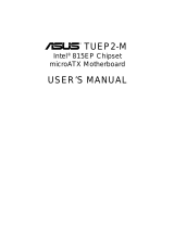
2.2 Motherboard Components
See opposite page for locations.

ASUS CUV4X-DLS User’s Manual 13
2. FEATURES
2. FEATURES
Motherboard Parts
2.2.1 Component Locations
20
26
24
23
25
3
21
4
71012 616
17
18
1315 9
1
2
58
22
14 11
19

14
ASUS CUV4X-DLS User’s Manual
3. HARDWARE SETUP
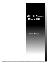
3.1 Motherboard Layout
Motherboard Layout
3. H/W SETUP
25.4cm (10.0in)
30.5cm (12.0in)
AUX Power
Connector
SMB
CLRTC
®
Primary IDE
SecondaryIDE
ATX Power Connector
PANEL
PCI 2
WOL_CON
FLOPPY
CUV4X-DLS
Audio
Codec
MICIN
Socket 370
USBPORT
CHASSIS
VIA
VT82C686B
Chipset
ASUS
ASIC
with Hardware
Monitor
PCI 1
DIMM Socket 1 (64/72-bit, 168-pin module)
0
1
DIMM Socket 2 (64/72-bit, 168-pin module)
2
3
DIMM Socket 3 (64/72-bit, 168-pin module)
4
5
IR
Accelerated Graphics Port (AGP PRO)
VIA
VT82C694XDP
Chipset
Flash EEPROM
(Programable BIOS)
CR2032 3V
Lithium Cell
CMOS Power
PCI 4
PCI 3
PCI 5
GAME_AUDIO
Mic
In
Line
Out
Line
In
WOR
AUX
MODEM
CD
LED
IDELED
JEN
PS/2
T: Mouse
B: Keyboard
USB1
USB2
SCSI_EN
COM1
PARALLEL PORT
COM2
Socket 370
LSI
SCSI
Controller
896/
1010-66
DIMM Socket 4 (64/72-bit, 168-pin module)
6
7
DIP Switches
DIP_SW
PWR_FAN
CPU_FAN
CHA_FAN
SCSI-A
SCSI-B
AFPANEL
USBPWR1
CPU_FAN2
LAN_EN
LAN
Controller
USBPWR2
AAPANEL
Bottom:
RJ-45
Top:

ASUS CUV4X-DLS User’s Manual 15
3. HARDWARE SETUP
3.2 Layout Contents
Motherboard Settings
1) JEN p. 18 JumperFree Mode Setting (Disable/Enable)
2) DIP_SW 5–8 p. 19 CPU External Frequency Selection
3) DIP_SW 1-4 p. 20 CPU Core:BUS Frequency Multiple Selection
4) R153 p. 21 Clear RTC RAM
5) LAN_EN p. 21 LAN Setting (Disable/Enable)
6) SCSI_EN p. 22 SCSI Setting (Dsiable/Enable)
7) USBPWR1/2 p. 22 USB Wake-up Jumpers
Expansion Slots/Sockets
1) DIMM 1/2/3/4 p. 23 System Memory Support
2) Socket 370 p. 25 CPU Support
3) PCI 1/2/3/4/5 p. 27 32-bit PCI Bus Expansion Slots
4) AGP Pro p. 29 Accelerated Graphics Port Slot
Connectors
1) PS2KBMS p. 31 PS/2 Mouse Port (6-pin female)
2) PS2KBMS p. 31 PS/2 Keyboard Port (6-pin female)
3) RJ-45 p. 32 Fast Ethernet LAN Port (RJ-45)
4) USB p. 32 Universal Serial Bus Ports 1 & 2 (two 4-pin female)
5) PRINTER p. 32 Parallel Port (25-pin female)
6) COM1/COM2 p. 33 Serial Ports (9-pin /10-1 pin male)
7) GAME_AUDIO p. 33 Game/MIDI Ports (15-pin female, 1/8” jacks)
8) IDELED p. 34 IDE Activity LED (2-pin)
9) FLOPPY p. 34 Floppy Disk Drive Connector (34-pin)
10) PRIMARY IDE p. 35 IDE Connectors (Two 40-1 pin)
SECONDARY IDE
11) SCSI-A/SCSI-B p. 36 Ultra160/Ultra3 SCSI Connectors (two 68-pin)
12) WOL_CON p. 37 Wake-On-LAN Connector (3-pin)
13) WOR p. 37 Wake-On-Ring Connector (2-pin)
14) CPU/PWR/CHA_FAN p. 38 CPU, Power, and Chassis Fan Connectors (four 3-pin)
15) USBPORT p. 38 USB Header (10-1 pin)
16) IR p. 39 Infrared Module Connector (5-pin)
17) CHASSIS p. 39 Chassis Intrusion Lead (4-1 pin)
18) ATXPWR/EAUXPWR p. 40 ATX/Auxiliary Power Supply Connectors (20-pin/6-pin)
19) SMB p. 40 SMBus Connector (5-1 pin)
20) AFPANEL p. 41 ASUS iPanel Connector (12-1 pin)
21) AUDIO_PANEL p. 41 Audio Panel Connector (12-1 pin)
Layout Contents
3. H/W SETUP

16
ASUS CUV4X-DLS User’s Manual
3. HARDWARE SETUP
Layout Contents
3. H/W SETUP
22) CD/AUX/MODEM p. 42 Internal Audio Connectors (4-1 pin)
23) MICIN p. 42 Internal Microphone Connector (3-pin)
24)
PWR.LED (
PANEL
)
p. 43 System Power LED Lead (3-pin)
25) SPEAKER (PANEL) p. 43 System Warning Speaker Lead (4-pin)
26) MSG.LED (PANEL) p. 43 System Message LED Lead (2-pin)
27) SMI (PANEL) p. 43 System Management Interrupt Lead (2-pin)
28) PWR.SW (PANEL) p. 43 ATX / Soft-Off Switch Lead (2-pin)
29) RESET (PANEL) p. 43 Reset Switch Lead (2-pin)

ASUS CUV4X-DLS User’s Manual 17
3. HARDWARE SETUP
3.3 Hardware Setup Procedure
Complete the following steps before using your computer:
1. Check motherboard settings
2. Install memory modules
3. Install the Central Processing Unit (CPU)
4. Install Expansion Cards
5. Connect ribbon cables, panel wires, and power supply cables
6. Configure the BIOS parameter settings
3.4 Motherboard Settings
This section tells you how to change motherboard function settings through the
switches and/or jumpers.
3. H/W SETUP
Motherboard Settings
CUV4X-DLS Onboard LED
ON
OFF
Standby
Power
Powered
Off
LED1
®
CUV4X-DLS
WARNING! Computer motherboards and expansion cards contain very delicate
Integrated Circuit (IC) chips. To avoid damaging them due to static electricity,
follow these precautions whenever you work on your computer.
1. Unplug the computer when working on the internal components.
2. Use a grounded wrist strap or touch a safely grounded object or to a metal
object, such as the power supply case, before handling computer components.
3. Hold components by the edges and try not to touch the IC chips on them.
4. Whenever you uninstall any component, place the components on a grounded
antistatic pad or in the bag that came with the components.
5. Before you install or remove any component, ensure that the ATX power
supply is switched off or the power cord is detached from the power
supply. Failure to do so may cause severe damage to the motherboard,
peripherals, and/or components.
(TIP: When lit, the onboard LED indicates that the system is in suspend or
soft-off mode, not powered OFF. See illustration below.)

18
ASUS CUV4X-DLS User’s Manual
3. HARDWARE SETUP
3. H/W SETUP
Motherboard Settings
Motherboard Frequency Settings (DIP Switches)
The motherboard frequency is adjusted through the DIP switches. The white block
represents the switch’s position. The illustration below shows all the switches in the
OFF position.
CUV4X-DLS DIP Switches
ON
12345678
OFF
ON
< Frequency Multiple
< Frequency Multiple
< Frequency Multiple
< Frequency Multiple
< Frequency Selection
< Frequency Selection
< Frequency Selection
< Frequency Selection
®
CUV4X-DLS
1) JumperFree™ Mode (JEN)
This jumper allows you to enable or disable the JumperFree™ mode. The
JumperFree™ mode allows processor settings to be made through the BIOS
setup (see 4.4 Advanced Menu).
Setting JEN
Enable (JumperFree) [2-3] (default)
Disable (Jumper) [1-2]
®
CUV4X-DLS
CUV4X-DLS JumperFree™ Mode Setting
Jumper Mode JumperFree Mode
(Default)
JEN
ON
12345678
OFF
DIP_SW
2
3
1
2
NOTE: In JumperFree™ mode, set all DIP switches (DIP_SW) to OFF.

ASUS CUV4X-DLS User’s Manual 19
3. HARDWARE SETUP
3. H/W SETUP
Motherboard Settings
2) CPU External Frequency Selection (DIP_SW Switches 5–8)
This option tells the clock generator what frequency to send to the CPU, DRAM,
and the PCI bus. This allows the selection of the CPU’s External frequency (or
BUS Clock). The BUS Clock multiplied by the Frequency Multiple equals the
CPU’s Internal frequency (the advertised CPU speed).
NOTE: Overclocking your processor is not recommended. It may result in a slower
speed.
WARNING! Frequencies other than the recommended CPU bus frequencies are
not guaranteed to be stable.
CUV4X-DLS CPU External
Frequency Selection
83MHz
42MHz
ON
12345678
66MHz
33MHz
ON
12345678
68MHz
34MHz
ON
12345678
75MHz
37MHz
ON
12345678
80MHz
40MHz
ON
12345678
CPU
PCI
CPU
PCI
100MHz
33MHz
ON
12345678
CPU
PCI
103MHz
34MHz
ON
12345678
105MHz
35MHz
ON
12345678
110MHz
36MHz
ON
12345678
124MHz
31MHz
ON
12345678
CPU
PCI
CPU
PCI
®
CUV4X-DLS
CPU
PCI
150MHz
37MHz
ON
12345678
133MHz
33MHz
ON
12345678
140MHz
35MHz
ON
12345678
120MHz
40MHz
ON
12345678
115MHz
38MHz
ON
12345678
112MHz
37MHz
ON
12345678

20
ASUS CUV4X-DLS User’s Manual
3. HARDWARE SETUP
3. H/W SETUP
Motherboard Settings
3) CPU Core:BUS Frequency Multiple (DIP_SW Switches 1–4)
This option sets the frequency multiple between the Internal frequency of the
CPU and the CPU’s External frequency. These must be set in conjunction with the
CPU Bus Frequency.
CUV4X-DLS CPU Core:Bus
Frequency Multiple
2.0x
ON
12345678
2.5x
ON
12345678
3.0x
ON
12345678
3.5x
ON
12345678
4.0x
ON
12345678
4.5x
ON
12345678
5.0x
ON
12345678
5.5x
ON
12345678
6.0x
ON
12345678
6.5x
ON
12345678
7.0x
ON
12345678
7.5x
ON
12345678
8.0x
ON
12345678
®
CUV4X-DLS
Manual CPU Settings
NOTE: Disable the JumperFree™ mode when you are manually setting the
CPU frequency through the DIP switches.
Set the DIP switches by the Internal speed of your processor as follows:
(CPU BUS Freq.) (Freq. Multiple)
Intel CPU Model
Freq. Mult. Bus F. 5 6 7 8 1 2 3 4
Pentium III 1GHz 7.5x 133MHz [OFF] [OFF] [OFF] [OFF] [OFF] [OFF] [ON] [OFF]
Pentium III 933MHz 7.0x 133MHz [OFF] [OFF] [OFF] [OFF] [ON] [OFF] [ON] [OFF]
Pentium III 866MHz 6.5x 133MHz [OFF] [OFF] [OFF] [OFF] [OFF] [ON] [ON] [OFF]
Pentium III 800MHz 6.0x 133MHz [OFF] [OFF] [OFF] [OFF] [ON] [ON] [ON] [OFF]
Pentium III 733MHz 5.5x 133MHz [OFF] [OFF] [OFF] [OFF] [OFF] [OFF] [OFF] [ON]
Pentium III 667MHz 5.0x 133MHz [OFF] [OFF] [OFF] [OFF] [ON] [OFF] [OFF] [ON]
Pentium III 600MHz 4.5x 133MHz [OFF] [OFF] [OFF] [OFF] [OFF] [ON] [OFF] [ON]
Pentium III 533MHz 4.0x 133MHz [OFF] [OFF] [OFF] [OFF] [ON] [ON] [OFF] [ON]
Pentium III 800MHz 8.0x 100MHz [OFF] [OFF] [OFF] [ON] [ON] [ON] [OFF] [OFF]
Pentium III 750MHz 7.5x 100MHz [OFF] [OFF] [OFF] [ON] [OFF] [OFF] [ON] [OFF]
Pentium III 700MHz 7.0x 100MHz [OFF] [OFF] [OFF] [ON] [ON] [OFF] [ON] [OFF]
Pentium III 650MHz 6.5x 100MHz [OFF] [OFF] [OFF] [ON] [OFF] [ON] [ON] [OFF]
Pentium III 600MHz 6.0x 100MHz [OFF] [OFF] [OFF] [ON] [ON] [ON] [ON] [OFF]
Pentium III 550MHz 5.5x 100MHz [OFF] [OFF] [OFF] [ON] [OFF] [OFF] [OFF] [ON]
Pentium III 500MHz 5.0x 100MHz [OFF] [OFF] [OFF] [ON] [ON] [OFF] [OFF] [ON]
Pentium III 450MHz 4.5x 100MHz [OFF] [OFF] [OFF] [ON] [OFF] [ON] [OFF] [ON]
For updated processor settings, visit the ASUS web site. See also ASUS CONTACT INFORMATION at the
beginning of this manual.
/