Color Video Camera
AW-E560
Before attempting to connect or operate this product,
please read these instructions completely.
(Lens : Purchased locally)

Warning:
This equipment generates and uses radio frequency ener-
gy and if not installed and used properly, i.e., in strict
accordance with the instruction manual, may cause harmful
interference to radio communications. It has been tested
and found to comply with the limits for a Class A computing
device pursuant to Subpart J of Part 15 of FCC Rules,
which are designed to provide reasonable protection
against such interference when operated in a commercial
environment.
This digital apparatus does not exceed the Class A limits for
radio noise emissions from digital apparatus set out in the
Radio Interference Regulations of the Canadian Department
of Communications.
WARNING:
TO PREVENT FIRE OR SHOCK HAZARD, DO NOT EXPOSE THIS APPLIANCE TO RAIN OR MOISTURE.
The lightning flash with arrowhead sym-
bol, within an equilateral triangle, is
intended to alert the user to the pres-
ence of uninsulated "dangerous voltage"
within the product's enclosure that may
be of sufficient magnitude to constitute a
risk of electric shock to persons.
The exclamation point within an equilat-
eral triangle is intended to alert the user
to the presence of important operating
and maintenance (servicing) instructions
in the literature accompanying the appli-
ance.
The serial number of this product may be found on the bot-
tom of the unit.
You should note the serial number of this unit in the space
provided and retain this book as a permanent record of your
purchase to aid identification in the event of theft.
Model No. AW-E560
Serial No.
CAUTION:
TO REDUCE THE RISK OF ELECTRIC SHOCK, DO
NOT REMOVE COVER (OR BACK). NO USER SER-
VICEABLE PARTS INSIDE.
REFER SERVICING TO QUALIFIED SERVICE PER-
SONNEL.
CAUTION
RISK OF ELECTRIC SHOCK
DO NOT OPEN
SA 1965
SA 1966
For U.S.A
For CANADA

-1-
CONTENTS
PREFACE ............................................................................................................................................................................................ 2
FEATURES .......................................................................................................................................................................................... 2
SPECIAL NOTES ON OPERATION .................................................................................................................................................... 3
PRECAUTIONS ................................................................................................................................................................................... 4
MAJOR OPERATING CONTROLS AND THEIR FUNCTIONS ............................................................................................................ 6
LENS MOUNTING .............................................................................................................................................................................. 11
FLANGE BACK ADJUSTMENT .......................................................................................................................................................... 12
IRIS GAIN CONTROL IN A LENS ....................................................................................................................................................... 12
CONNECTIONS .................................................................................................................................................................................. 13
ADJUSTMENT .................................................................................................................................................................................... 25
OPERATION MODE SETTING ............................................................................................................................................................ 31
MENU ITEM SETTING ........................................................................................................................................................................ 33
INITIAL SET MENU SETTING ............................................................................................................................................................. 36
USER SETUP MENU SETTING ........................................................................................................................................................... 43
CAMERA INSTALLATION ................................................................................................................................................................... 48
CAMERA ID SETTING ........................................................................................................................................................................ 49
TIME DATE SETTING ......................................................................................................................................................................... 52
RANGE OF SETUP/INITIAL SET AND THEIR INITIAL VALUE ............................................................................................................ 54
RANGE OF SCENE FILE/USER SET AND THEIR INITIAL VALUE ..................................................................................................... 55
SPECIFICATIONS ............................................................................................................................................................................... 59
STANDARD ACCESSORIES ............................................................................................................................................................... 60
OPTIONAL ACCESSORIES ................................................................................................................................................................ 60

-2-
PREFACE
The Panasonic AW-E560 is a digital signal processing
color video camera that incorporates three 1/2” CCDs. A
digital video signal processing system is packed in a com-
pact, lightweight body while assuring high picture quality,
high reliability and high performance.
System setup and adjustments can be easily performed by
setup menu.
Connection to peripheral devices, such as an RCU and an
RCB, enables a wide variation of system configurations.
The lens and the camera pan/tilt unit can be remote con-
trolled when the camera is connected to an RCU with
optional multiplex adaptor WV-PS550.
Connection to an RCU for camera control and power sup-
ply can be simply done with a coaxial cable through an
optional adaptor.
FEATURES
1. Digital video signal processing for high quality, high
reliability, high performance, lightweight and compact
size.
2. Resolution: 800 lines (HIGH BAND DTL : ON), S/N
ratio: 62dB
3. Minimum illumination: 5 lux (F1.4, +18dB)
4. SET UP menu for system check and readjustments.
5. Built-in automatic controls, including ATW, ELC, and
AGC
6. CCD readout is switchable between field and frame
modes. Vertical resolution can be stepped up in
frame mode and it is effective for shooting still objects.
7. Any of R/G/B, Y/C, Y/PB/PR and composite can be
selected as an output signal.
8. Thanks to the built-in synchronized scanning system,
noiseless pictures are available from computer graph-
ics.
9. Various correction circuits permit video reproduction
with highest fidelity.
10. Chroma aperture correction enables clear shots of
dark color objects.
11. 2 Dimensional lowpass filter reduces spurious signals.
12. A dark detail circuit provides natural edge correction
to any object in a dark scene.

-3-
13. A digital highlight compression circuit reproduces nat-
ural dynamic ranges.
14. A digital color matrix enables high fidelity color
images.
15. The optimum operation mode for each of your specific
applications can be selected.
16. The scene file automatically sets up the most appro-
priate shooting conditions.
17. System setup parameters, such as SMPTE/full color
bar, date and time are indicated on the monitor
screen.
18. Remote control with an RCU or RCB.
SPECIAL NOTES ON OPERATION
• Turn power off before connecting or disconnecting
cables.
• Connection or disconnection of any studio cable, RCB
cable or other cable to any unit of equipment must be
performed while power is off.
• While the camera is automatic mode;
Shooting of bright objects in ELC operation mode may
result in a smeared picture unique to the CCD.
The ATW function under fluorescent illumination can
adversely change the white balance.

-4-
PRECAUTIONS
DONT'S
• Do not attempt to disassemble the camera, Remote
Control Unit (RCU) or other units. In order to prevent
electric shock, do not remove screws or covers.
There are no user-serviceable parts inside.
• Do not abuse the camera. Avoid striking, shaking,
etc. The camera contains sensitive components
which could be damaged by improper handling or
storage.
• Do not let the lens remain uncapped when the camera
is not in use. If the lens is not installed, do not leave
the lens mount hole uncovered.
• Do not touch the surface of the lens or prism with your
fingers.
• Do not use strong of abrasive detergents when clean-
ing the camera body.
DO'S
• Do refer any servicing to qualified service personnel.
• Do handle the camera with care.
• Do protect the precision made lens by placing the
lens cap over the lens when the camera is not in use.
If the lens is not installed, protect the surface of the
prism by placing the body cap into the lens mount
hole.
• Do use a mild blower or lens cleaning tissue designed
for coated lenses, to clean the surface of the lens or
prism in the event that it should become dirty.
• Do use a dry cloth to clean the camera if it is dirty. In
case the dirt is hard to remove, use mild detergent
and wipe gently.

-5-
• Do not aim the camera toward the sun, no matter
whether it is turned on or not.
• Do not expose the camera or Remote Control Unit
(RCU) to rain or moisture, and do not try to operate the
equipment in wet areas. Do not operate the camera or
RCU if it becomes wet.
• Do not operate the camera or Remote Control Unit
(RCU) outdoors during a lightning storm.
• Do not use the camera in an extreme environment
where high temperatures or high humidity exist.
• Do not leave the camera and Remote Control Unit
(RCU) turned on when not in use. Do not unnecessar-
ily turn the camera power on and off repeatedly. Do
not block the ventilation slots.
• Do use caution when operating the camera in the
vicinity of spot lights or other bright lights, as well as
light reflecting objects and surfaces.
• Do take immediate action if ever the camera or RCU
should become wet. Turn the power off and have the
unit checked by an authorized service facility.
• Do follow normal safety precautions to avoid personal
injury.
• Use the camera in an environment where the tempera-
ture is within 14°F - 113°F (−10°C - +45°C), and the
relative humidity is within 30% - 90%.
• Always turn the power off when the camera is not
going to be used. Operate the camera and Remote
Control Unit (RCU) only when there is adequate venti-
lation.

-6-
1
2
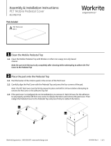
<Front View>
<Top View>
<Bottom View>
MAJOR OPERATING CONTROLS AND THEIR FUNCTIONS

-7-
1. Lens Mount
1/2" standard bayonet type lens or a microscope
adaptor can be mounted.
2. Mounting Hole
A screw hole (1/4” - 20 UNC) for mounting the camera
on a wall, ceiling with a mounting bracket or tripod.
3. Page Switch (PAGE)
A menu will appear on the monitor screen when this
switch is pressed for around 2 seconds. Pressing the
switch advances the menu page.
4. Item Switch (ITEM/AWC)
Any of the items shown in the menu can be selected
with this switch. When the menu is not displayed or
the camera is in shooting mode, the automatic white
balance control can be set with this switch.
5. Up Switch (UP/ABC)
While the menu is displayed, any setting can be
brought up to a higher value with this switch. When
the menu is not displayed or the camera is in shooting
mode, the automatic black balance control can be set
with this switch.
6. Down Switch (DOWN/BAR)
While the menu is displayed any setting can be
brought down to a lower value with this switch. When
the menu is not displayed or the camera is in shooting
mode, the color bar and the shooting conditions are
alternately indicated by pressing the switch.
ZOOM/FOCUS
REMOTE
EXT DC IN
PAGE
ITEM
(AWC)
UP
(ABC)
DOWN
(BAR)
IRIS
SEE MANUAL
CAUTION
CONNECT TO SPECIFIED
CLASS 2 POWER SUPPLY
ONLY SEE MANUAL
VBS/HD
75 
VD
VIDEO/RGB
CONTROL
VIDEO OUTG/L IN
ON
OFF
4
3
5
6
7
8
9
!0
!1
!2
!3
!4
!5
!6
!7

-8-
7. Video Output Connector (VIDEO OUT)
A composite video signal is provided at this connec-
tor.
8. Iris Connector (IRIS)
Input terminal for lens with an iris control function.
Some lenses may require an optional lens extension
cable for connection.
9. Zoom/Focus Connector (ZOOM/FOCUS)
Input terminal for lens with zoom and focus function
that can be remote controlled.
Pin No. Signal Pin No. Signal
1 Not Used 7 Iris F
2 Not Used 8 Auto/Remote Control
3 GND 9 Not Used
4 Auto/Manual Control 10 Not Used
5 Iris Control 11 Not Used
6 Lens P 12 Not Used
<Front View>
Iris Connector (IRIS)
Pin No. Signal Pin No. Signal
1 Not Used 7 Voltage Common
2 Not Used 8 Focus Control
3 GND 9 Zoom Control
4 Not Used 10 Not Used
5 Not Used 11 Lens +V
6 +12 V 12 Lens −V
<Front View>
Zoom/Focus Connector (ZOOM/FOCUS)
o
q
i
w
u
e
y
t
r
!2
!0
!1
o
q
iw
u
e
y
t
r
!2
!0
!1

-9-
Pin No. Signal Pin No. Signal
1 Composite Video Output 11 RCB Transmission
2 GND 12 Control (Command)
3 G/Y/Y Output 13 +9.2 V RCB
4 R/PR/C Output 14 DC 12 V Output
5 GND 15 DC 12 V Input
6 RCB Detect 16 DC 12 V Input
7 EXT SUB In 17 RCB Reception
8 B/PB Output 18 GND
9 GND 19 GND
10 G/L Input 20 Not used
<Front View>
Remote Connector (REMOTE)
<Front View>
DC Input Connector (EXT DC IN)
10. Remote Connector (REMOTE)
Input terminal dedicated to control signals from the
optional Remote Control Box (WV-CB700A) and the
Remote Control Unit (WV-RC700A).
* WV-CB700A is connected through the optional con-
version cable (WV-CA20T10).
* WV-RC700A is connected through the optional con-
version cable (WV-CA26T20).
11. Power Indicator
Red LED lamp lights to indicate that the specified DC
power is supplied to the camera.
12. DC Input Connector (EXT DC IN)
12 V DC is supplied through the 4-pin connector pro-
vided with the camera.
Pin No. Signal
1 +12 V In
2 +12 V In
3 Ground
4 Ground
o
q
i
w
u
e
yt
r
!2
!0
!1!3!4!5!6
@0!9!8!7
r
e
w
q

-10-
13. Video/RGB Output Connector (VIDEO/RGB)
Composite/Y signal, RGB/Y-C/component signal and
synchronizing signal are output from this connector.
* Refer to Page 41 for signal selection.
The optional cable WV-CA9T5 or WV-CA9T9 must be
used for connection to this connector.
Pin No. Signal Pin No. Signal
1 GND 6 SY/COMP
2 GND 7 SYNC
3 R/PR/C 8 GND
4 G/Y/Y 9 C/NC
5 B/PB/NC
<Front View>
The multiplex adaptor WV-PS550 is connected to this
connector when using a coaxial multiplex system. The
WV-RC700A and WV-PS550 can be connected with a
coaxial cable.
Pin No. Signal Pin No. Signal
1 Composite Video Output 15 Defroster Control Output
2 GND 16 Wiper Control Output
3 Not Used 17 Common
4 Not Used 18 +5.2 V Output
5 G/L Input 19 GND
6 GND 20 −5.2 V Output
7 WV-PS550 Detect 21 GND
8 PS Transmission 22 GND
9 PS Reception 23 DC 12 V Input
10 GND 24 DC 12 V Input
11 UP Control Output 25 Not Used
12 Down Control Output 26 +9.2 V Output
13 Left Control Output 27 GND
14 Right Control Output 28 GND
<Front View>
Control Connector (CONTROL)
Video/RGB Output Connector (VIDEO/RGB)
14. Control Connector (CONTROL)
Control signals for a pan/tilt unit come to this connec-
tor when a pan/tilt unit controller is connected to the
camera through the Remote Control Unit WV-RC700A
with a multicable.
⁄4⁄3⁄2⁄1⁄0.,mnbcxz
¤8¤7¤6¤5¤4¤3¤2¤1¤0⁄9⁄8⁄7⁄6⁄5
v
o
q
i
w
u
e
y
tr

-11-
15. G/L Signal 75-ohm ON/OFF Switch (75Ω ON/OFF)
A terminating switch for G/L signals at Items 16 and
17.
16. G/L VBS/HD Input Connector (G/L IN - VBS/HD)
Signals synchronized with the reference signal are to
be supplied to this connector when the camera is to
be synchronized with the reference signal. VBS/BB,
VS and HD signals are to be automatically deter-
mined.
17. G/L VD Input Connector (G/L IN - VD)
Same as Item 16 except that VD signal is to be sup-
plied when input signal at Item 16 is HD.
LENS MOUNTING
Lenses of any make can be mounted on the camera as
long as they are equipped with a 1/2” standard bayonet.
1. Mounting
Rotate the lens fixing ring knob counterclockwise and
remove the lens mount cap. Mount the lens on the
camera and rotate the lens fixing ring knob clockwise
in order to fix the lens securely. Then connect the lens
cable to the IRIS Connector on the back panel of the
camera.
* Use the lens extension cable WV-CA12T12 (6”/15cm)
if your lens cable is too short.
Lens fixing ring knob

-12-
FLANGE BACK ADJUSTMENT
1. Fully open the iris by shooting a dark object. (Iris
selection switch should be set to M.)
2. Loosen the flange back lock knob.
3. Aim the camera at any object over 2 meters away from
the camera.
4. Set the lens to its TELE end first and adjust its focus
with the focus ring.
5. Set the lens to its widest angle next and adjust its
focus with the flange back adjust ring.
6. Adjust the focus ring and the flange back adjust ring
alternately for the best focus within the zooming
range.
Tighten the flange back lock knob upon completion of
focusing.
7. Turn the iris selection switch to Position A.
* The figure represents Lens PH15X7BKRS2U.
IRIS GAIN CONTROL IN A LENS
An iris gain control hole is usually provided in the front of a
lens. Adjustment of the iris gain, with a screwdriver
through the hole may be done as follows. (Shape and
location of the hole may vary depending on the lens
make.)
1 Turn the iris selection switch to Position A (AUTO).
2 Rotate the iris gain control to the maximum gain but in
a range where no hunting or oscillating of the iris ring
develops.
* The figure represents Lens PH15X7BKRS2U.
Flange back
adjust ring
Flange back
lock knob
Focus ring
Iris gain control
Automatic iris power zoom lens

ZOOM/FOCUS
REMOTE
EXT DC IN
PAGE
ITEM
(AWC)
UP
(ABC)
DOWN
(BAR)
IRIS
SEE MANUAL
CAUTION
CONNECT TO SPECIFIED
CLASS 2 POWER SUPPLY
ONLY SEE MANUAL
VBS/HD
75 
VD
VIDEO/RGB
CONTROL
VIDEO OUTG/L IN
ON
OFF
-13-
■ CONNECTION OF DEVICE WITH A COMPOSITE INPUT CONNECTOR
CONNECTIONS
Caution :
The connection and installation should be done by qualified service personnel or system installers.
Refer any servicing to qualified service personnel.
1. Connect this to a 12V DC class 2 power supply only.
2. To prevent fire or shock hazard, the UL listed wire VW-1, style 1007 should be used as for the cable for 12V DC Input
Connector.
Cautions
• Connection to any device which
has a composite input connec-
tor, such as a video monitor or
a VCR, must be made through
the VIDEO OUT Connector.
• Power supply to the camera
must be through the optional
Conversion Cable WV-CA4C4P
or a power cable assembled
with the connector provided
with the camera.
• Power source must be able to
continuously supply 12 V DC,
2A nominally.
VIDEO OUT
Connector
Power supply:
12 V DC, 2A min.
Video monitor
Conversion Cable WV-CA4C4P
VIDEO IN
To AG-B640
or AU-B110
or
75Ω coaxial cable
Power Cable (locally purchased)

-14-
How to assemble the power cable:
The power cable is to be assembled with the connector
provided with the camera.
<Connector pin layout>
1. Prepare the wire.
2. Fix with a screw if necessary.
Put the casing and the rubber bushing on after solder-
ing wires to the connector.
Caution :
To prevent fire or shock hazard, the UL listed wire VW-
1, style 1007 should be used as for the cable for 12V
DC Input Connector.
1
2
4
3
<Wire view>
AWG24 or larger
3/16"
(5 mm)

-15-
Input signals to an RGB monitor or image processor must
be supplied from the VIDEO/RGB connector through the
optional D Sub/BNC cable WV-CA9T5 or D Sub/D Sub
cable WV-CA9T9.
NOTES:
• Output signals at the VIDEO/RGB connector can be
selected from the INITIAL SET menu.
• SYNC level can be selected from the INITIAL SET
menu.
■ CONNECTION OF DEVICE WITH AN RGB MONITOR OR AN IMAGE PROCESSOR
Pin Wire's Output
No. Color Signal
3 Red R/PR/C
4 Green G/Y/Y
5 Blue B/PB
6 White Y/COMP
7 Black SYNC
WV-CA9T5 Cable Information
1. Connect this to a 12V DC class 2 power supply only.
2. To prevent fire or shock hazard, the UL listed wire VW-1, style 1007 should be used as for the cable for 12V DC Input
Connector.
Cautions
ZOOM/FOCUS
REMOTE
EXT DC IN
PAGE
ITEM
(AWC)
UP
(ABC)
DOWN
(BAR)
IRIS
SEE MANUAL
CAUTION
CONNECT TO SPECIFIED
CLASS 2 POWER SUPPLY
ONLY SEE MANUAL
VBS/HD
75 
VD
VIDEO/RGB
CONTROL
VIDEO OUTG/L IN
ON
OFF
RGB monitor or
image processing
device
Red
Green
Blue
Black
White
WV-CA9T5
WV-CA9T9
or
Power supply:
12 V DC, 2A min.
Computer
RGB/SYNC
connector
RGB/SYNC
connector
Conversion Cable WV-CA4C4P
To AG-B640 or AU-B110
or
Power Cable (locally purchased)

-16-
Connection to the RCU (WV-RC700A) is made through the
optional conversion cable WV-CA26T20 and a studio
cable.
1. Turn RCU power off before connecting cables.
2. Set the cable selection switch of the RCU to MULTI.
3. Connect the 20 pin connector of the conversion cable
to the REMOTE Connector of the camera. The conver-
sion cable and the studio cable must be connected
with the connector supplied as a standard accessory
with the conversion cable.
4. Turn RCU power on and the power indicator lamp will
light. The camera can now be remote controlled by
the RCU.
NOTES:
• Maximum extension length: 300 meters
(Studio cables must be connected with joint adaptor
WV-CA26T26.)
• Use only the specified cables.
■ CONNECTION OF A REMOTE CONTROLLER (RCU AND A STUDIO CABLE)
GEN-LOCK
IN
AUX
IN
AUTO
75 ¶/Hi-Z
AUTO
75 ¶/Hi-Z
R/PR /C
OUT OUT
AUDIO
SEE MANUAL
VIDEO 1
G/Y/Y VIDEO 2
B/PB /B SYNC
S-VIDEO
1 4
2 3
TALLY
CAMERA (MULTI)
CABLE SELECT
FUSE
125V 2A
TALK
INCOM
RECEIVE
CONTROL
TALLY & INCOM
MULTI OVP
MPX
MPX
OUTPUT
ZOOM/FOCUS
REMOTE
EXT DC IN
PAGE
ITEM
(AWC)
UP
(ABC)
DOWN
(BAR)
IRIS
SEE MANUAL
CAUTION
CONNECT TO SPECIFIEDCONNECT TO SPECIFIED
CLASS 2 POWER SUPPLYCLASS 2 POWER SUPPLY
ONLY SEE MANUALONLY SEE MANUAL
VBS/HD
75 
VD
VIDEO/RGB
CONTROL
VIDEO OUTG/L IN
ON
OFF
Connector supplied
with WV-CA26T20
Studio cable (Option)
WV-CA26U15 (50 ft/15 m)
WV-CA26U30 (100 ft/30 m)
WV-CA26U100 (330 ft/100 m)
Set to MULTI
WV-RC700A
Conversion cable (Option)
WV-CA26T20 (10 ft/3 m)

-17-
■ CONNECTION OF A REMOTE CONTROLLER (RCU AND A COAXIAL MULTIPLEX SYSTEM)
The optional multiplex adaptor WV-PS550 is used for
connection of a coaxial multiplex system.
1. Turn RCU power off before connecting cables.
2. Connect the optional multiplex adaptor WV-PS550 to
the control connector of the camera through the stan-
dard accessory cable supplied with the WV-PS550.
3. Set the cable selection switch of the RCU to VP.
4. Connect the MPX connector of the multiplex adaptor
and that of the RCU with a coaxial cable (Belden 8281
or equivalent).
5. Turn RCU power on and the power indicator lamp will
light. The camera can now be remote controlled by
the RCU.
NOTES:
• Use only model WV-RC700A (with WV-CB700A) as an
RCU.
• A coaxial multiplex system cannot be used with a stu-
dio 26-pin cable.
• R/G/B, Y/C and Y/PR/PB signals cannot be transmitted
through this system. Use a studio cable if any of
these signals is required.
• The maximum cable extension length allowed for this
system is 300 meters.
GEN-LOCK
IN
AUX
IN
AUTO
75 ¶/Hi-Z
AUTO
75 ¶/Hi-Z
R/PR /C
OUT OUT
AUDIO
SEE MANUAL
VIDEO 1
G/Y/Y VIDEO 2
B/PB /B SYNC
S-VIDEO
14
23
TALLY
CAMERA (MULTI)
CABLE SELECT
FUSE
125V 2A
TALK
INCOM
RECEIVE
CONTROL
TALLY & INCOM
MULTI OVP
MPX
MPX
OUTPUT
ZOOM/FOCUS
REMOTE
EXT DC IN
PAGE
ITEM
(AWC)
UP
(ABC)
DOWN
(BAR)
IRIS
SEE MANUAL
CAUTION
CONNECT TO SPECIFIED
CLASS 2 POWER SUPPLY
ONLY SEE MANUAL
VBS/HD
75 
VD
VIDEO/RGB
CONTROL
VIDEO OUTG/L IN
ON
OFF
AUDIO
CONTROL OUTCAMERA
MPX DATA IN AUDIO IN
DATA
Supplied with
WV-PS550
multiplex adaptor WV-PS550
Set to VP
WV-RC700A
Coaxial cable
(Belden 8281 or equivalent)

ALL 1
2
USER SET
ZOOM/FOCUS
REMOTE
EXT DC IN
PAGE
ITEM
(AWC)
UP
(ABC)
DOWN
(BAR)
IRIS
SEE MANUAL
CAUTION
CONNECT TO SPECIFIED
CLASS 2 POWER SUPPLY
ONLY SEE MANUAL
VBS/HD
75 
VD
VIDEO/RGB
CONTROL
VIDEO OUTG/L IN
ON
OFF
-18-
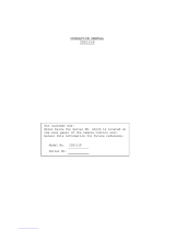
■ CONNECTION OF A REMOTE CONTROL BOX (RCB)
The RCB (WV-CB700A) and the camera must be connect-
ed with the optional conversion cable WV-CA20T10.
1. Turn RCB power off before connecting cables.
2. Connect the 20 pin connector of the conversion cable
to REMOTE connector of the camera. The 10-pin con-
nector must be connected to the RCB accessory
cable or an optional RCB cable.
3. Turn RCB power on and the camera can be remote
controlled by the RCB.
NOTES:
• The monitor output signals of the RCB attenuate and
deteriorate with cable length. It is recommended that
the signals from the monitor output be used for moni-
toring purpose only.
• No gen-lock signal is available from the RCB.
Power supply:
12 V DC, 2A min.
Video signals
RCB, Rear view
The RCB accessory cable, WV-CA10B25
(80 ft/25 m) or WV-CA10B50 (160 ft/50 m).
WV-CB700A
1. Connect this to a 12V DC class 2 power supply only.
2. To prevent fire or shock hazard, the UL listed wire VW-1,
style 1007 should be used as for the cable for 12V DC
Input Connector.
Cautions
Conversion Cable WV-CA4C4P
To AG-B640
or AU-B110
or
Power Cable (locally purchased)
Conversion cable
WV-CA20T10 (Option)
(3 ft/ 1m)
Page is loading ...
Page is loading ...
Page is loading ...
Page is loading ...
Page is loading ...
Page is loading ...
Page is loading ...
Page is loading ...
Page is loading ...
Page is loading ...
Page is loading ...
Page is loading ...
Page is loading ...
Page is loading ...
Page is loading ...
Page is loading ...
Page is loading ...
Page is loading ...
Page is loading ...
Page is loading ...
Page is loading ...
Page is loading ...
Page is loading ...
Page is loading ...
Page is loading ...
Page is loading ...
Page is loading ...
Page is loading ...
Page is loading ...
Page is loading ...
Page is loading ...
Page is loading ...
Page is loading ...
Page is loading ...
Page is loading ...
Page is loading ...
Page is loading ...
Page is loading ...
Page is loading ...
Page is loading ...
Page is loading ...
Page is loading ...
Page is loading ...
/