Anritsu 682XXB User manual
- Category
- Power generators
- Type
- User manual
This manual is also suitable for

SERIES
682XXB/683XXB
SYNTHESIZED SIGNAL GENERATORS
MAINTENANCE MANUAL
P/N: 10370-10290
REVISION: H
PRINTED: AUGUST 2003
COPYRIGHT 2003 ANRITSU CO.
490 JARVIS DRIVE
MORGAN HILL, CA 95037-2809

WARRANTY
The ANRITSU product(s) listed on the title page is (are) warranted against defects in materials and
workmanship for one year from the date of shipment.
ANRITSU’s obligation covers repairing or replacing products which prove to be defective during the
warranty period. Buyers shall prepay transportation charges for equipment returned to ANRITSU
for warranty repairs. Obligation is limited to the original purchaser. ANRITSU is not liable for con
-
sequential damages.
LIMITATION OF WARRANTY
The foregoing warrantydoes not applyto ANRITSU connectors that have failed due to normal wear.
Also, the warranty does not apply to defects resulting from improper or inadequate maintenance by
the Buyer, unauthorized modification or misuse, or operation outside of the environmental specifi-
cations of the product. No other warranty is expressed or implied, and the remedies provided herein
are the Buyer’s sole and exclusive remedies.
TRADEMARK ACKNOWLEDGEMENTS
Adobe Acrobat is a registered trademark of Adobe Systems Incorporated.
NOTICE
ANRITSU Company has prepared this manual for use by ANRITSU Company personnel and cus
-
tomers as a guide for the proper installation, operation, and maintenance of ANRITSU Company
equipment and computor programs. The drawings, specifications, and information contained herein
are the property of ANRITSU Company, and any unauthorized use or disclosure of these drawings,
specifications, and information is prohibited; they shall not be reproduced, copied, or used in whole
or in part as the basis for manufacture or sale of the equipment or software programs without the
prior writtten consent of ANRITSU Company.


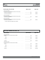
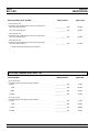
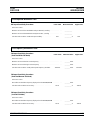
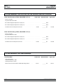
Table Of Contents
Chapter 1 - General Information
1-1 SCOPE OF MANUAL
.................
1-3
1-2 INTRODUCTION
...................
1-3
1-3 DESCRIPTION
....................
1-3
1-4 IDENTIFICATION NUMBER
............
1-5
1-5 ELECTRONIC MANUAL
...............
1-6
1-6 RELATED MANUALS
................
1-6
Operation Manual
................
1-6
GPIB Programming Manual
...........
1-6
SCPI Programming Manual
...........
1-6
1-7 OPTIONS .......................1-7
1-8 LEVEL OF MAINTENANCE.............1-8
Troubleshooting .................1-8
Repair......................1-8
Calibration ...................1-8
Preventive Maintenance .............1-8
1-9 PREVENTIVE MAINTENANCE...........1-9
1-10 STATIC-SENSITIVE COMPONENT HANDLING
PRECAUTIONS ...................1-9
1-11 STARTUP CONFIGURATIONS
...........
1-11
1-12 RECOMMENDED TEST EQUIPMENT
......
1-12
1-13 EXCHANGE ASSEMBLY PROGRAM
.......
1-14
1-14 REPLACEABLE SUBASSEMBLIES AND PARTS 1-14
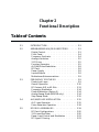
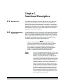
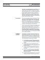
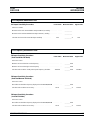
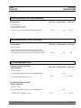
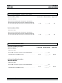
Chapter 2 - Functional Description
2-1 INTRODUCTION
...................
2-3
2-2 682XXB/683XXB MAJOR SUBSYSTEMS
......
2-3
Digital Control
..................
2-3
Front Panel
...................
2-4
Frequency Synthesis
...............
2-4
Analog Instruction
................
2-5
YIG Driver
...................
2-5
Function Generator
...............
2-5
682XXB/683XXB MM i

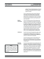
ALC/AM/Pulse Modulation
............
2-8
RF Deck
.....................
2-8
Power Supply
..................
2-8
Inputs/Outputs
.................
2-8
Motherboard/Interconnections
..........
2-9
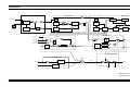
2-3 FREQUENCY SYNTHESIS
.............
2-9
Phase-Lock Loops
................
2-9
Overall Operation
...............
2-10
RF Outputs 0.01 to 65 GHz
...........
2-13
Frequency Modulation
.............
2-14
Phase Modulation (Option 6)
..........
2-14
Analog Sweep Mode (683XXB only)
.......
2-14
Step Sweep Mode
................
2-15
2-4 ALC/AM/PULSE MODULATION ..........2-15
ALC Loop Operation ..............2-15
Pulse Generator Operation ...........2-18
2-5 RF DECK ASSEMBLIES ..............2-19
RF Deck Configurations ............2-20
YIG-tuned Oscillator ..............2-20
Power Level Control and Modulation ......2-23
RF Signal Filtering...............2-23
0.01 to 2 GHz Down Converter .........2-24
0.5 to 2.2 GHz Digital Down Converter .....2-25
Switched Doubler Module
............
2-26
Source Quadrupler Module
...........
2-29
Power Level Detection/ALC Loop
........
2-30
Step Attenuator
................
2-31
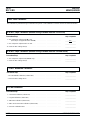
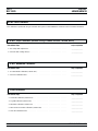
Chapter 3 - Performance Verification
3-1 INTRODUCTION
...................
3-3
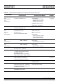
3-2 RECOMMENDED TEST EQUIPMENT
.......
3-3
3-3 TEST RECORDS
...................
3-3
3-4 CONNECTOR AND KEY LABEL NOTATION
...
3-3
3-5 682XXB/683XXB POWER LEVELS
.........
3-6
3-6 INTERNAL TIME BASE AGING RATE TEST
...
3-8
Test Setup
....................
3-8
Test Procedure
..................
3-9
ii 682XXB/683XXB MM
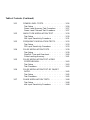
Table of Contents (Continued)

3-7 FREQUENCY SYNTHESIS TESTS
........
3-11
Test Setup
...................
3-11
Coarse Loop/YIG Loop Test Procedure
......
3-12
Fine Loop Test Procedure
............
3-13
3-8 SPURIOUS SIGNALS TEST: RF OUTPUT SIGNALS
£2 GHz (£2.2 GHz for 68XX5B MODELS)
.....
3-14
Test Setup
...................
3-14
0.01 - 2 GHz Test Procedure
..........
3-14
0.5 - 2.2 GHz Test Procedure
..........
3-17
3-9 HARMONIC TEST: RF OUTPUT SIGNALS
FROM2TO20GHz
................
3-18
Test Setup
...................
3-18
Test Procedure (2 to 10 GHz)
..........
3-19
Test Procedure (11 to 20 GHz)
.........
3-20
3-10 SINGLE SIDEBAND PHASE NOISE TEST ....3-22
Test Setup ...................3-22
Test Procedure .................3-23
3-11 POWER LEVEL ACCURACY AND FLATNESS
TESTS........................3-26
Test Setup ...................3-26
Power Level Accuracy Test Procedure ......3-27
Power Level Flatness Test Procedure ......3-27
3-12 AMPLITUDE MODULATION TEST ........3-30
Test Setup
...................
3-30
AM Input Sensitivity Procedure
.........
3-31
3-13 FREQUENCY MODULATION TESTS
.......
3-33
Test Setup
...................
3-33
FM Input Sensitivity Procedure
.........
3-33
3-14 PULSE MODULATION TESTS: RISE TIME,
FALL TIME, OVERSHOOT, AND LEVEL
....
3-39
Test Setup
...................
3-39
Rise/Fall Time and Overshoot
..........
3-40
Pulse Leveling Accuracy
............
3-41
3-15 PULSE MODULATION TEST: VIDEO
FEEDTHROUGH
..................
3-43
Test Setup
...................
3-43
Test Procedure
.................
3-44
682XXB/683XXB MM iii
Table of Contents (Continued)

3-16 PULSE MODULATION TEST: RF ON/OFF RATIO 3-45
Test Setup
...................
3-45
Test Procedure
.................
3-45
3-17 PHASE MODULATION TESTS
...........
3-48
Test Setup
...................
3-48
FM Input Sensitivity Procedure
.........
3-48
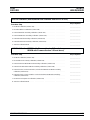
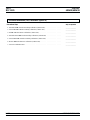
Chapter 4 - Calibration
4-1 INTRODUCTION
...................
4-3
4-2 RECOMMENDED TEST EQUIPMENT
.......
4-3
4-3 TEST RECORDS
...................
4-3
4-4 CALIBRATION FOLLOWING SUBASSEMBLY
REPLACEMENT...................4-4
4-5 CONNECTOR AND KEY LABEL NOTATION . . . 4-4
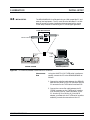
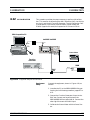
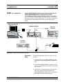
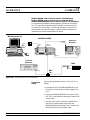
4-6 INITIAL SETUP....................4-7
Interconnection .................4-7
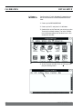
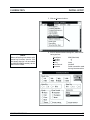
PC Setup — Windows 3.1 ............4-8
PC Setup — Windows 95 ............4-10
4-7 PRELIMINARY CALIBRATION ..........4-13
Equipment Setup................4-13
Calibration Steps................4-14
4-8 SWITCHED FILTER SHAPER CALIBRATION
..
4-17
Equipment Setup
................
4-17
Log Amplifier Zero Calibration
.........
4-18
Limiter DAC Adjustment
............
4-18
Shaper DAC Adjustment
............
4-19
4-9 RF LEVEL CALIBRATION
.............
4-22
4-10 ALC SLOPE CALIBRATION
............
4-23
Equipment Setup
................
4-23
ALC Slope DAC Adjustment
..........
4-24
4-11 ALC BANDWIDTH CALIBRATION
........
4-31
Equipment Setup
................
4-31
Bandwidth Calibration
.............
4-31
iv 682XXB/683XXB MM
Table of Contents (Continued)

4-12 AM CALIBRATION
.................
4-33
Equipment Setup
................
4-33
AM Calibration Procedure
...........
4-34
4-13 FM CALIBRATION
.................
4-37
Equipment Setup
................
4-37
FM Calibration Procedure
...........
4-38
4-14 PHASE MODULATION (FM) CALIBRATION
...
4-51
Equipment Setup
................
4-51
FM Calibration Procedure
...........
4-52
Chapter5-Troubleshooting
5-1 INTRODUCTION
...................
5-3
5-2 RECOMMENDED TEST EQUIPMENT
.......
5-3
5-3 ERROR AND WARNING/STATUS MESSAGES. . . 5-3
Self-Test Error Messages.............5-3
Normal Operation Error and Warning/
Status Messages ................5-7
5-4 MALFUNCTIONS NOT DISPLAYING AN ERROR
MESSAGE .....................5-10
5-5 TROUBLESHOOTING TABLES ..........5-10
Chapter 6 - Removal and Replacement Procedures
6-1 INTRODUCTION
...................
6-3
6-2 REMOVING AND REPLACING THE CHASSIS
COVERS
.......................
6-4
Preliminary
...................
6-4
Procedure
....................
6-4
6-3 REMOVING AND REPLACING THE FRONT
PANEL ASSEMBLY
.................
6-6
Preliminary
...................
6-6
Procedure
....................
6-6
6-4 REMOVING AND REPLACING THE A3, A4, A5,
OR A6 PCB
......................
6-8
Preliminary
...................
6-8
Procedure
....................
6-8
682XXB/683XXB MM v
Table of Contents (Continued)

6-5 REMOVING AND REPLACING THE A7 PCB
...
6-10
Preliminary
..................
6-10
Procedure
...................
6-10
6-6 REMOVING AND REPLACING THE A8, A9, A10,
A11, OR A12 PCB
..................
6-10
Preliminary
..................
6-10
Procedure
...................
6-10
6-7 REMOVING AND REPLACING THE A13, A14,
OR A15 PCB
....................
6-11
Preliminary
...................
6-11
Procedure
...................
6-11
6-8 REMOVING AND REPLACING THE A16
OR A17 PCB
....................
6-11
Preliminary...................6-11
Procedure ...................6-11
6-9 REMOVING AND REPLACING THE A18
ORA19PCB....................6-12
Preliminary ..................6-12
Procedure ...................6-12
6-10 REMOVING AND REPLACING THE REAR
PANEL ASSEMBLY ................6-13
Preliminary ..................6-13
Procedure
...................
6-13
6-11 REMOVING AND REPLACING THE A21 PCB
..
6-16
Preliminary
..................
6-16
Procedure
...................
6-16
6-12 REMOVING AND REPLACING THE A21-1 PCB
.
6-17
Preliminary
..................
6-17
Procedure
...................
6-17
6-13 REMOVING AND REPLACING THE FAN
ASSEMBLY
.....................
6-18
Preliminary
..................
6-18
Procedure
...................
6-18
Appendix A - Test Records
A-1 INTRODUCTION
...................
A-1
vi 682XXB/683XXB MM
Table of Contents (Continued)

Table of Contents
1-1 SCOPE OF MANUAL
.................
1-3
1-2 INTRODUCTION
...................
1-3
1-3 DESCRIPTION
....................
1-3
1-4 IDENTIFICATION NUMBER
............
1-5
1-5 ELECTRONIC MANUAL...............1-6
1-6 RELATED MANUALS ................1-6
Operation Manual ................1-6
GPIB Programming Manual ...........1-6
SCPI Programming Manual ...........1-6
1-7 OPTIONS .......................1-7
1-8 LEVEL OF MAINTENANCE.............1-8
Troubleshooting .................1-8
Repair
......................
1-8
Calibration
...................
1-8
Preventive Maintenance
.............
1-8
1-9 PREVENTIVE MAINTENANCE
...........
1-9
1-10 STATIC-SENSITIVE COMPONENT HANDLING
PRECAUTIONS
...................
1-9
1-11 STARTUP CONFIGURATIONS
...........
1-11
1-12 RECOMMENDED TEST EQUIPMENT
......
1-12
1-13 EXCHANGE ASSEMBLY PROGRAM
.......
1-14
1-14 REPLACEABLE SUBASSEMBLIES AND PARTS 1-15
Chapter 1
General Information

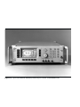
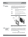
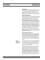
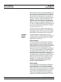
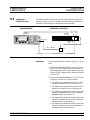
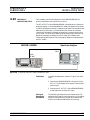
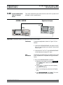
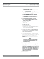
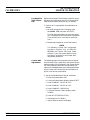
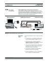
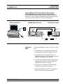
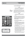
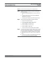
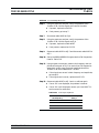
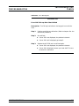
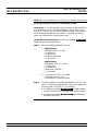
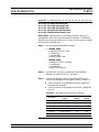
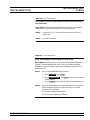
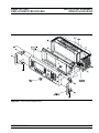
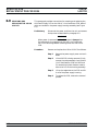
Figure 1-1. Typical Series 682XXB/683XXB Synthesized Signal Generator (Model 68369B Shown)

Chapter 1
General Information
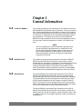
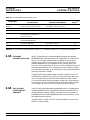
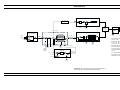
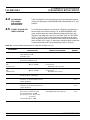
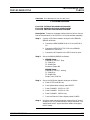
1-1 SCOPE OF MANUAL This manual provides service information for all models of the Series
682XXB/683XXB Synthesized Signal Generators. The service informa
-
tion includes replaceable parts information, functional circuit descrip
-
tions, block diagrams, performance verification tests, and procedures
for calibration, troubleshooting, and assembly/subassembly removal
and replacement. (Throughout this manual, the terms 682XXB/
683XXB and signal generator will be used interchangeably to refer to
the instrument.) Manual organization is shown in the table of con
-
tents.
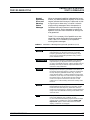
NOTE
Service information for the series 682XXB signal generators
and series 683XXB signal generators is combined into one
manual because identical model numbers of each series con-
tain the same assemblies, subassemblies, and components.
Differences between the series are noted where applicable
throughout the manual.
1-2 INTRODUCTION This chapter provides a general description of the Series 682XXB/
683XXB Synthesized Signal Generators, identification numbers,
related manuals, and options. Information is included concerning level
of maintenance, replaceable subassemblies and RF components,
exchange assembly program, and preventive maintenance. Static-
sensitive component handling precautions and lists of exchangeable
subassemblies and recommended test equipment are also provided.
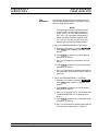
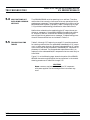
1-3 DESCRIPTION The Series 682XXB Synthesized Signal Generator and the Series
683XXB Synthesized Signal Generator are microprocessor-based,
synthesized signal sources with high resolution phase-lock capability.
They generate both discrete CW frequencies and broad (full range)
and narrow band sweeps across the frequency range of 10 MHz to
65 GHz. All functions of the signal generators are fully controllable
locally from the front panel or remotely (except for power on/standby)
via the IEEE-488 General Purpose Interface Bus (GPIB).
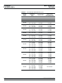
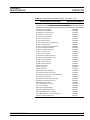
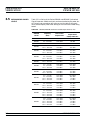
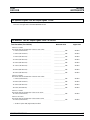
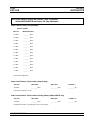
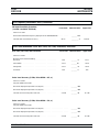
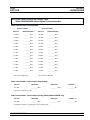
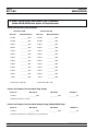
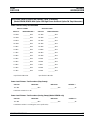
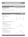
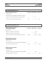
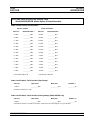
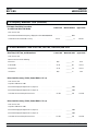
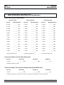
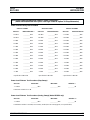
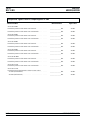
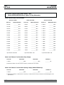
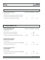
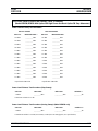
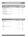
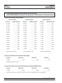
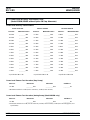
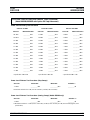
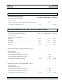
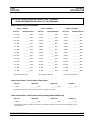
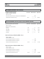
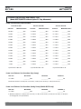
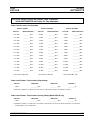
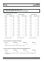
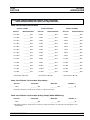
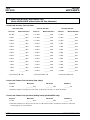
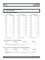
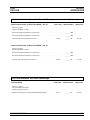
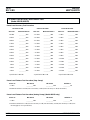
The Series 682XXB Synthesized Signal Generator and the Series
683XXB Synthesized Signal Generator each presently consists of 15
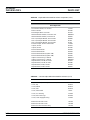
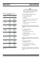
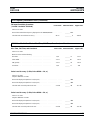
models covering a variety of frequency ranges and power levels. Table
1-1, pages 1-4 and 1-5, lists models, frequency ranges, and maximum
leveled output.
682XXB/683XXB MM 1-3

1-4 682XXB/683XXB MM
GENERAL 682XXB/683XXB
INFORMATION MODELS
68XXXB
Model
Frequency
(GHz)
Output Power
Output Power
w/Step Attenuator
68X37B 2.0 – 20.0 GHz +13.0 dBm +11.0 dBm
68X45B 0.5 – 20.0 GHz +13.0 dBm +11.0 dBm
68X47B 0.01 – 20.0 GHz +13.0 dBm +11.0 dBm
68X53B
2.0 – 20.0 GHz
20.0 – 26.5 GHz
+9.0 dBm
+6.0 dBm
+7.0 dBm
+3.5 dBm
68X55B
0.5 – 2.2 GHz
2.2 – 20.0 GHz
20.0 – 26.5 GHz
+13.0 dBm
+9.0 dBm
+6.0 dBm
+11.0 dBm
+7.0 dBm
+3.5 dBm
68X59B
0.01 – 2.0 GHz
2.0 – 20.0 GHz
20.0 – 26.5 GHz
+13.0 dBm
+9.0 dBm
+6.0 dBm
+11.0 dBm
+7.0 dBm
+3.5 dBm
68X63B
2.0 – 20.0 GHz
20.0 – 40.0 GHz
+9.0 dBm
+6.0 dBm
+7.0 dBm
+3.0 dBm
68X65B
0.5 – 2.2 GHz
2.2 – 20.0 GHz
20.0 – 40.0 GHz
+13.0 dBm
+9.0 dBm
+6.0 dBm
+11.0 dBm
+7.0 dBm
+3.0 dBm
68X69B
0.01 – 2.0 GHz
2.0 – 20.0 GHz
20.0 – 40.0 GHz
+13.0 dBm
+9.0 dBm
+6.0 dBm
+11.0 dBm
+7.0 dBm
+3.0 dBm
68X75B
0.5 – 2.2 GHz
2.2 – 20.0 GHz
20.0 – 40.0 GHz
40.0 – 50.0 GHz
+11.0 dBm
+10.0 dBm
+2.5 dBm
+2.5 dBm
+10.0 dBm
+8.5 dBm
0.0 dBm
–1.0 dBm
68X77B
0.01 – 2.0 GHz
2.0 – 20.0 GHz
20.0 – 40.0 GHz
40.0 – 50.0 GHz
+12.0 dBm
+10.0 dBm
+2.5 dBm
+2.5 dBm
+10.0 dBm
+8.5 dBm
0.0 dBm
–1.0 dBm
68X85B
0.5 – 2.2 GHz
2.2 – 20.0 GHz
20.0 – 40.0 GHz
40.0 – 50.0 GHz
50.0 – 60.0 GHz
+11.0 dBm
+10.0 dBm
+2.5 dBm
+2.0 dBm
+2.0 dBm
+10.0 dBm
+8.5 dBm
0.0 dBm
–1.5 dBm
–2.0 dBm
68X87B
0.01 – 2.0 GHz
2.0 – 20.0 GHz
20.0 – 40.0 GHz
40.0 – 50.0 GHz
50.0 – 60.0 GHz
+12.0 dBm
+10.0 dBm
+2.5 dBm
+2.0 dBm
+2.0 dBm
+10.0 dBm
+8.5 dBm
0.0 dBm
–1.5 dBm
–2.0 dBm
68X95B
0.5 – 2.2 GHz
2.2 – 20.0 GHz
20.0 – 40.0 GHz
40.0 – 50.0 GHz
50.0 – 65.0 GHz
+11.0 dBm
+10.0 dBm
+2.5 dBm
0.0 dBm
–2.0 dBm
Not Available
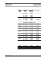
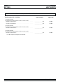
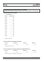
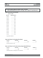
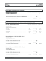
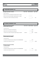
Table 1-1. Series 682XXB/683XXB Models (1 of 2)

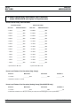
1-4 IDENTIFICATION
NUMBER
All ANRITSU instruments are assigned a unique six-digit ID number,
such as “403002.” The ID number is imprinted on a decal that is af
-
fixed to the rear panel of the unit. Special-order instrument configura
-
tions also have an additional special serial number tag attached to the
rear panel of the unit.
682XXB/683XXB MM 1-5
GENERAL IDENTIFICATION
INFORMATION NUMBER
68XXXB
Model
Frequency
(GHz)
Output Power
Output Power
w/Step Attenuator
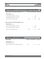
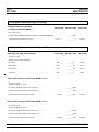
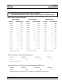
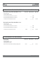
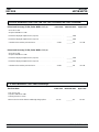
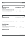
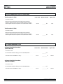
68X97B
0.01 – 2.0 GHz
2.0 – 20.0 GHz
20.0 – 40.0 GHz
40.0 – 50.0 GHz
50.0 – 65.0 GHz
+12.0 dBm
+10.0 dBm
+2.5 dBm
0.0 dBm
–2.0 dBm
Not Available
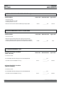
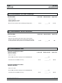
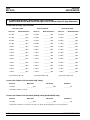
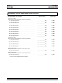
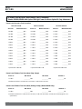
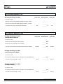
With Option 15B (High Power) Installed
68X37B 2.0 – 20.0 GHz +17.0 dBm +15.0 dBm
68X45B
0.5 – 2.2 GHz
2.2 – 20.0 GHz
+13.0 dBm
+17.0 dBm
+11.0 dBm
+15.0 dBm
68X47B
0.01 – 2.0 GHz
2.0 – 20.0 GHz
+13.0 dBm
+17.0 dBm
+11.0 dBm
+15.0 dBm
68X53B
2.0 – 20.0 GHz
20.0 – 26.5 GHz
+13.0 dBm
+10.0 dBm
+11.0 dBm
+7.5 dBm
68X55B
0.5 – 2.2 GHz
2.2 – 20.0 GHz
20.0 – 26.5 GHz
+13.0 dBm
+13.0 dBm
+10.0 dBm
+11.0 dBm
+11.0 dBm
+7.5 dBm
68X59B
0.01 – 2.0 GHz
2.0 – 20.0 GHz
20.0 – 26.5 GHz
+13.0 dBm
+13.0 dBm
+10.0 dBm
+11.0 dBm
+11.0 dBm
+7.5 dBm
68X63B
2.0 – 20.0 GHz
20.0 – 40.0 GHz
+13.0 dBm
+6.0 dBm
+11.0 dBm
+3.0 dBm
68X65B
0.5 – 2.2 GHz
2.2 – 20.0 GHz
20.0 – 40.0 GHz
+13.0 dBm
+13.0 dBm
+6.0 dBm
+11.0 dBm
+11.0 dBm
+3.0 dBm
68X69B
0.01 – 2.0 GHz
2.0 – 20.0 GHz
20.0 – 40.0 GHz
+13.0 dBm
+13.0 dBm
+6.0 dBm
+11.0 dBm
+11.0 dBm
+3.0 dBm
68X75B 0.5 – 50.0 GHz Standard Standard
68X77B 0.01 – 50.0 GHz Standard Standard
68X85B 0.5 – 60.0 GHz Standard Standard
68X87B 0.01 – 60.0 GHz Standard Standard
68X95B 0.5 - 65.0 GHz Standard Not Available
68X97B 0.01 – 65.0 GHz Standard Not Available
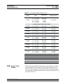
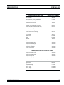
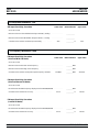
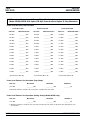
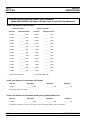
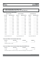
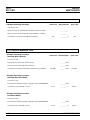
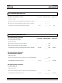
Table 1-1. Series 682XXB/683XXB Models (2 of 2)

When ordering parts or corresponding with ANRITSU Customer Serv
-
ice, please use the correct serial number with reference to the specific
instrument’s model number (i.e., Model 68347B Synthesized Signal
Generator, Serial No. 403002).
1-5 ELECTRONIC MANUAL This manual is available on CD ROM as an Adobe Acrobat Portable
Document Format (*.pdf) file. The file can be viewed using Acrobat
Reader, a free program that is also included on the CD ROM. The file
is “linked” such that the viewer can choose a topic to view from the
displayed “bookmark” list and “jump” to the manual page on which the
topic resides. The text can also be word-searched. Contact ANRITSU
Customer Service for price and availability.
1-6 RELATED MANUALS This is one of a four manual set that consists of an Operation Manual,
a GPIB Programming Manual, a SCPI Programming Manual, and a
Maintenance Manual.
Operation
Manual
This manual provides information and instructions
for operation of the series 682XXB/683XXB signal
generators using the front panel controls. It also in-
cludes general information, performance specifica-
tions, installation instructions, and operation
verification procedures. The ANRITSU part number
for the Operation Manual is 10370-10284.
GPIB
Programming
Manual
This manual provides information for remote opera-
tion of the series 682XXB/683XXB signal generators
using Product Specific commands sent from an ex
-
ternal controller via the IEEE 488 General Purpose
Interface Bus (GPIB). It contains a complete listing
and description of all 682XXB/683XXB GPIB Prod
-
uct Specific commands and several programming
examples. The ANRITSU part number for the GPIB
Programming Manual is 10370-10286.
SCPI
Programming
Manual
This manual provides information for remote opera
-
tion of the series 682XXB/683XXB signal generators
using Standard Commands for Programmable In
-
struments (SCPI) commands sent from an external
controller via the IEEE 488 General Purpose Inter
-
face Bus (GPIB). It contains a complete listing and
description of each command in the 682XXB/
683XXB SCPI command set and examples of com
-
mand usage. The ANRITSU part number for the
SCPI Programming Manual is 10370-10288.
1-6 682XXB/683XXB MM
GENERAL ELECTRONIC
INFORMATION MANUAL

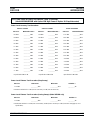
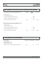
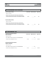
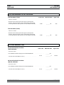
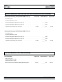
1-7 OPTIONS The following instrument options are available.
Option 1, Rack Mounting. Rack mount kit containing a set of
track slides (90° tilt capability), mounting ears, and front panel
handles for mounting the instrument in a standard 19-inch
equipment rack.
Option 2A, 110 dB Step Attenuator. Adds a 10 dB per step
attenuator with a 110 dB range for models having a high-end
frequency of £26.5 GHz. Output power is selected directly in dBm
on the front panel (or via GPIB). Rated output power is reduced.
Option 2B, 110 dB Step Attenuator. Adds a 10 dB per step
attenuator with a 110 dB range for models having a high-end
frequency of £40 GHz. Output power is selected directly in dBm
on the front panel (or via GPIB). Rated output power is reduced.
Option 2C, 90 dB Step Attenuator. Adds a 10 dB per step
attenuator with a 90 dB range for models having a high-end
frequency of £50 GHz. Output power is selected directly in dBm
on the front panel (or via GPIB). Rated output power is reduced.
Option 2D, 90 dB Step Attenuator. Adds a 10 dB per step
attenuator with a 90 dB range for models having a high-end
frequency of £60 GHz. Output power is selected directly in dBm
on the front panel (or via GPIB). Rated output power is reduced.
Option 6, Phase Modulation (FM). Adds phase modulation ca-
pability. The internal FM generator becomes the FM/FM genera-
tor. (Not available in combination with Option 7.)
Option 7, Delete AM/FM Generator. Deletes the internal AM
and FM generators. External AM and FM capability remains un
-
changed. (Not available in combination with Option 8 or Option
20.)
Option 8, Internal Power Meter. Adds an internal power
meter that is compatible with ANRITSU 560-7, 5400-71, or 6400-
71 series detectors. (Not available in combination with Option 7.)
Option 9, Rear Panel RF Output. Moves the RF output con
-
nector to the rear panel.
Option 11, 0.1 Hz Frequency Resolution. Provides frequency
resolution of 0.1 Hz.
Option 14, ANRITSU 360B VNA Compatibility. Modifies rack
mounting hardware to mate unit in a ANRITSU 360B VNA con
-
sole.
Option 15B, High Power Output. Adds high-power RF compo
-
nents to the instrument providing increased RF output power in
the 2–26.5 GHz frequency range. Option 15B is standard in mod
-
els having a high-end frequency that is >40 GHz.
Option 16, High-Stability Time Base. Adds an ovenized,
10 MHz crystal oscillator with <5 x 10
–10
/day frequency stability.
682XXB/683XXB MM 1-7
GENERAL OPTIONS
INFORMATION

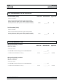
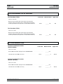
Option 17A, No Front Panel. Deletes the front panel for use in
remote control applications where a front panel display or key
-
board control are not needed.
Option 18, mmWave Module Bias Output. Provides bias out
-
put for 54000-xWRxx Millimeter Wave Source Modules. BNC
Twinax connector, rear panel.
Option 19, SCPI Programmability. Adds GPIB command
mnemonics complying with Standard Commands for Program
-
mable Instruments (SCPI), Version 1993. SCPI programming
complies with IEEE 488.2-1987.
Option 20, SCAN Modulator. Adds an internal SCAN modula
-
tor for simulating high-depth amplitude modulated signals in
models 68237B/68337B, 68245B/68345B, and 68247B/68347B
only. Requires an external modulating signal. (Not available in
combination with Option 7.)
1-8 LEVEL OF
MAINTENANCE
Maintenance of the 682XXB/683XXB consists of:
Troubleshooting the instrument to a replaceable subassembly or
RF component.
Repair by replacing the failed subassembly or RF component.
Calibration.
Preventive maintenance.
Troubleshoot-
ing
The 682XXB/683XXB firmware includes internal
diagnostics that self-test most of the internal assem-
blies of the instrument. When the signal generator
fails self-test, one or more error messages are dis
-
played to aid in troubleshooting the failure to a
replaceable subassembly or RF component. Chapter
5 lists and describes the self-test error messages
and provides procedures for isolating 682XXB/
683XXB failures to a replaceable subassembly or RF
component.
Repair Most instrument failures are field repairable by re
-
placing the failed subassembly or RF component.
Detailed instructions for removing and replacing
failed subassemblies and components are provided
in Chapter 6.
Calibration The signal generator may require calibration after
repair. Refer to Chapter 4 for a listing of calibration
requirements and calibration procedures.
Preventive
Maintenance
Preventive maintenance on the 682XXB/683XXB
consists of cleaning the fan honeycomb filter, de
-
scribed in paragraph 1-8.
1-8 682XXB/683XXB MM
GENERAL LEVEL OF
INFORMATION MAINTENANCE

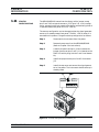
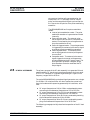
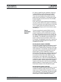
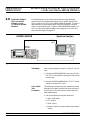
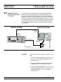
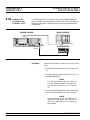
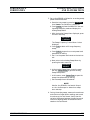
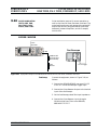
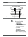
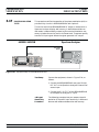
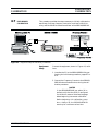
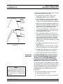
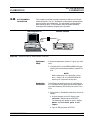
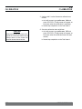
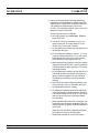
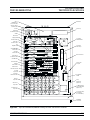
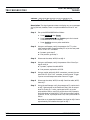
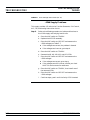
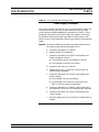
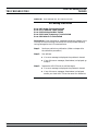
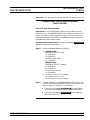
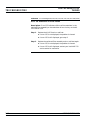
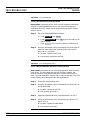
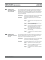
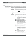
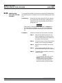
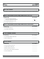
1-9 PREVENTIVE
MAINTENANCE
The 682XXB/683XXB must always receive adequate ventilation. A
blocked fan filter can cause the instrument to overheat and shut down.
Check and clean the rear panel fan honeycomb filter periodically.
Clean the fan honeycomb filter more frequently in dusty environ
-
ments. Clean the filter as follows.
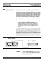
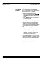
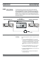
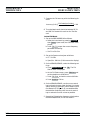
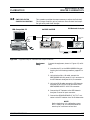
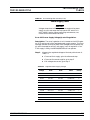
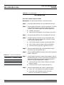
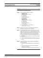
Step 1 Remove the filter guard from the rear panel by pull
-
ing out on the four panel fasteners holding them in
place (Figure 1-2).
Step 2 Vacuum the honeycomb filter to clean it.
Step 3 Install the filter guard back on the rear panel.
Step 4 Press in on the panel fasteners to secure the filter
guard to the rear panel.
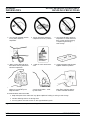
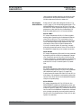
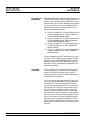
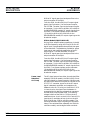
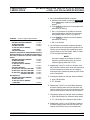
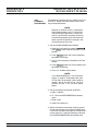
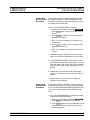
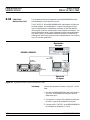
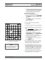
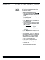
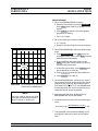
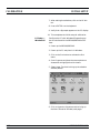
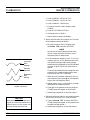
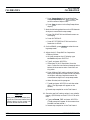
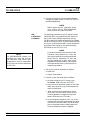
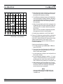
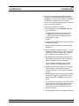
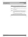
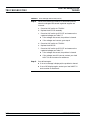
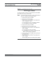
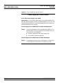
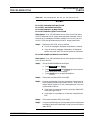
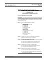
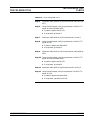
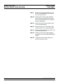
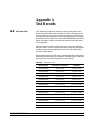
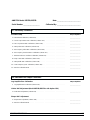
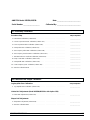
1-10 STATIC-SENSITIVE
COMPONENT
HANDLING
PRECAUTIONS
The 682XXB/683XXB contains components that can be damaged by
static electricity. Figure 1-3 illustrates the precautions that should be
followed when handling static-sensitive subassemblies and compo
-
nents. If followed, these precautions will minimize the possibilities of
static-shock damage to these items.
NOTE
Use of a grounded wrist strap when removing and/or replac
-
ing subassemblies or components is strongly recommended.
682XXB/683XXB MM 1-9
Panel
Fastener (4)
Filter
Guard
Figure 1-2. Removing/Replacing the Fan Filter Guard
GENERAL PREVENTIVE
INFORMATION MAINTENANCE

1-10 682XXB/683XXB MM
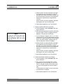
GENERAL STATIC-SENSITIVE COMPONENT
INFORMATION HANDLING PRECAUTIONS
1. Do not touch exposed contacts
on any static sensitive
component.
2. Do not slide static sensitive
component across any surface.
3. Do not handle static sensitive
components in areas where the
floor or work surface covering
is capable of generating a
static charge.
4. Wear a static-discharge wrist-
band when working with static
sensitive components.
5. Label all static sensitive de-
vices.
6. Keep component leads shorted
together whenever possible.
7. Handle PCBs only by their
edges. Do not handle by the
edge connectors.
8. Lift & handle solid state de
-
vices by their bodies – never
by their leads.
9. Transport and store PCBs and
other static sensitive devices
in static-shielded containers.
10. ADDITIONAL PRECAUTIONS:
·
Keep workspaces clean and free of any objects capable of holding or storing a static charge.
·
Connect soldering tools to an earth ground.
·
Use only special anti-static suction or wick-type desoldering tools.
Figure 1-3. Static-Sensitive Component Handling Precautions
Page is loading ...
Page is loading ...
Page is loading ...
Page is loading ...
Page is loading ...
Page is loading ...
Page is loading ...
Page is loading ...
Page is loading ...
Page is loading ...
Page is loading ...
Page is loading ...
Page is loading ...
Page is loading ...
Page is loading ...
Page is loading ...
Page is loading ...
Page is loading ...
Page is loading ...
Page is loading ...
Page is loading ...
Page is loading ...
Page is loading ...
Page is loading ...
Page is loading ...
Page is loading ...
Page is loading ...
Page is loading ...
Page is loading ...
Page is loading ...
Page is loading ...
Page is loading ...
Page is loading ...
Page is loading ...
Page is loading ...
Page is loading ...
Page is loading ...
Page is loading ...
Page is loading ...
Page is loading ...
Page is loading ...
Page is loading ...
Page is loading ...
Page is loading ...
Page is loading ...
Page is loading ...
Page is loading ...
Page is loading ...
Page is loading ...
Page is loading ...
Page is loading ...
Page is loading ...
Page is loading ...
Page is loading ...
Page is loading ...
Page is loading ...
Page is loading ...
Page is loading ...
Page is loading ...
Page is loading ...
Page is loading ...
Page is loading ...
Page is loading ...
Page is loading ...
Page is loading ...
Page is loading ...
Page is loading ...
Page is loading ...
Page is loading ...
Page is loading ...
Page is loading ...
Page is loading ...
Page is loading ...
Page is loading ...
Page is loading ...
Page is loading ...
Page is loading ...
Page is loading ...
Page is loading ...
Page is loading ...
Page is loading ...
Page is loading ...
Page is loading ...
Page is loading ...
Page is loading ...
Page is loading ...
Page is loading ...
Page is loading ...
Page is loading ...
Page is loading ...
Page is loading ...
Page is loading ...
Page is loading ...
Page is loading ...
Page is loading ...
Page is loading ...
Page is loading ...
Page is loading ...
Page is loading ...
Page is loading ...
Page is loading ...
Page is loading ...
Page is loading ...
Page is loading ...
Page is loading ...
Page is loading ...
Page is loading ...
Page is loading ...
Page is loading ...
Page is loading ...
Page is loading ...
Page is loading ...
Page is loading ...
Page is loading ...
Page is loading ...
Page is loading ...
Page is loading ...
Page is loading ...
Page is loading ...
Page is loading ...
Page is loading ...
Page is loading ...
Page is loading ...
Page is loading ...
Page is loading ...
Page is loading ...
Page is loading ...
Page is loading ...
Page is loading ...
Page is loading ...
Page is loading ...
Page is loading ...
Page is loading ...
Page is loading ...
Page is loading ...
Page is loading ...
Page is loading ...
Page is loading ...
Page is loading ...
Page is loading ...
Page is loading ...
Page is loading ...
Page is loading ...
Page is loading ...
Page is loading ...
Page is loading ...
Page is loading ...
Page is loading ...
Page is loading ...
Page is loading ...
Page is loading ...
Page is loading ...
Page is loading ...
Page is loading ...
Page is loading ...
Page is loading ...
Page is loading ...
Page is loading ...
Page is loading ...
Page is loading ...
Page is loading ...
Page is loading ...
Page is loading ...
Page is loading ...
Page is loading ...
Page is loading ...
Page is loading ...
Page is loading ...
Page is loading ...
Page is loading ...
Page is loading ...
Page is loading ...
Page is loading ...
Page is loading ...
Page is loading ...
Page is loading ...
Page is loading ...
Page is loading ...
Page is loading ...
Page is loading ...
Page is loading ...
Page is loading ...
Page is loading ...
Page is loading ...
Page is loading ...
Page is loading ...
Page is loading ...
Page is loading ...
Page is loading ...
Page is loading ...
Page is loading ...
Page is loading ...
Page is loading ...
Page is loading ...
Page is loading ...
Page is loading ...
Page is loading ...
Page is loading ...
Page is loading ...
Page is loading ...
Page is loading ...
Page is loading ...
Page is loading ...
Page is loading ...
Page is loading ...
Page is loading ...
Page is loading ...
Page is loading ...
Page is loading ...
Page is loading ...
Page is loading ...
Page is loading ...
Page is loading ...
Page is loading ...
Page is loading ...
Page is loading ...
Page is loading ...
Page is loading ...
Page is loading ...
Page is loading ...
Page is loading ...
Page is loading ...
Page is loading ...
Page is loading ...
Page is loading ...
Page is loading ...
Page is loading ...
Page is loading ...
Page is loading ...
Page is loading ...
Page is loading ...
Page is loading ...
Page is loading ...
Page is loading ...
Page is loading ...
Page is loading ...
Page is loading ...
Page is loading ...
Page is loading ...
Page is loading ...
Page is loading ...
Page is loading ...
Page is loading ...
Page is loading ...
Page is loading ...
Page is loading ...
Page is loading ...
Page is loading ...
Page is loading ...
Page is loading ...
Page is loading ...
Page is loading ...
Page is loading ...
Page is loading ...
Page is loading ...
Page is loading ...
Page is loading ...
Page is loading ...
Page is loading ...
Page is loading ...
Page is loading ...
Page is loading ...
Page is loading ...
Page is loading ...
Page is loading ...
Page is loading ...
Page is loading ...
Page is loading ...
Page is loading ...
Page is loading ...
Page is loading ...
Page is loading ...
Page is loading ...
Page is loading ...
Page is loading ...
Page is loading ...
Page is loading ...
Page is loading ...
Page is loading ...
Page is loading ...
Page is loading ...
Page is loading ...
Page is loading ...
Page is loading ...
Page is loading ...
Page is loading ...
Page is loading ...
Page is loading ...
Page is loading ...
Page is loading ...
Page is loading ...
Page is loading ...
Page is loading ...
Page is loading ...
Page is loading ...
Page is loading ...
Page is loading ...
Page is loading ...
Page is loading ...
Page is loading ...
Page is loading ...
Page is loading ...
Page is loading ...
Page is loading ...
Page is loading ...
Page is loading ...
Page is loading ...
Page is loading ...
Page is loading ...
Page is loading ...
Page is loading ...
Page is loading ...
Page is loading ...
Page is loading ...
Page is loading ...
Page is loading ...
Page is loading ...
Page is loading ...
Page is loading ...
Page is loading ...
Page is loading ...
Page is loading ...
Page is loading ...
Page is loading ...
Page is loading ...
Page is loading ...
Page is loading ...
Page is loading ...
Page is loading ...
Page is loading ...
Page is loading ...
Page is loading ...
Page is loading ...
Page is loading ...
Page is loading ...
Page is loading ...
Page is loading ...
Page is loading ...
Page is loading ...
Page is loading ...
Page is loading ...
Page is loading ...
Page is loading ...
Page is loading ...
Page is loading ...
Page is loading ...
Page is loading ...
Page is loading ...
Page is loading ...
Page is loading ...
Page is loading ...
Page is loading ...
Page is loading ...
Page is loading ...
Page is loading ...
Page is loading ...
Page is loading ...
Page is loading ...
Page is loading ...
Page is loading ...
Page is loading ...
Page is loading ...
Page is loading ...
Page is loading ...
Page is loading ...
Page is loading ...
Page is loading ...
Page is loading ...
Page is loading ...
Page is loading ...
Page is loading ...
Page is loading ...
Page is loading ...
Page is loading ...
Page is loading ...
Page is loading ...
Page is loading ...
Page is loading ...
Page is loading ...
Page is loading ...
Page is loading ...
Page is loading ...
Page is loading ...
Page is loading ...
Page is loading ...
Page is loading ...
Page is loading ...
Page is loading ...
Page is loading ...
Page is loading ...
Page is loading ...
Page is loading ...
Page is loading ...
Page is loading ...
Page is loading ...
Page is loading ...
Page is loading ...
Page is loading ...
Page is loading ...
Page is loading ...
Page is loading ...
Page is loading ...
Page is loading ...
Page is loading ...
Page is loading ...
Page is loading ...
Page is loading ...
Page is loading ...
Page is loading ...
Page is loading ...
Page is loading ...
Page is loading ...
Page is loading ...
Page is loading ...
Page is loading ...
Page is loading ...
Page is loading ...
Page is loading ...
Page is loading ...
Page is loading ...
Page is loading ...
Page is loading ...
Page is loading ...
Page is loading ...
Page is loading ...
Page is loading ...
Page is loading ...
Page is loading ...
Page is loading ...
Page is loading ...
Page is loading ...
Page is loading ...
Page is loading ...
Page is loading ...
Page is loading ...
Page is loading ...
Page is loading ...
Page is loading ...
Page is loading ...
Page is loading ...
Page is loading ...
Page is loading ...
Page is loading ...
Page is loading ...
Page is loading ...
Page is loading ...
Page is loading ...
Page is loading ...
Page is loading ...
Page is loading ...
Page is loading ...
Page is loading ...
Page is loading ...
Page is loading ...
Page is loading ...
Page is loading ...
Page is loading ...
Page is loading ...
Page is loading ...
Page is loading ...
Page is loading ...
Page is loading ...
Page is loading ...
Page is loading ...
Page is loading ...
Page is loading ...
Page is loading ...
Page is loading ...
Page is loading ...
Page is loading ...
Page is loading ...
Page is loading ...
Page is loading ...
Page is loading ...
Page is loading ...
Page is loading ...
Page is loading ...
Page is loading ...
Page is loading ...
Page is loading ...
Page is loading ...
Page is loading ...
Page is loading ...
Page is loading ...
Page is loading ...
Page is loading ...
Page is loading ...
Page is loading ...
Page is loading ...
Page is loading ...
Page is loading ...
Page is loading ...
Page is loading ...
Page is loading ...
-
 1
1
-
 2
2
-
 3
3
-
 4
4
-
 5
5
-
 6
6
-
 7
7
-
 8
8
-
 9
9
-
 10
10
-
 11
11
-
 12
12
-
 13
13
-
 14
14
-
 15
15
-
 16
16
-
 17
17
-
 18
18
-
 19
19
-
 20
20
-
 21
21
-
 22
22
-
 23
23
-
 24
24
-
 25
25
-
 26
26
-
 27
27
-
 28
28
-
 29
29
-
 30
30
-
 31
31
-
 32
32
-
 33
33
-
 34
34
-
 35
35
-
 36
36
-
 37
37
-
 38
38
-
 39
39
-
 40
40
-
 41
41
-
 42
42
-
 43
43
-
 44
44
-
 45
45
-
 46
46
-
 47
47
-
 48
48
-
 49
49
-
 50
50
-
 51
51
-
 52
52
-
 53
53
-
 54
54
-
 55
55
-
 56
56
-
 57
57
-
 58
58
-
 59
59
-
 60
60
-
 61
61
-
 62
62
-
 63
63
-
 64
64
-
 65
65
-
 66
66
-
 67
67
-
 68
68
-
 69
69
-
 70
70
-
 71
71
-
 72
72
-
 73
73
-
 74
74
-
 75
75
-
 76
76
-
 77
77
-
 78
78
-
 79
79
-
 80
80
-
 81
81
-
 82
82
-
 83
83
-
 84
84
-
 85
85
-
 86
86
-
 87
87
-
 88
88
-
 89
89
-
 90
90
-
 91
91
-
 92
92
-
 93
93
-
 94
94
-
 95
95
-
 96
96
-
 97
97
-
 98
98
-
 99
99
-
 100
100
-
 101
101
-
 102
102
-
 103
103
-
 104
104
-
 105
105
-
 106
106
-
 107
107
-
 108
108
-
 109
109
-
 110
110
-
 111
111
-
 112
112
-
 113
113
-
 114
114
-
 115
115
-
 116
116
-
 117
117
-
 118
118
-
 119
119
-
 120
120
-
 121
121
-
 122
122
-
 123
123
-
 124
124
-
 125
125
-
 126
126
-
 127
127
-
 128
128
-
 129
129
-
 130
130
-
 131
131
-
 132
132
-
 133
133
-
 134
134
-
 135
135
-
 136
136
-
 137
137
-
 138
138
-
 139
139
-
 140
140
-
 141
141
-
 142
142
-
 143
143
-
 144
144
-
 145
145
-
 146
146
-
 147
147
-
 148
148
-
 149
149
-
 150
150
-
 151
151
-
 152
152
-
 153
153
-
 154
154
-
 155
155
-
 156
156
-
 157
157
-
 158
158
-
 159
159
-
 160
160
-
 161
161
-
 162
162
-
 163
163
-
 164
164
-
 165
165
-
 166
166
-
 167
167
-
 168
168
-
 169
169
-
 170
170
-
 171
171
-
 172
172
-
 173
173
-
 174
174
-
 175
175
-
 176
176
-
 177
177
-
 178
178
-
 179
179
-
 180
180
-
 181
181
-
 182
182
-
 183
183
-
 184
184
-
 185
185
-
 186
186
-
 187
187
-
 188
188
-
 189
189
-
 190
190
-
 191
191
-
 192
192
-
 193
193
-
 194
194
-
 195
195
-
 196
196
-
 197
197
-
 198
198
-
 199
199
-
 200
200
-
 201
201
-
 202
202
-
 203
203
-
 204
204
-
 205
205
-
 206
206
-
 207
207
-
 208
208
-
 209
209
-
 210
210
-
 211
211
-
 212
212
-
 213
213
-
 214
214
-
 215
215
-
 216
216
-
 217
217
-
 218
218
-
 219
219
-
 220
220
-
 221
221
-
 222
222
-
 223
223
-
 224
224
-
 225
225
-
 226
226
-
 227
227
-
 228
228
-
 229
229
-
 230
230
-
 231
231
-
 232
232
-
 233
233
-
 234
234
-
 235
235
-
 236
236
-
 237
237
-
 238
238
-
 239
239
-
 240
240
-
 241
241
-
 242
242
-
 243
243
-
 244
244
-
 245
245
-
 246
246
-
 247
247
-
 248
248
-
 249
249
-
 250
250
-
 251
251
-
 252
252
-
 253
253
-
 254
254
-
 255
255
-
 256
256
-
 257
257
-
 258
258
-
 259
259
-
 260
260
-
 261
261
-
 262
262
-
 263
263
-
 264
264
-
 265
265
-
 266
266
-
 267
267
-
 268
268
-
 269
269
-
 270
270
-
 271
271
-
 272
272
-
 273
273
-
 274
274
-
 275
275
-
 276
276
-
 277
277
-
 278
278
-
 279
279
-
 280
280
-
 281
281
-
 282
282
-
 283
283
-
 284
284
-
 285
285
-
 286
286
-
 287
287
-
 288
288
-
 289
289
-
 290
290
-
 291
291
-
 292
292
-
 293
293
-
 294
294
-
 295
295
-
 296
296
-
 297
297
-
 298
298
-
 299
299
-
 300
300
-
 301
301
-
 302
302
-
 303
303
-
 304
304
-
 305
305
-
 306
306
-
 307
307
-
 308
308
-
 309
309
-
 310
310
-
 311
311
-
 312
312
-
 313
313
-
 314
314
-
 315
315
-
 316
316
-
 317
317
-
 318
318
-
 319
319
-
 320
320
-
 321
321
-
 322
322
-
 323
323
-
 324
324
-
 325
325
-
 326
326
-
 327
327
-
 328
328
-
 329
329
-
 330
330
-
 331
331
-
 332
332
-
 333
333
-
 334
334
-
 335
335
-
 336
336
-
 337
337
-
 338
338
-
 339
339
-
 340
340
-
 341
341
-
 342
342
-
 343
343
-
 344
344
-
 345
345
-
 346
346
-
 347
347
-
 348
348
-
 349
349
-
 350
350
-
 351
351
-
 352
352
-
 353
353
-
 354
354
-
 355
355
-
 356
356
-
 357
357
-
 358
358
-
 359
359
-
 360
360
-
 361
361
-
 362
362
-
 363
363
-
 364
364
-
 365
365
-
 366
366
-
 367
367
-
 368
368
-
 369
369
-
 370
370
-
 371
371
-
 372
372
-
 373
373
-
 374
374
-
 375
375
-
 376
376
-
 377
377
-
 378
378
-
 379
379
-
 380
380
-
 381
381
-
 382
382
-
 383
383
-
 384
384
-
 385
385
-
 386
386
-
 387
387
-
 388
388
-
 389
389
-
 390
390
-
 391
391
-
 392
392
-
 393
393
-
 394
394
-
 395
395
-
 396
396
-
 397
397
-
 398
398
-
 399
399
-
 400
400
-
 401
401
-
 402
402
-
 403
403
-
 404
404
-
 405
405
-
 406
406
-
 407
407
-
 408
408
-
 409
409
-
 410
410
-
 411
411
-
 412
412
-
 413
413
-
 414
414
-
 415
415
-
 416
416
-
 417
417
-
 418
418
-
 419
419
-
 420
420
-
 421
421
-
 422
422
-
 423
423
-
 424
424
-
 425
425
-
 426
426
-
 427
427
-
 428
428
-
 429
429
-
 430
430
-
 431
431
-
 432
432
-
 433
433
-
 434
434
-
 435
435
-
 436
436
-
 437
437
-
 438
438
-
 439
439
-
 440
440
-
 441
441
-
 442
442
-
 443
443
-
 444
444
-
 445
445
-
 446
446
-
 447
447
-
 448
448
-
 449
449
-
 450
450
-
 451
451
-
 452
452
-
 453
453
-
 454
454
-
 455
455
-
 456
456
-
 457
457
-
 458
458
-
 459
459
-
 460
460
-
 461
461
-
 462
462
-
 463
463
-
 464
464
-
 465
465
-
 466
466
-
 467
467
-
 468
468
-
 469
469
-
 470
470
-
 471
471
-
 472
472
-
 473
473
-
 474
474
-
 475
475
-
 476
476
-
 477
477
-
 478
478
-
 479
479
-
 480
480
-
 481
481
-
 482
482
-
 483
483
-
 484
484
-
 485
485
-
 486
486
-
 487
487
-
 488
488
-
 489
489
-
 490
490
-
 491
491
-
 492
492
-
 493
493
-
 494
494
-
 495
495
-
 496
496
-
 497
497
-
 498
498
-
 499
499
-
 500
500
-
 501
501
-
 502
502
-
 503
503
-
 504
504
-
 505
505
-
 506
506
-
 507
507
-
 508
508
-
 509
509
-
 510
510
-
 511
511
-
 512
512
-
 513
513
-
 514
514


Anritsu 682XXB User manual
- Category
- Power generators
- Type
- User manual
- This manual is also suitable for
Ask a question and I''ll find the answer in the document
Finding information in a document is now easier with AI
Related papers
-
Anritsu MS2687B User manual
-
-
-
-
-
-
-
Anritsu MT8852B Remote Programming Manual
-
-
Other documents
-
HP HP8673H User manual
-
Motorola 491 Operating instructions
-
SRS SR844 Owner's manual
-
Tektronix 7L13 User manual
-
Agilent Technologies E4438C User manual
-
Fluke 6062A User manual
-
-
Fluke Calibration 9600FLT Instruction Sheet
-
-
Tektronix AWGSYNC01 Technical Reference