Agilent Technologies E4438C User manual
- Category
- Supplementary music equipment
- Type
- User manual

Agilent
E4438C ESG Vector
Signal Generator
Data Sheet
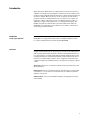
Notice
Please contact Agilent Technologies
for the latest information
or check the ESG Web site at
www.agilent.com/find/esg

2
Introduction . . . . . . . . . . . . . . . . . . . . . . . . . . . . . . . . . . . . . . . . . . . . . . . . . . . . . . . . . . . . . . . .3
Key Features . . . . . . . . . . . . . . . . . . . . . . . . . . . . . . . . . . . . . . . . . . . . . . . . . . . . . . . . . . . . . . .4
Specifications for Frequency and Power Characteristics . . . . . . . . . . . . . . . . . . . . . . . . . . .5
Frequency . . . . . . . . . . . . . . . . . . . . . . . . . . . . . . . . . . . . . . . . . . . . . . . . . . . . . . . . . . . . .5
Sweep modes . . . . . . . . . . . . . . . . . . . . . . . . . . . . . . . . . . . . . . . . . . . . . . . . . . . . . . . . . .5
Internal reference oscillator . . . . . . . . . . . . . . . . . . . . . . . . . . . . . . . . . . . . . . . . . . . . . .5
Output power . . . . . . . . . . . . . . . . . . . . . . . . . . . . . . . . . . . . . . . . . . . . . . . . . . . . . . . . . .6
Level accuracy . . . . . . . . . . . . . . . . . . . . . . . . . . . . . . . . . . . . . . . . . . . . . . . . . . . . .6
Repeatability and linearity . . . . . . . . . . . . . . . . . . . . . . . . . . . . . . . . . . . . . . . . . . .8
Spectral purity . . . . . . . . . . . . . . . . . . . . . . . . . . . . . . . . . . . . . . . . . . . . . . . . . . . . . . . .10
Specifications for Analog Modulation . . . . . . . . . . . . . . . . . . . . . . . . . . . . . . . . . . . . . . . . . .12
Frequency bands . . . . . . . . . . . . . . . . . . . . . . . . . . . . . . . . . . . . . . . . . . . . . . . . . . . . . .12
Frequency modulation . . . . . . . . . . . . . . . . . . . . . . . . . . . . . . . . . . . . . . . . . . . . . . . . . .12
Phase modulation . . . . . . . . . . . . . . . . . . . . . . . . . . . . . . . . . . . . . . . . . . . . . . . . . . . . . .13
Amplitude modulation . . . . . . . . . . . . . . . . . . . . . . . . . . . . . . . . . . . . . . . . . . . . . . . . . .13
Wideband AM . . . . . . . . . . . . . . . . . . . . . . . . . . . . . . . . . . . . . . . . . . . . . . . . . . . . . . . . .14
Pulse modulation . . . . . . . . . . . . . . . . . . . . . . . . . . . . . . . . . . . . . . . . . . . . . . . . . . . . . .14
Internal modulation source . . . . . . . . . . . . . . . . . . . . . . . . . . . . . . . . . . . . . . . . . . . . . .15
External modulation inputs . . . . . . . . . . . . . . . . . . . . . . . . . . . . . . . . . . . . . . . . . . . . . .15
External burst envelope . . . . . . . . . . . . . . . . . . . . . . . . . . . . . . . . . . . . . . . . . . . . . . . . .16
Composite modulation . . . . . . . . . . . . . . . . . . . . . . . . . . . . . . . . . . . . . . . . . . . . . . . . . .16
Simultaneous modulation . . . . . . . . . . . . . . . . . . . . . . . . . . . . . . . . . . . . . . . . . . . . . . .16
Specifications for I/Q Characteristics . . . . . . . . . . . . . . . . . . . . . . . . . . . . . . . . . . . . . . . . . .17
I/Q modulation bandwidth . . . . . . . . . . . . . . . . . . . . . . . . . . . . . . . . . . . . . . . . . . . . . .17
I/Q adjustments . . . . . . . . . . . . . . . . . . . . . . . . . . . . . . . . . . . . . . . . . . . . . . . . . . . . . . .18
Baseband generator [arbitrary waveform mode] . . . . . . . . . . . . . . . . . . . . . . . . . . . . .19
Baseband generator [real-time mode] . . . . . . . . . . . . . . . . . . . . . . . . . . . . . . . . . . . . .20
Specifications for Signal Personality Characteristics . . . . . . . . . . . . . . . . . . . . . . . . . . . . .21
3GPP W-CDMA . . . . . . . . . . . . . . . . . . . . . . . . . . . . . . . . . . . . . . . . . . . . . . . . . . . . . . . .21
IS-95 CDMA . . . . . . . . . . . . . . . . . . . . . . . . . . . . . . . . . . . . . . . . . . . . . . . . . . . . . . . . . .22
cdma2000 . . . . . . . . . . . . . . . . . . . . . . . . . . . . . . . . . . . . . . . . . . . . . . . . . . . . . . . . . . . .22
Enhanced multitone . . . . . . . . . . . . . . . . . . . . . . . . . . . . . . . . . . . . . . . . . . . . . . . . . . . .23
AWGN . . . . . . . . . . . . . . . . . . . . . . . . . . . . . . . . . . . . . . . . . . . . . . . . . . . . . . . . . . .23
802.11 WLAN . . . . . . . . . . . . . . . . . . . . . . . . . . . . . . . . . . . . . . . . . . . . . . . . . . . .24
Custom modulation . . . . . . . . . . . . . . . . . . . . . . . . . . . . . . . . . . . . . . . . . . . . . . .25
GSM/GPRS . . . . . . . . . . . . . . . . . . . . . . . . . . . . . . . . . . . . . . . . . . . . . . . . . . . . . .26
EDGE/EGPRS . . . . . . . . . . . . . . . . . . . . . . . . . . . . . . . . . . . . . . . . . . . . . . . . . . . .27
GSM/EDGE base station bit error rate test [BERT] . . . . . . . . . . . . . . . . . . . . . .28
Bit error rate [BER] analyzer . . . . . . . . . . . . . . . . . . . . . . . . . . . . . . . . . . . . . . . . . . . . .29
General Characteristics . . . . . . . . . . . . . . . . . . . . . . . . . . . . . . . . . . . . . . . . . . . . . . . . . . . . .30
Operating characteristics . . . . . . . . . . . . . . . . . . . . . . . . . . . . . . . . . . . . . . . . . . . . . . .30
Inputs and outputs . . . . . . . . . . . . . . . . . . . . . . . . . . . . . . . . . . . . . . . . . . . . . . . . . . . . .31
Ordering Information . . . . . . . . . . . . . . . . . . . . . . . . . . . . . . . . . . . . . . . . . . . . . . . . . . . . . . . .37
Related Literature . . . . . . . . . . . . . . . . . . . . . . . . . . . . . . . . . . . . . . . . . . . . . . . . . . . . . . . . . .38
Table of Contents

3
Agilent Technologies E4438C ESG vector signal generator incorporates a broad array of
capabilities for testing both analog and digital communications systems. Flexible options
provide test solutions that will evaluate the performance of nearly all current and proposed
air interface standards. Many test functions can be customized to meet the needs of
proprietary and other nonstandard wireless protocols as well. You can configure your
instrument to address a wide variety of tests—from altering nearly every aspect of a
digital signal or signal operating environment, to creating experimental signals. This
flexibility, along with an architecture that accepts future enhancements makes the
E4438C ESG vector signal generator an excellent choice for wireless communications
system testing now and in the future.
Choose your required frequency range as an Option when configuring your
E4438C ESG vector signal generator. Please refer to the E4438C Configuration Guide
for complete ordering information. Literature number 5988-4085EN.
Specifications (spec): Specifications describe the instrument’s warranted performance
and apply after a 45 minute warm-up. All specifications are valid over the signal generators
entire operating/environmental range unless otherwise noted. Supplemental character-
istics, denoted typical or nominal, provide additional [nonwarranted] information useful
in applying the instrument. Column headings labeled “standard” imply that this level of
performance is standard, without regard for option configuration. If a particular option
configuration modifies the standard performance, that performance is given in a separate
column.
Typical (typ): performance is not warranted. It applies at 25°C. 80% of all products meet
typical performance.
Nominal (nom): values are not warranted. They represent the value of a parameter that
is most likely to occur; the expected or mean value. They are included to facilitate the
application of the product.
Standard (std): No options are included when referring to the signal generator unless
noted otherwise.
Introduction
E4438C ESG
vector signal generator
Definitions

4
• Expandable architecture
• Broad frequency coverage
• Choice of electronic or mechanical attenuator
• Superior level accuracy
• Wideband FM and FM
• Step and list sweep, both frequency and power
• Built-in function generator
• Lightweight, rack-mountable
• 1-year standard warranty
• 2-year calibration cycle
• Broadband analog I/Q inputs
• I/Q adjustment capabilities and internal calibration routine
• Excellent modulation accuracy and stability
• Coherent carrier output up to 4 GHz
• Internal baseband generator, 8 or 64 MSa (40 or 320 MB) memory with
digital bus capability
• ESG digital input or output connectivity with N5102A Baseband Studio
digital signal interface module
• 6 GB internal hard drive
• Internal bit error rate (BER) analyzer
• High-stability time-base
• Enhanced phase noise performance
• High output power with mechanical attenuator
• Move all front panel connectors to the rear panel
• 3GPP W-CDMA FDD personality
• cdma2000 and IS-95-A personality
• TDMA personality (GSM, EDGE, GPRS, EGPRS, NADC, PDC, PHS, DECT, TETRA)
• Calibrated noise (AWGN) personality
• GPS personality
• Signal Studio for 1xEV-DO/1xEVDO Rev A
• Signal Studio for 1xEV-DV and cdma2000
• Signal Studio for 802.11 WLAN
• Signal Studio for Bluetooth™
• Signal Studio for enhanced multitone
• Signal Studio for HSDPA over W-CDMA
• Signal Studio for TD-SCDMA
• Signal Studio for Noise Power Ratio (NPR)
• Signal Studio for S-DMB
• Signal Studio for T-DMB
• Signal Studio for pulse building
• Signal Studio for jitter injection
• Signal Studio toolkit
• Signal Studio for 802.16-2004 (WiMAX)
• Signal Studio for 802.16 OFDMA
• Signal Studio for DVB
This document contains the measured specifications for the instrument platform
and personalities. It does not contain a full list of features for all optional
personalities. Please consult the individual product overviews for each
personality for a full listing of all features and capabilities. These are listed
at the end of this document.
Key Features
Key standard features
Optional features

5
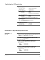
Frequency range
Option
1
501 250 kHz to 1 GHz
502 250 kHz to 2 GHz
503 250 kHz to 3 GHz
504 250 kHz to 4 GHz
506 250 kHz to 6 GHz [requires Option UNJ]
Frequency minimum 100 kHz
2
Frequency resolution 0.01 Hz
Frequency switching speed
3
Option 501-504 With Option UNJ Option 506
Freq.
4
Freq./Amp.
5
Freq.
4
Freq./Amp.
5
Freq.
4
Freq./Amp.
5
Digital modulation
on (< 35 ms) (< 49 ms) (< 35 ms) (< 52 ms) (< 41 ms) (< 57 ms)
off (< 9 ms) (< 9 ms) (< 9 ms (< 9 ms) (< 16 ms (< 17 ms)
[For hops < 5 MHz within a band]
Digital modulation
on (< 9 ms) (< 9 ms) (< 9 ms) (< 9 ms) (< 33 ms) (< 53 ms)
off (< 9 ms) (< 9 ms) (< 9 ms) (< 9 ms) (< 12 ms) (< 14 ms)
Phase offset Phase is adjustable remotely [LAN, GPIB, RS-232] or via front panel
in nominal 0.1° increments
Operating modes Frequency step, amplitude step and arbitrary list
Dwell time 1 ms to 60 s
Number of points 2 to 65,535
Stability
3
Standard With Option UNJ or 1E5
Aging rate < ±1 ppm/yr < ±0.1 ppm/yr or
< ±0.0005 ppm/day after 45 days
Temp [0 to 55° C] (< ±1 ppm) (< ±0.05 ppm)
Line voltage (< ±0.1 ppm) (< ±0.002 ppm)
Line voltage range (+5% to –10%) (+5% to –10%)
RF reference output
Frequency 10 MHz
Amplitude 4 dBm ±2 dB
RF reference input requirements
Standard With Option UNJ or 1E5
Frequency 1, 2, 5, 10 MHz ± 10 ppm 1, 2, 5, 10 MHz ±.2 ppm
Amplitude –3.5 dBm to 20 dBm
Input impedance 50 Ω
Specifications for Frequency and Power Characteristics
1. The E4438C is available as a vector platform only. For analog models refer to the E4428C.
2. Performance below 250 kHz not guaranteed.
3. Parentheses denote typical performance.
4. To within 0.1 ppm of final frequency above 250 MHz or within 100 Hz below 250 MHz.
5. Frequency switching time with the amplitude settled within ±0.1 dB.
Frequency
Sweep modes
Internal reference oscillator

6
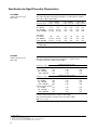
Power
Option 501-504 With Option UNB Option 506
250 kHz to 250 MHz +11 to –136 dBm +15 to –136 dBm +12 to –136 dBm
> 250 MHz to 1 GHz +13 to –136 dBm +17 to –136 dBm +14 to –136 dBm
> 1 to 3 GHz +10 to –136 dBm +16 to –136 dBm +13 to –136 dBm
> 3 to 4 GHz +7 to –136 dBm +13 to –136 dBm +10 to –136 dBm
> 4 to 6 GHz N/A N/A +10 to –136 dBm
Typical maximum available power
Level resolution 0.02 dB
Level range with Attenuator Hold active
Option 501-504 With Option UNB Option 506
250 kHz to 1 GHz 23 dB 27 dB 24 dB
> 1 to 3 GHz 20 dB 26 dB 23 dB
> 3 to 4 GHz 17 dB 23 dB 20 dB
> 4 to 6 GHz N/A N/A 20 dB
Level accuracy [dB]
Option 501-504
1,2
Power level
+7 to –50 to –110 to < –127 dBm
–50 dBm –110 dBm –127 dBm
250 kHz to 2.0 GHz ±0.5 ±0.5 ±0.7 (±1.5)
2.0 to 3 GHz ±0.6 ±0.6 ±0.8 (±2.5)
3 to 4 GHz ±0.7 ±0.7 ±0.9 (±2.5)
With Option UNB
2,3
Power level
+10 to –50 to –110 to < –127 dBm
–50 dBm –110 dBm –127 dBm
250 kHz to 2.0 GHz ±0.5 ±0.7 ±0.8 (±1.5)
2.0 to 3 GHz ±0.6 ±0.8 ±1.0 (±2.5)
3 to 4 GHz ±0.8 ±0.9 ±1.3 (±2.5)
Option 506
2, 4
Power level
+7 to –50 to –110 to < –127 dBm
–50 dBm –110 dBm –127 dBm
250 kHz to 2.0 GHz ±0.6 ±0.8 ±0.8 (±1.5)
2.0 to 3 GHz ±0.6 ±0.8 ±1.0 (±2.5)
3 to 4 GHz ±0.8 ±0.9 ±1.5 (±2.5)
4 to 6 GHz ±0.8 ±0.9 (±1.5)
Specifications for Frequency and Power Characteristics
1. Quoted specifications for 23 °C ± 5 °C. Accuracy
degrades by less than 0.03 dB/°C over full
temperature range. Accuracy degrades by 0.3 dB
above +7 dBm, and by 0.8 dB above +10 dBm.
2. Parentheses denote typical performance.
3. Quoted specifications for 23 °C ± 5 °C. Accuracy
degrades by less than 0.03 dB/°C over full
temperature range. Accuracy degrades by 0.2 dB
above +10 dBm, and by 0.8 dB above +13 dBm.
4. Quoted specifications for 23 °C ± 5 °C. Accuracy
degrades by less than 0.02 dB/°C over full
temperature range. Accuracy degrades by 0.2 dB
above +7 dBm.
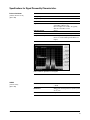
Power [dB]
3000
26
24
22
20
18
16
14
12
10
Frequency [MHz]
4000
Option 501-504
5000 60000 1000
2000
Option 506
Option UNB
Output power

7
Level accuracy with digital modulation turned on [relative to CW]
Conditions: [with PRBS modulated data;
if using I/Q inputs,
√ I
2
+ Q
2
= 0.5 V
rms
, nominal]
1
Level accuracy with ALC on
π/4 DQPSK or QPSK formats
Conditions: With raised cosine or root-raised cosine filter and a ≥ 0.35;
with 10 kHz ≤ symbol rate ≤ 1 MHz; at RF freq ≥ 25 MHz;
power ≤ max specified –3 dB
Option 501-504 Option 506
±0.15 dB ±0.25 dB
Constant amplitude formats [FSK, GMSK, etc]
Option 501-504 Option 506
±0.1 dB ±0.15 dB
Level accuracy with ALC off
1, 2
(±0.15 dB) [relative to ALC on]
Conditions: After power search is executed, with burst off.
Level switching speed
1
Option 501-504 With Option UNB Option 506
Normal operation [ALC on] (< 15 ms) (< 21 ms) (< 21 ms)
When using power search manual (< 83 ms) (< 95 ms) (< 95 ms)
When using power search auto (< 103 ms) (< 119 ms) (< 119 ms)
Specifications for Frequency and Power Characteristics
1. Parentheses denote typical performance.
2. When applying external I/Q signals with ALC off, output level will vary directly with I/Q input level.

8
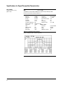
Repeatability and linearity
Relative level accuracy measures the accuracy of a step change from any power level to any
other power level. This is useful for large changes (i.e. 5 dB steps).
1
Specifications for Frequency and Power Characteristics
1. Repeatability and relative level accuracy are typical for all frequency ranges.
Repeatability
1900 MHz CW, 5 dBm, attenuator hold On, ALC On
0
20 40
60
80
100
120
Elapsed time (minutes)
Powererror (dB)
0.1
0.09
0.08
0.07
0.06
0.05
0.04
0.03
0.02
0.01
0
Typical unit
Limits
Repeatability
1900 MHz CW, 5 dBm, attenuator hold Off, ALC Off
0
1
Elapsed time (minutes)
Power error (dB)
0.5
0.45
0.4
0.35
0.3
0.25
0.2
0.15
0.10
0.05
0
2 3 54 6 71 8 910
Typical unit
Limits
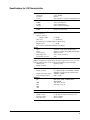
Relative level accuracy
Initial power 7 dBm
0
-20 -40 -60
Final power (dBm)
Power error (dB)
0.4
0.3
0.2
0.1
0
-0.1
-0.2
-0.3
-0.4
-140
-120-80 -100
Lower limit
Lower STD deviation
Mean
Upper STD deviation
Upper limit
Repeatability measures the ability of the instrument to return to a given power setting after a
random excursion to any other frequency and power setting. It is a relative measurement that
reflects the difference in dB between the maximum and minimum power readings for a given
setting over a specific time interval. It should not be confused with absolute power accuracy,
which is measured in dBm.
1

1. Repeatability and relative level accuracy are typical for all frequency ranges.
9
Linearity
CW or GSM, 1900 MHz, attenuator hold On, ALC On
-10
-8 -6 -4 -2
0
812
Amplitude (dBm)
ALC offset error (dB)
0.3
0.25
0.2
0.15
0.1
0.05
0
-0.05
-0.1
-0.15
-0.2
-0.25
-0.3
14 16
10
2
46
Typical STD unit
Typical Option 506 unit
Typical Option UNB unit
Lower limit
Upper limit
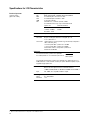
Linearity
W-CDMA 2200 MHz, attenuator hold On, ALC On
-10
-8 -6
-4 -2 0 2 4
Amplitude (dBm)
ALC offset error (dB)
0.3
0.25
0.2
0.15
0.1
0.05
0
-0.05
-0.1
-0.15
-0.2
-0.25
-0.3
68
Typical STD unit
Typical Option UNB unit
Typical Option 506 unit
Lower limit
Upper limit
Linearity
CW or GSM 5750 MHz, attenuator hold On, ALC On
-10
-8
Amplitude (dBm)
ALC offset error (dB)
0.3
0.25
0.2
0.15
0.1
0.05
0
-0.05
-0.1
-0.15
-0.2
-0.25
-0.3
-6 -4 -2 0 2 4 6 8 10
Typical STD unit
Lower STD deviation
Upper STD deviation
Lower limit
Upper limit
Linearity
W-CDMA 5750 MHz, attenuator hold On, ALC On
-10
-8
-6
-4 -2 0
2
468
Amplitude (dBm)
ALC Offset error (dB)
0.3
0.25
0.2
0.15
0.1
0.05
0
-0.05
-0.1
-0.15
-0.2
-0.25
-0.3
Mean,Option 506 unit
Lower STD deviation
Upper STD deviation
Lower limit
Upper limit
Linearity measures the accuracy of small changes while the attenuator
is held in a steady state (to avoid power glitches). This is useful for fine
resolution changes.
1
Specifications for Frequency and Power Characteristics
Linearity
CW or GSM, 850 MHz, attenuator hold On, ALC On
-10
-8 -6 -4 -2 0 8
12
Amplitude (dBm)
ALC offset error (dB)
0.3
0.25
0.2
0.15
0.1
0.05
0
-0.05
-0.1
-0.15
-0.2
-0.25
-0.3
-0.35
-0.4
141024 6
Typical STD unit
Typical Option UNB unit
Typical Option 506 unit
Lower limit
Upper limit
16
Limit is undefined above 13 dBM
for STD units. Limit line applies
only to UNB and 506 units.

10
SSB Phase noise [at 20 kHz offset]
1
Standard With Option UNJ
at 500 MHz (< –124 dBc/Hz) < –135 dBc/Hz, (< –138 dBc/Hz)
at 1 GHz (< –118 dBc/Hz) < –130 dBc/Hz, (< –134 dBc/Hz)
at 2 GHz (< –112 dBc/Hz) < –124 dBc/Hz, (< –128 dBc/Hz)
at 3 GHz (< –106 dBc/Hz) < –121 dBc/Hz, (< –125 dBc/Hz)
at 4 GHz (< –106 dBc/Hz) < –118 dBc/Hz, (< –122 dBc/Hz)
at 6 GHz N/A < –113 dBc/Hz, (< –117 dBc/Hz)
Residual FM
1
[CW mode, 0.3 to 3 kHz BW, CCITT, rms]
Option UNJ < N x 1 Hz (< N x 0.5 Hz)
2
Standard
Phase noise mode 1 < N x 2 Hz
Phase noise mode 2 < N x 4 Hz
Harmonics
1, 3
[output level ≤ +4 dBm, ≤ +7.5 dBm Option UNB, ≤ +4.5 dBm Option 506]
< –30 dBc above 1 GHz, (< –30 dBc 1 GHz and below)
Nonharmonics
1, 4
[≤ +7 dBm output level, ≤ +4 dBm Option 506]
Standard
5
With Option UNJ
6
> 3 kHz > 10 kHz
> 3 kHz
> 10kHz
offset offset
< 10 kHz
offset
offset
250 kHz to 250 MHz < –53 dBc (< –68 dBc) (< –58 dBc) < –65 dBc (< –58 dBc)
250 MHz to 500 MHz < –59 dBc (< –74 dBc) (< –81 dBc) < –80 dBc < –80 dBc
500 MHz to 1 GHz < –53 dBc (< –68 dBc) (< –75 dBc) < –80 dBc < –80 dBc
1 to 2 GHz < –47 dBc (< –62 dBc) (< –69 dBc) < –74 dBc < –74 dBc
2 to 4 GHz < –41 dBc (< –56 dBc) (< –63 dBc) < –68 dBc < –68 dBc
4 to 6 GHz N/A N/A N/A < –62 dBc < –62 dBc
Subharmonics
Standard With Option UNJ
≤ 1 GHz None None
>1 GHz < –40 dBc None
Jitter in µUI
1, 7, 8
Carrier SONET/SDH rms jitter Standard With option UNJ
frequency data rates bandwidth (µUI rms) (µUI rms)
155 MHz 155 MB/s 100 Hz to 1.5 MHz (359) (78)
622 MHz 622 MB/s 1 kHz to 5 MHz (158) (46)
2.488 GHz 2488 MB/s 5 kHz to 15 MHz (384) (74)
Jitter in seconds
1, 7, 8
Carrier SONET/SDH rms jitter
Standard With option UNJ
frequency data rates bandwidth
155 MHz 155 MB/s 100 Hz to 1.5 MHz (2.4 ps) (0.6 ps)
622 MHz 622 MB/s 1 kHz to 5 MHz (255 fs) (74 fs)
2.488 GHz 2488 MB/s 5 kHz to 15 MHz (155 fs) (30 fs)
Specifications for Frequency and Power Characteristics
1. Parentheses denote typical performance.
2. Refer to frequency bands on page 12 for N values.
3. Harmonic performance outside the operating range of the instrument is typical.
4. Spurs outside the operating range of the instrument are not specified.
5. Specifications apply for FM deviations < 100 kHz and are not valid on FM. For non-constant amplitude formats, unspecified spur levels occur up to the
second harmonic of the baseband rate.
6. Specifications apply for CW mode only.
7. Calculated from phase noise performance in CW mode only at -2.5 dBm for standard instruments, -0.5 dBm with Option 506, and +2.5 dBm with Option UNB.
8. For other frequencies, data rates, or bandwidths, please contact your sales representative.
Spectral purity

11
Characteristic SSB phase noise
With Option 1E5 With Option UNJ
fc = 850 MHz fc = 850 MHz
fc = 1900 MHz fc = 1900 MHz
fc = 2200 MHz fc = 2200 MHz
Phase noise modes 1 and 2 at fc = 900 MHz fc = 5.7 GHz [Option 506]
Specifications for Frequency and Power Characteristics
I/Q on
CW mode
CW mode
CW mode
PN mode 1
PN mode 2
CW mode
CW mode
CW mode
I/Q on or CW mode
I/Q on
I/Q on
I/Q on
I/Q on
I/Q on

12
Band Frequency range N number
1 250 kHz to ≤ 250 MHz 1
2 > 250 MHz to ≤ 500 MHz 0.5
3 > 500 MHz to ≤ 1GHz 1
4 > 1 to ≤ 2 GHz 2
5 > 2 to ≤ 4 GHz 4
6 > 4 to ≤ 6 GHz 8
Maximum deviation
3
Standard With Option UNJ
N x 8 MHz N x 1 MHz
Resolution 0.1% of deviation or 1 Hz,
whichever is greater
Modulation frequency rate
4
[deviation = 100 kHz]
Coupling 1 dB bandwidth 3 dB bandwidth
FM path 1[DC] DC to 100 kHz (DC to 10 MHz)
FM path 2 [DC] DC to 100 kHz (DC to 0.9 MHz)
FM path 1 [AC] 20 Hz to 100 kHz (5 Hz to 10 MHz)
FM path 2 [AC] 20 Hz to 100 kHz (5 Hz to 0.9 MHz)
Deviation accuracy
3
[1 kHz rate, deviation < N x 100 kHz]
< ± 3.5% of FM deviation + 20 Hz
Carrier frequency accuracy relative to CW in DCFM
3, 5
±0.1% of set deviation + (N x 1 Hz)
Distortion
3
[1 kHz rate, dev.= N x 100 kHz]
< 1%
FM using external inputs 1 or 2
Sensitivity 1 V
peak
for indicated deviation
Input impedance 50 Ω, nominal
FM path 1 and FM path 2 are summed internally for composite modulation.
The FM 2 path is limited to a maximum rate of 1 MHz. The FM 2 path must be
set to a deviation less than FM 1 path.
Specifications for Analog Modulation
1. All analog performance above 4 GHz is typical.
2. For non-Option UNJ units, specifications apply in phase noise mode 2 [default].
3. Refer to frequency bands on this page to compute specifications.
4. Parentheses denote typical performance.
5. At the calibrated deviation and carrier frequency, within 5 °C of ambient temperature at time of calibration.
Frequency bands
Frequency modulation
1,2

13
Resolution 0.1% of set deviation
Modulation frequency response
3, 4
Standard
Maximum Allowable rates [3 dB BW]
Mode deviation FM path 1 FM path 2
Normal BW N x 80 rad DC to 100 kHz DC to 100 kHz
High BW
6
N x 8 rad (DC to 1 MHz) (DC to 0.9 MHz)
N x 1.6 rad (DC to 10 MHz) (DC to 0.9 MHz)
With Option UNJ
Maximum Allowable rates [3 dB BW]
Mode deviation FM path 1 FM path 2
Normal BW N x 10 radians DC to 100 kHz DC to 100 kHz
High BW N x 1 radians (DC to 1 MHz) (DC to 0.9 MHz)
Deviation accuracy [1 kHz rate, Normal BW mode]
< ±5% of deviation + 0.01 radians
Distortion
3
[1 kHz rate, deviation < 80 radians on standard model, < 10 N radians on
Option UNJ models, Normal BW mode]
< 1%
FM using external inputs 1 or 2
Sensitivity 1 V
peak
for indicated deviation
Input impedance 50 Ω, nominal
Paths FM path 1 and FM path 2 are summed internally for composite
modulation. The FM 2 path is limited to a maximum rate of
1 MHz. FM path 2 must be set to a deviation less than the FM
path 1.
Range 0 to 100%
Resolution 0.1%
Rates [3 dB bandwidth]
DC coupled 0 to 10 kHz
AC coupled 10 Hz to 10 kHz
Accuracy
4, 7
1 kHz rate < ±(6% of setting +1%)
Distortion
4, 7
[1 kHz rate, THD]
Option 501-504/Option UNJ Option 506
30% AM < 1.5% < 1.5%
90% AM (< 4%) (< 5%)
AM using external inputs 1 or 2
Sensitivity 1 V
peak
to achieve indicated depth
Input impedance 50 Ω, nominal
Paths AM path 1 and AM path 2 are summed internally for
composite modulation.
Specifications for Analog Modulations
1. All analog performance above 4 GHz is typical.
2. For non-Option UNJ units, specifications apply in phase noise mode 2 [default].
3. Refer to frequency bands on page 12 for N.
4. Parentheses denote typical performance.
5. Bandwidth is automatically selected based on deviation.
6. AM is typical above 3 GHz or if wideband AM or I/Q modulation is simultaneously enabled.
7. Peak envelope power of AM must be 3 dB less than maximum output power below 250 MHz.
Phase modulation
1, 2
Amplitude modulation
1, 6
[fc > 500 kHz]

14
Rates [1 dB bandwidth]
1
ALC on (400 Hz to 40 MHz)
ALC off (DC to 40 MHz)
Wideband AM using external I input only
Sensitivity 0.5 V = 100%
Input impedance 50 Ω, nominal
On/off ratio
1
≤ 4 GHz > 80 dB
> 4 GHz (> 64 dB)
Rise/fall times
1
(150 ns)
Minimum width
1
ALC on (2 µs)
ALC off (0.4 µs)
Pulse repetition frequency
1
ALC on (10 Hz to 250 kHz)
ALC off (DC to 1.0 MHz)
Level accuracy
1, 2
[relative to CW at ≤ 4 dBm standard, ≤ 7.5 dBm Option UNB,
≤ 4.5 dBm Option 506]
(< ±1 dB)
Pulse modulation using external inputs
Input voltage
RF on > +0.5 V, nominal
RF off < +0.5 V, nominal
Input impedance 50 Ω, nominal
Internal pulse generator
Square wave rate 0.1 Hz to 20 kHz
Pulse
Period 8 µs to 30 seconds
Width 4 µs to 30 seconds
Resolution 2 µs
Specifications for Analog Modulation
1. Parentheses denote typical performance.
2. With ALC off, specifications apply after the execution of power search. With ALC on, specifications apply for pulse repetition rates ≤ 10 kHz and pulse widths ≥ 5 µs.
Wideband AM
Pulse modulation

Specifications for Analog Modulation
Waveforms Sine, square, ramp, triangle, pulse, noise
Rate range
Sine 0.1 Hz to 100 kHz
Square, ramp, triangle 0.1 Hz to 20 kHz
Resolution 0.1 Hz
Frequency accuracy Same as RF reference source
Swept sine mode [frequency, phase continuous]
Operating modes Triggered or continuous sweeps
Frequency range 0.1 Hz to 100 kHz
Sweep time 1 ms to 65 sec
Resolution 1 ms
Dual sinewave mode
Frequency range 0.1 Hz to 100 kHz
Amplitude ratio 0 to 100%
Amplitude ratio resolution 0.1%
LF audio out mode
Amplitude 0 to 2.5 V
peak
into 50 Ω
Output impedance 50 Ω nominal
Modulation types
Ext 1 FM, FM, AM, pulse, and burst envelope
Ext 2 FM, FM, AM, and pulse
LO/HI annunciator [100 Hz to 10 MHz BW, AC coupled inputs only]. Activated when
input level error exceeds 3% [nominal].
Internal modulation source
Provides modulating signal for FM, AM,
pulse and phase modulation signals, and
provides LF output source for basic function
generator capability.
External modulation inputs
15

16
Input voltage
RF On 0 V
RF Off –1.0 V
Linear control range 0 to –1 V
On/off ratio
1
Condition: V
in
below –1.05 V
≤ 4 GHz > 75 dB
> 4 GHz (> 64 dB)
Rise/fall time
1
Condition: With rectangular input
(< 2 µs)
Minimum burst repetition frequency
1
ALC on (10 Hz)
ALC off DC
Input port External 1
Input impedance 50 Ω, nominal
AM, FM, and FM each consist of two modulation paths which are summed internally for
composite modulation. The modulation sources may be any two of the following: Internal,
External 1, External 2.
Multiple modulation types may be simultaneously enabled. For example, W-CDMA, AM,
and FM can run concurrently and all will affect the output RF. This is useful for simulating
signal impairments. There are some exceptions: FM and FM cannot be combined; AM
and Burst envelope cannot be combined; Wideband AM and internal I/Q cannot be
combined. Two modulation types cannot be generated simultaneously by the same
modulation source.
Specifications for Analog Modulation
External burst envelope
Composite modulation
Simultaneous modulation
1. Parentheses denote typical performance.

17
I/Q inputs
Input impedance 50 Ω or 600 Ω
Full scale input
1
√ I
2
+ Q
2
= 0.5 V
rms
I/Q bandwidth using external I/Q source (ALC off)
2
I/Q bandwidth using internal I/Q source (Options 001, 002, 601, 602)
Specifications for I/Q Characteristics
1. The optimum I/Q input level is √ I
2
+Q
2
= 0.5 V
rms
, I/Q drive level affects EVM, origin offset, spectral regrowth, and noise floor. Typically, level accuracy
with ALC on will be maintained with drive levels between 0.25 and 1.0 V
rms
.
2. Parentheses denote typical performance.
[dB]
-100 0-50
Frequency offset from carrier [MHz]
50-150 150100
3.00
1.00
-1.00
-3.00
-5.00
-7.00
-9.00
-11.00
-13.00
-15.00
1800 MHz carrier
850 MHz carrier
1900 MHz carrier
2200 MHz carrier
3.00
1.00
-1.00
-3.00
-5.00
-7.00
-9.00
-11.00
-13.00
-15.00
Frequency offset from carrier [MHz]
-50
-30 -10 10
30 50
850 MHz
1800 MHz
1900 MHz
2200 MHz
5700 MHz
[dB]
I/Q modulation bandwidth

18
Source Parameter Range
I/Q baseband inputs Impedance 50 or 600 Ω
I offset [600 Ω only] ± 5 V
Q offset [600 Ω only] ± 5 V
I/Q baseband outputs I/Q offset adjustment ± 3 V
I/Q offset resolution 1 mV
I/Q gain balance ± 4 dB
I/Q attenuation 0 to 40 dB
I/Q low pass filter 40 MHz, through
RF output I/Q offset adjustment ± 50%
I/Q gain balance ± 4 dB
I/Q attenuation 0 to 40 dB
I/Q quad skew
[≤ 3.3 GHz] ± 10°
[> 3.3 GHz] ± 5°
I/Q low pass filter 2.1 MHz, 40 MHz, through
I/Q baseband outputs
1
Differential outputs I, I, Q, Q
Single ended I, Q
Frequency range DC to 40 MHz [with sinewave]
Output voltage into 50 Ω (1.5 V P-P) [with sinewave]
Output impedance 50 Ω nominal
Specifications for I/Q Characteristics
I/Q adjustments
Channels 2 [I and Q]
Resolution 16 bits [1/65,536]
Arbitrary waveform memory
Maximum playback capacity 8 megasamples (MSa)/channel [Option 601]
64 MSa/channel [Option 602]
Maximum storage capacity 1.2 GSa [Option 005]
2.8 MSa [Standard]
Waveform segments
Segment length 60 samples to 8 or 64 MSa
Maximum number of segments 1,024 [8 MSa volatile memory]
8,192 [64 MSa volatile memory]
Minimum memory allocation 256 samples or 1 KB blocks
Waveform sequences
Maximum total number of segment files
stored in the non-volatile
file system 16,384
Sequencing Continuously repeating
Maximum number of sequences 16,384 [shared with number of segments]
Maximum segments/sequence 32,768 [including nested segments]
Maximum segment repetitions 65,536
Baseband generator
[arbitrary waveform mode]
[Option 601 or 602]
1. Parentheses denote typical performance.

19
Clock
Sample rate 1 Hz to 100 MHz
Resolution 0.001 Hz
Accuracy Same as timebase +2
-42
[in non-integer applications]
Baseband filters
40 MHz used for spur reduction
2.1 MHz used for ACPR reduction
Through used for maximum bandwidth
Reconstruction filter: [fixed]
50 MHz [used for all symbol rates]
Baseband spectral purity
1
[full scale sinewave]
Harmonic distortion
100 kHz to 2 MHz (< –65 dBc)
Phase noise (< –127 dBc/Hz)
[baseband output of 10 MHz sinewave at 20 kHz offset]
IM performance (< –74 dB)
[two sinewaves at 950 kHz and 1050 kHz at baseband]
Triggers
Types Continuous, single, gated, segment advance
Source Trigger key, external, remote [LAN, GPIB, RS-232]
External polarity Negative, positive
External delay time 10 ns to 40 sec plus latency
External delay resolution 10 ns
Markers
[Markers are defined in a segment during the waveform generation process, or from the
ESG front panel. A marker can also be tied to the RF blanking feature of the ESG.]
Marker polarity Negative, positive
Number of markers 4
Multicarrier
Number of carriers Up to 100 [limited by a max bandwidth of 80 MHz
depending on symbol rate and modulation type]
Frequency offset [per carrier] –40 MHz to +40 MHz
Power offset [per carrier] 0 dB to –40 dB
Modulation
PSK BPSK, QPSK, OQPSK, π/4DQPSK, 8PSK,
16PSK, D8PSK
QAM 4, 16, 32, 64, 128, 256
FSK Selectable: 2, 4, 8, 16
MSK
ASK
Data Random ONLY
Multitone
Number of tones 2 to 64, with selectable on/off state per tone
Frequency spacing 100 Hz to 80 MHz
Phase [per tone] Fixed or random
Specifications for I/Q Characteristics
1. Parentheses denote typical performance.

20
Basic modulation types [custom format]
PSK BPSK, QPSK, OQPSK, π/4DQPSK, 8PSK, 16PSK, D8PSK
MSK User-defined phase offset from 0 to 100°
ASK User-defined depth from 0.001 to 100%
QAM 4, 16, 32, 64, 128, 256
FSK Selectable: 2, 4, 8, 16 level symmetric, C4FM
User defined: Custom map of up to 16 deviation levels
Symbol rate Maximum deviation
< 5 MHz 4 times symbol rate
> 5 MHz, < 50 MHz 20 MHz
Resolution: 0.1 Hz
I/Q Custom map of 256 unique values
FIR filter
Selectable Nyquist, root Nyquist, Gaussian, rectangular, Apco 25
a: 0 to 1, B
b
T: 0.1 to 1
Custom FIR 16-bit resolution, up to 64 symbols long, automatically resampled to
1024 coefficients [max]
> 32 to 64 symbol filter: symbol rate ≤ 12.5 MHz
> 16 to 32 symbol filter: symbol rate ≤ 25 MHz
Internal filters switch to 16 tap when symbol rate is
between 25 and 50 MHz
Symbol rate
For external serial data, symbol rate is adjustable
from 1000 symbols/sec to a maximum symbol rate of
50 Mbits/sec
#bits/symbol
For internally generated data, symbol rate is adjustable from 1000 symbols/sec to
50 Msymbols/sec. and a maximum of 8 bits per symbol. Modulation quality may be
degraded at high symbol rates.
Baseband reference frequency
Data clock can be phase locked to an external reference.
13 MHz for GSM, 250 kHz to 100 MHz in W-CDMA and cdma2000
1, 2
Input ECL, CMOS, TTL compatible, 50 Ω AC coupled
Frame trigger delay control
Range 0 to 1,048,575 bits
Resolution 1 bit
Specifications for I/Q Characteristics
1. Performance below 1 MHz not specified.
2. When used, this baseband reference is independent of the 10 MHz RF reference.
Baseband generator
[real-time mode]
[Option 601 or 602]
Page is loading ...
Page is loading ...
Page is loading ...
Page is loading ...
Page is loading ...
Page is loading ...
Page is loading ...
Page is loading ...
Page is loading ...
Page is loading ...
Page is loading ...
Page is loading ...
Page is loading ...
Page is loading ...
Page is loading ...
Page is loading ...
Page is loading ...
Page is loading ...
Page is loading ...
Page is loading ...
-
 1
1
-
 2
2
-
 3
3
-
 4
4
-
 5
5
-
 6
6
-
 7
7
-
 8
8
-
 9
9
-
 10
10
-
 11
11
-
 12
12
-
 13
13
-
 14
14
-
 15
15
-
 16
16
-
 17
17
-
 18
18
-
 19
19
-
 20
20
-
 21
21
-
 22
22
-
 23
23
-
 24
24
-
 25
25
-
 26
26
-
 27
27
-
 28
28
-
 29
29
-
 30
30
-
 31
31
-
 32
32
-
 33
33
-
 34
34
-
 35
35
-
 36
36
-
 37
37
-
 38
38
-
 39
39
-
 40
40


Agilent Technologies E4438C User manual
- Category
- Supplementary music equipment
- Type
- User manual
Ask a question and I''ll find the answer in the document
Finding information in a document is now easier with AI
Related papers
-
Agilent Technologies E4406A User manual
-
-
-
-
-
-
-
-
-
Other documents
-
 EnGenius Technologies ESG-8808R User manual
-
Keysight N4906B Serial BERT Quick start guide
-
 MFJ 806 User manual
-
Anritsu MG3690A User manual
-
MGC ALC-480 Dual Loop Adder User manual
-
Aeroflex 2023A Operating instructions
-
Tektronix AWGSYNC01 Technical Reference
-
Cirago HS-450SIL Datasheet
-
-

