
BEFORE YOU BEGIN
Read these instructions completely
and carefully.
IMPORTANT – Save these instruc-
tions for local inspector’s use.
IMPORTANT – Observe all governing
codes and ordinances.
Note to Installer – Be sure to leave these
instructions with the Consumer.
Note to Consumer – Keep these instructions
with your Owner’s Manual for future
reference.
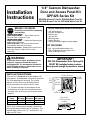
Installation
Instructions
1/4" Custom Dishwasher
Door and Access Panel Kit
GPF425 Series Kit
GPF425A-Almond Trim Kit, GPF425B-Black Trim Kit,
GPF425C-Bisque Trim Kit, GPF425W-White Trim Kit
WARNING:
To prevent electric shock, disconnect electri-
cal power supply to dishwasher before
changing panels. Do not operate dishwasher
while changing panels or when lower access
panel assembly is removed.
TOOLS AND MATERIALS REQUIRED:
• 1/4" socket driver
• Phillips screwdriver
• Electric drill
• 1/8" drill bit
• Masking tape
• Safety glasses
• Gloves to protect against sharp edges
KIT INCLUDES:
• Left, right and bottom door trim
• Top and bottom access panel trim
• Color matched screws
STOP
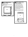
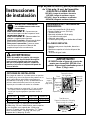
INSTALLATION OPTIONS
This trim kit is designed to accommodate 1/4"
thick panels. A raised panel screwed or glued to
1/4" thick backing can be used. The raised
portion of the panel must be fabricated to
permit clearances for the trim on all sides.
• “X” Clearance shown at the bottom of the
raised panel must be maintained to prevent
the door from striking the access panel when
opened.
Appearance Total “X”
Panel Backing Thickness Clearance
3/4" 1/4" 1" 2"
1/2" 1/4" 3/4" 1-7/8"
A 3/4" thick custom panel may be installed by
routing the top and sides to 1/4" thickness. The
bottom edge, Dimension “X”, should be 1-1/2"
high and 1/4" thick.
IMPORTANT!
GPF100 Dishwasher Door Spring Kit
MUST BE installed when custom
door panels weigh 4 pounds or more.
18-7/8"
1/4" Min. Clearance
23-9/16"
Appearance
Panel
1/4"
Thick
Panel
1/8" Min.
Clearance
1/8" Min.
Clearance
X
Clearance
3-11/16"
1/4" Min. Clearance
All Sides
29-9/16"
Access Panel

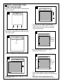
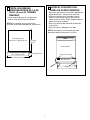
2 REMOVE LOWER ACCESS
PANEL ASSEMBLY
• Remove the two screws below the
access panel. Retain screws.
• Loosen the two screws located
between the door and the access
panel. Do not attempt to remove
these screws. They are secured to
the access panel with washers.
• Remove the access panel assembly
from the dishwasher.
• Remove the toekick and set aside.
NOTE: Do not remove the insulation
behind the access panel or toekick.
1 CUT 1/4" THICK CUSTOM
PANELS TO SIZE
• Cut door panel and access panel to the
dimensions shown.
NOTE: The trim provided will conceal the cut
edges of the panels.
2
1/4" Thick
Door Panel
23-9/16"
3-11/16"
19-3/4"
1/4" Thick Access Panel
Loosen 2 Screws
Escutcheon
Door
Panel
Access Panel
Toekick
Loosen 2 Screws
Escutcheon
Door
Panel
Access Panel
Toekick

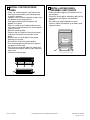
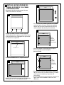
3 INSTALL DOOR PANEL TRIM
AND CUSTOM PANEL
• Remove the protective plastic covering from
side trim pieces.
• Slide “Z” shaped trim under the escutcheon.
• Place bottom trim against the bottom of the
door panel and drive center screw, then left
and right screws.
• Slide custom door panel under the “Z” trim
and bottom trim.
• The notch on the side trim pieces goes
towards the front. Slide side trim up and
under the escutcheon and over the edge
of the custom panel.
• Center punch and drill holes through the
holes in the side trim and into the dishwasher
door.
• Secure the trim to the door with color
matched screws provided. Remove tape.
• Use masking tape to hold trim tightly
against the custom panel.
A
B
C
D
F
E
3
“Z” Trim
Tape Trim
to Custom
Panel on
Each Side
Drill Holes
and Install
Screws

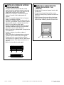
5 INSTALL ACCESS PANEL
ASSEMBLY AND TOEKICK
• Place the toekick against the bottom of the
dishwasher.
• Place the access panel assembly against the
dishwasher and tighten the attached
screws.
• Re-install two original bottom screws
loosely. Adjust the toekick up or down and
tighten screws.
4 INSTALL CUSTOM ACCESS
PANEL
• Place 1/4" custom panel in position on the
access panel assembly. Use masking tape
to hold in position.
• Loosely, install 3 color matched screws into
the bottom of the access panel.
• Peel paper backing off the tape on the
bottom trim piece.
• Slip trim under screw heads and press the
trim against the bottom of the access panel.
Tighten screws.
• Remove masking tape.
• Position top trim against the custom panel
and form the ends over the sides of the
panel.
• Remove the trim and peel off the paper
backing on the tape.
• Reinstall the trim over the assembly.
• Use masking tape to hold the trim against
the panel on each side.
• Drill holes through the side trim holes and
into the access panel. Secure each side with
one screw.
• Remove masking tape.
Pub. No. 31-30500-2 SPECIFICATIONS SUBJECT TO CHANGE WITHOUT NOTICE DWG. NO. 206C1559P036
(ND 923-16) 2/04
Tighten
2 Screws
Page is loading ...
Page is loading ...
Page is loading ...

5 INSTALE EL CONJUNTO DEL
PANEL DE ACCESO Y LA
REJILLA
• Ponga la rejilla contra la parte inferior del
lavavajillas.
• Ponga el conjunto del panel de acceso
contra el lavavajillas y apriete los tornillos
adjuntos.
• Vuelva a atornillar los tornillos inferiores
originales, sin apretarlos. Ajuste la rejilla
hacia arriba o abajo y apriete los tornillos.
4 INSTALE EL PANEL DE ACCESO
PERSONALIZADO
• Ponga el panel personalizado de 1/4 de
pulg. (6 mm) en posición sobre el conjunto
del panel de acceso. Use cinta adhesiva de
papel para mantenerlo en posición.
• Atornille, sin apretar, 3 tornillos de igual
color en la parte inferior del panel de
acceso.
• Retire el respaldo de papel de la cinta que
está en la moldura inferior.
• Coloque la moldura bajo las cabezas de los
tornillos y presiónela contra la parte inferior
del panel de acceso. Apriete los tornillos.
• Retire la cinta adhesiva de papel.
• Ponga la moldura superior contra el panel
personalizado de forma que los extremos
coincidan con los lados del panel.
• Retire la moldura y desprenda el papel de la
cinta adhesiva.
• Vuelva a colocar la moldura sobre el
conjunto.
• Use cinta adhesiva de papel para sujetar la
moldura contra cada extremo del panel.
• Taladre orificios a través de los orificios
existentes en la moldura lateral y dentro del
panel de acceso. Fije cada extremo con un
tornillo.
• Retire la cinta adhesiva de papel.
Pub. No. 31-30500-2 ESPECIFICACIONES SUJETAS A CAMBIO SIN PREVIO AVISO DWG. NO. 206C1559P036
(ND 923-16) 2/04
Apriete los
2 tornillos
-
 1
1
-
 2
2
-
 3
3
-
 4
4
-
 5
5
-
 6
6
-
 7
7
-
 8
8


GE Profile GPF425B Installation guide
- Type
- Installation guide
Ask a question and I''ll find the answer in the document
Finding information in a document is now easier with AI
in other languages
Related papers
Other documents
-
GE GPF325W Installation guide
-
-
-
-
-
-
-
-
-
KitchenAid 2209478 User manual