Page is loading ...

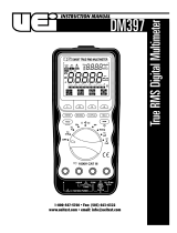
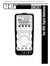
1-800-547-5740 • Fax: (503) 643-6322
www.ueitest.com • email: [email protected]
DM420
INSTRUCTION MANUAL

• Read the safety precautions associated with the equipment being
tested and seek assistance or advice when performing
unfamiliar tasks.
• Keep your fingers away from the test lead metal probe contacts
and bus-bars when making measurements. Always grip the
instrument and test-leads behind the hand guards (molded into
the probes).
• In the event of electrical shock, ALWAYS bring the victim to
the emergency room for evaluation, regardless of the victim’s
apparent recovery. Electrical shock can cause an unstable heart
rhythm that may need medical attention.
International Symbols
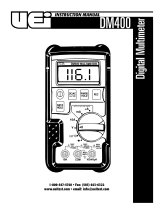
C o n t r ols and Indicators
1. “A” Input Jack: The red test lead is plugged into this jack for
measuring current on the 2 and 10 AC or DC amp functions.
2. “mAµA” ( ) Input Jack: The red test lead is plugged into
this jack for measuring mA or µA on either AC or DC current functions.
3. “COM” Input Jack: The black test lead is plugged into this jack
for all measurements.
4. “VΩ” ( ) Input Jack: The red test lead is plugged into this
jack for all AC volts, DC volts, OHM, Continuity Buzzer and Diode
test functions.
5. “ON/OFF” Push-button: Turns the meter on and off.
6. “Hold” Push-button: Freezes the reading on the LCD for all
functions and ranges.
Introduction
The DM420 combines the best features of the DM383 and DM410 with a
wide capacitance range. This new feature allows measurement of run and
start ca p a c i t o r s .
Features include
• 3-3/4 digit LCD display with 0.91” tall numerals
• Data Hold
• Diode Test
• Rubber boot
• 600 Volt fuse protection on all current ranges
• Continuity buzzer
• Auto polarity
• Capacitance up to 20,000 µF
Safety Notes
Before using this meter, read all safety information carefully. In
this manual the word "WARNING" is used to indicate conditions
or actions that may pose physical hazards to the user. The word
"CAUTION" is used to indicate conditions or actions that may
damage this instrument.
WARNING!
Exceeding the specified limits of this meter is dangerous and can
expose the user to serious or possibly fatal injury.
• DO NOT attempt to measure any voltage that exceeds 1000 V DC
or 750 V AC peak
• Voltages above 25 volts DC or 25 volts AC may constitute a
serious shock hazard
• DO NOT attempt to use this meter if either the meter or the test
leads have been damaged. Send unit in for repair by a qualified
repair facility
• Test leads must be fully inserted prior to taking measurements
• Always turn off power to a circuit (or assembly) under test before
cutting, unsoldering or breaking the current path. Even small
amounts of current can be dangerous
• Always disconnect the live test lead before disconnecting the
common test lead from a circuit
• When measuring high voltage, disconnect the power source before
making test lead connections. Connect the test leads to the meter
first then to the circuit under test. Reapply power
• If any of the following indications occur during testing, turn
off the power source to the circuit under test:
• Arcing
• Flame
• Smoke
• Extreme Heat
• Smell of Burning Materials
• Discoloration or Melting of Components
DM420-MAN P. 1
1

5. Reapply power to the circuit. The measured voltage will appear on
the display of the instrument.
6. Disconnect the power to the circuit before removing the test leads
from the circuit.
Maximum Input Voltage - 750 Peak AC V
Frequency Response - 50 Hz to 400 Hz
Input Impedance - 20 MΩ
Measuring DC Current (Amps)
CAUTION!
The current functions are protected by a fuse of 600 volt rating. To
avoid damage to the instrument, current sources having open circuit
voltages greater than 600 volts DC or Peak AC must not be measured.
NOTE: When taking current measurements, the DM420 must be
connected in SERIES with the circuit of circuit element under test. Never
connect the test lead across a voltage source (in parallel). This can
cause damage to the circuit under test or the DM420.
1. Set function and range switch to the desired DC A range. If you do
not know the value of the current to be measured, always start
with the highest range and reduce the setting as required to
obtain a satisfactory reading.
2. Plug the red test lead into the “mAµA” input jack (if the 2 or 10
ranges is being used, plug the red lead into the “A” input jack)
and the black lead into the “COM” input jack of the instrument.
3. Disconnect the power from the circuit to be tested.
4. Connect the test leads in series to the circuit to be tested.
5. Reapply power to the circuit. The measured current will appear on
the display of the instrument.
6. Disconnect the power to the circuit before removing the test leads
from the circuit.
NOTE: “µA” and “mA” ranges are protected by a 5 amp, 600 volt fuse.
“A” range is protected by a 10 amp, 600 volt fuse.
Operating Instructions
Measuring DC Volts
WARNING!
To avoid the risk of electrical shock, instrument damage and/or
equipment damage, input voltages must not exceed 1000 volts DC.
Do not attempt to take any unknown voltage measurements that may
be in excess of 1000 volts DC.
1. Set function and range switch to the desired DC V range. If you do
not know the value of the voltage to be measured, always start
with the highest range and reduce the setting as required to
obtain a satisfactory reading.
2. Plug the red test lead into the “V/Ω” input jack and the black lead
into the “COM” input jack of the instrument.
3. Disconnect the power from the circuit to be tested.
4. Connect the test leads to the circuit to be tested.
5. Reapply power to the circuit. The measured voltage will appear on
the display of the instrument.
6. If the red test lead is connected to the negative (or lower voltage)
side of the circuit, a minus sign will appear on the left of the display.
7. Disconnect power to the circuit before removing the test leads from
the circuit.
Maximum Input Voltage - 1000 V
Input Impedance - 20 MΩ
Measuring AC Volts
WARNING!
To avoid the risk of electrical shock, instrument damage and/or
equipment damage, input voltages must not exceed 750 volts AC.
Do not attempt to take any unknown voltage measurements that may
be in excess of 750 volts AC.
1. Set function and range switch to the desired AC V range. If you do
not know the value of the voltage to be measured, always start
with the highest range and reduce the setting as required to
obtain a satisfactory reading.
2. Plug the red test lead into the “V/Ω” input jack and the black lead
into the “COM” input jack of the instrument.
3. Disconnect the power from the circuit to be tested.
4. Connect the test leads to the circuit to be tested.
DM420-MAN P. 2
Function Range Resolution Accuracy
400 mV 100 µV
4 V 1 mV
DC V 40 V 10 mV ±0.5% of reading, ±1 digit
400 V 0.1 V
1000 V 1 V
Function Range Resolution Accuracy
400 mV 100 µV
4 V 1 mV
AC V 40 V 10 mV ±1.0% of reading, ±4 digit
400 V 0.1 V
750 V 1 V
Function Range Resolution Accuracy
40 µ 0.01 µA ±2.0% of reading, ±1 digit
400 µ 0.1 µA ±0.5% of reading, ±1 digit
DC A 40 m 10 µA
400 m 100 µA ±1.2% of reading, ±1 digit
2 A 1 mA
10 A 10 mA ±2.0% of reading, ±5 digit

Measuring AC Current (Amps)
CAUTION!
The current functions are protected by a fuse of 600 volt rating. To
avoid damage to the instrument, current sources having open circuit
voltages greater than 600 volts DC or peak AC must not be measured.
NOTE: When taking current measurements, the DM420 must be
connected in SERIES with the circuit or circuit element under test.
Never connect the test lead across a voltage source (in parallel). This
can cause damage to the circuit under test or the DM420.
1. Set function and range switch to the desired AC A range. If you do
not know the value of the current to be measured, always start
with the highest range and reduce the setting as required to
obtain a satisfactory reading.
2. Plug the red test lead into the “mAµA” input jack (if the 2 or 10
ranges is being used, plug the red lead into the “A” input jack)
and the black lead into the “COM” input jack of the instrument.
3. Disconnect the power from the circuit to be tested.
4. Connect the test leads to the circuit to be tested.
5. Reapply power to the circuit. The measured current will appear on
the display of the instrument.
6. Disconnect the power to the circuit before removing the test leads
from the circuit.
NOTE: “µA” and “mA” ranges are protected by a 5 amp, 600 volt fuse.
“A” range is protected by a 10 amp, 600 volt fuse.
Measuring Resistance (Ohms, Continuity)
CAUTION!
Turn off power and discharge all capacitors on circuit to be tested
before attempting in-circuit resistance measurements. Failure to do so
may end up in equipment and or instrument damage.
The resistance measuring circuit applies a known value of constant
current through the unknown and then measures the voltage developed
across it. Therefore, remove all power to the circuit under test when
making resistance measurements. If any voltage is present in the test
circuit, an erroneous reading will result. The DM420 may be damaged if
voltage in excess of 600 V AC is present.
NOTE: When measuring critical low ohm values, touch tips or test
leads together and record the reading. Subtract this reading from any
additional measurement to obtain the most accurate value.
1. Set the function switch to the desired “Ω” position.
2. Insert the black test lead into the “COM” input jack and the red
test lead into the “V/Ω” input jack.
3. Connect the test leads to he circuit to be measured.
4. The measured resistance will appear on the display.
Overload Protection - RMS 600 V AC/DC for 1 minute.
Measuring Capacitance
CAUTION!
The capacitance ranges are protected by fuse of 600 volt rating. To
avoid instrument and/or equipment damage, remove the capacitor
from the circuit and fully discharge.
1. Set the function switch to the desired “CAP” position.
2. Insert the black test lead into the “COM” input jack and the red
test lead into the “mAµA” input jack.
3. Connect the test leads across the capacitor to be measured.
NOTE: Observe proper polarity of electrolytic capacitors.
Input Protection - 0.3 amp, 600 volt fuse.
Audible Continuity Buzzer
1. Set the function switch to the “ ” position.
2. Insert the black test lead into the “COM” input jack and the red
test lead into the “V/Ω” input jack.
3. Connect the test leads to the circuit to be measured.
4. The DM420 will emit a continuous tone for resistance of less
than 90 ohms.
Diode Test
1. Set the function switch to the “ ” position.
2. Insert the black test lead into the “COM” input jack and the red
test lead into the “V/Ω” input jack.
3. Touch the red test lead to the Anode (+ side, non-banded end)
and the black test lead to the Cathode (- side, banded end).
4. If the diode is good, the reading should indicate 0.3 to 0.8 on
the LCD. NOTE: A defective diode will read 0.00 no matter how
the test leads are connected.
DM420-MAN P. 3
Function Range Resolution Accuracy
400 µ 0.1 µA ±1.0% of reading, ±3 digit
40 m 10 µA
AC A 400 m 100 µA ±1.8% of reading, ±3 digit
2 A 1 mA
10 A 10 mA ±3.0% of reading, ±7 digit
Function Range Resolution Accuracy
400 0.1 Ω ±0.7% of reading, ±1 digit
40 k 1 Ω
Ω 40 k 10 Ω
400 k 0.1 KΩ
4 M 1 KΩ ±1.0% of reading, ±5 digit
40 M 10 KΩ
Function Range Resolution Accuracy
400 µF 0.1 µF ±2.0% of reading, ±3 digit
20,000 µF 10 µF ±3.0% of reading, ±5 digit

Microwave Diodes
Most microwave diodes cannot be tested by a DMM with a diode test
function. This is because the DMM does not supply enough power to
turn these diodes on. UEi offers an accessory test lead, model ATL60,
that boosts the power output so that microwave diodes can be ade-
quately tested. Consult your distributor for more details.
M a i n t e n a n c e
Periodic service
WARNING!
Repair and service of this instrument is to be performed by qualified
personnel only. Improper repair or service could result in physical
degradation of the meter. This could alter the protection from
electrical shock and personal injury this meter provides to the
operator. Perform only those maintenance tasks that you are
qualified to do.
These guidelines will help you attain long and reliable service from
your meter:
1. Calibrate your meter annually to ensure it meets original
performance specifications.
2. Keep your meter dry. If it gets wet, wipe it dry immediately. Liquids
damage electronic circuits.
3. Whenever pra c t i cal, keep the meter away from dust and dirt, which
can cause premature wear.
4. Although your meter is built to withstand the rigors of daily use, it
can be damaged by severe impacts. Use reasonable caution when
using and storing the meter.
Cleaning and Decontamination
Periodically clean your meter’s case using a damp cloth. DO NOT use
abrasives, cleaning solvents or strong detergents, as they may damage
the finish or affect the reliability of the structural components.
Battery Replacement
Always use a fresh replacement battery of the specified size and type.
Immediately remove the old or weak battery from the meter and dis-
pose of it in accordance with your local disposal regulations. Old or
defective batteries can leak chemicals that corrode electronic circuits.
WARNING!
To avoid electric shock, be sure to turn off the meter’s power and
disconnect both test leads from any equipment before you remove
or install batteries.
To install a new battery, follow these procedures:
1. Unplug the test leads and remove the rubber boot from
the instrument.
2. Remove the screws in the rear of the instrument and separate the
front and rear housing.
3. Replace the battery and/or fuses with the same type and size as the
one removed.
WARNING!
Under NO circumstance should you expose batteries to extreme heat or
fire as they may explode and cause injury.
NOTE: If you do not plan to use the meter for a month or more,
remove the battery and store it in an area that won’t be damaged by a
leaking battery.
4. Snap the front and rear housing back together and reinstall
the screw s .
5. Reattach the rubber boot.
S p e c i f i c a t i o n s
DM420-MAN P. 4
Operating Temperature 32˚ to 104˚F (0˚ to 40˚C)
Storage Temperature -4˚ to 140˚F (-20˚ to 60˚C)
Relative Humidity 0% to 80% RH
Battery Type 9V, NEDA 1604 or 6F22 or 006P
Size (with boot) 2.25” x 3.875” x 7.35”
Weight (with boot) 1 lb., 3 oz.
Safety Meets or exceeds IEC348, CAS
C22.2, No. 231, ISADS82 and UL1244

Limited Warranty
The DM420 is warranted to be free from defects in materials and workmanship for a period of
five years from the date of purchase. If within the warra n ty period your instrument should
become inoperative from such defects, the unit will be repaired or replaced at UEi’s option.
This warra n ty covers normal use and does not cover damage which occurs in shipment or
failure which results from alteration, tampering, accident, misuse, abuse, neglect or improper
maintenance. Batteries and consequential damage resulting from failed batteries are not
covered by warra n ty.
Any implied warranties, including but not limited to implied warranties of merchantability
and fitness for a particular purpose, are limited to the express warranty. UEi shall not be
liable for loss of use of the instrument or other incidental or consequential damages,
expenses, or economic loss, or for any claim or claims for such damage, expenses or
economic loss. A purchase receipt or other proof of original purchase date will be required
before warra n ty repairs will be rendered. Instruments out of warra n ty will be repaired (when
r e p a i r able) for a service charge. Return the unit postage paid and insured to:
1-800-547-5740 • FAX: (503) 643-6322
www.ueitest.com • Email: [email protected]om
This warranty gives you specific legal rights. You may also have other rights which vary from
state to state.
DM420
Digital Multimeter
Copyright © 2007 UEi DM420-MAN 2/07
PLEASE
RECYCLE
/