Page is loading ...


Introduction
The DM397 is an advanced full-featured digital multimeter designed for
engineers, HVAC and electrical technicians, whose work demands
greater accuracy and resolution. The RS232 data logging kit and soft-
ware (included) allows any measured parameter to be monitored or
recorded to a PC for further analysis. The 50,000 count dual display
shows two parameters simultaneously eliminating the need to toggle
between selections. The DM397 stands alone as the best value in high-
end multimeters.
Features include
• True RMS
• 1000 AC/DC & AC+DC Volts
• 1000 AC/DC & AC+DC Amps
• dBm & dBV
• High Resolution Resistance & Conductance
• Frequency / Duty Cycle
• Pulse Width
• Temperature / Capacitance / Continuity
• Relative Mode and (REL∆) mode
• Data logging kit with software
• Data Storage & Recall
• MIN/MAX/AVG
• 1mS Peak Capture
• Audible & Visual input warning
• Backlit dual displays with analog bar-graph
• All input, ranges, & functions protected to 1000 V CAT III
• Closed case calibration
• Access to battery and fuses without breaking calibration seals
• Open fuse detection
Safety Notes
Before using this meter, read all safety information carefully. In
this manual the word "WARNING" is used to indicate conditions
or actions that may pose physical hazards to the user. The word
"CAUTION" is used to indicate conditions or actions that may
damage this instrument.
• Allways follow industry standard safety practices including protetive
clothing, gloves and safety glasses when appropriate
• Do not attempt to measure any voltage that exceeds the
ca t e g o ry based rating of this meter
• Do not attempt to use this meter
if either the meter or the test
leads have been damaged. Turn it in for repair at a qualified
repair facility
• Ensure meter leads are fully seated by making a quick continuity
check of the leads prior to making voltage measurements
• Keep your fingers away from the test lead’s metal probe
contacts when making measurements. Always grip the leads behind
the finger guards molded into the probes
• Use a current clamp adapter when measuring current that may
exceed 10 amps. See the accessories in UEi’s full-line ca t a l o g
• Do not open the meter to replace batteries or fuses while the
probes are connected
WARNING!
Exceeding the specified limits of this meter is dangerous and can
expose the user to serious or possibly fatal injury.
• Voltages above 60 volts DC or 25 volts AC may constitute a
serious shock hazard
• Always turn off power to a circuit (or assembly) under test
before cutting, unsoldering, or breaking the current path -
Even small amounts of current can be dangerous
• Always disconnect the live test lead before disconnecting the
common test lead from a circuit
• In the event of electrical shock, ALWAYS bring the victim to
the emergency room for evaluation, regardless of the victim’s
apparent
recovery - Electrical shock can cause an unstable heart
rhythm that may need medical attention
• Higher voltages and currents require greater awareness of
physical safety hazards - Before connecting the test leads; turn
off power to the circuit under test; set the meter to the desired
function and range; connect the test leads to the meter first, then
to the circuit under test. Reapply power
• If any of the following indications occur during testing, turn
off the power source to the circuit under test:
• Arcing
• Flame
• Smoke
• Extreme Heat
• Smell of Burning Materials
• Discoloration or Melting of Components
CAUTION!
Do not attempt to remove the meter leads from the circuit under test.
The leads, the meter, or the circuit under test may have degraded to
the point that they no longer provide protection from the voltage and
current applied. If any of these erroneous readings are observed,
disconnect power immediately and recheck all settings and connections
Compliance
The DM397 complies with IEC 1010-1 (1995), UL 3111-1 (6.1995), EN
61010-1 (1995), CSA C 22.2 No, 1010-1 - 92; Overvoltage 1000V CAT III.
Electromatic Compatibility
The meter meets EN61326 : 1997 A1 : 1998.
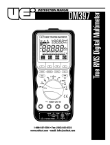
International Symbols
DM397-MAN P. 1

Rotary Switch
To turn the meter on, turn the rotary switch from the OFF position to
any switch setting.
If you want to view the full display (all segments illuminated), press and
hold the “HOLD” push-button while turning the meter on. Release the
button to return to normal viewing.
Turn the meter on by selecting any measurement function. The meter
presents a standard display for that function (range, measurement units,
on screen menu, etc.). The display may also show other information
based on the choices made through the on-screen
menu selection.
Use the on screen menu selection or the other push-buttons to select
any rotary switch alternative function.
When you turn the rotary switch from one function to another, a display
for the new function appears. Button choices made in one function do
not carry over into another function.
OFF: Turns the meter off. Setup parameters and stored
measurements are saved.
mV: Select either Millivolt AC RMS or DC Voltage measurements.
Compatible with various adapters.
V: Volts AC RMS, Volts DC, Volts AC+DC total RMS,
Volts AC/DC dual display, dBm and dB.
Hz: Frequency measurement. Duty cycle and pulse width are
also displayed if they are selected with the on-screen menu.
Ω : Access to resistance measurement, continuity test and
capacitance measurement. Conductance (1/Ω) is also dis
played in the secondary display when measuring resistance.
: Diode measurement (Forward bias voltage drop).
Temp: Temperature measurement in degrees Fahrenheit
or Centigrade.
µA: Select from Microamp AC RMS, Microamp DC, Microamp
AC+DC total RMS, and Microamp AC/DC dual display.
A: Select from Amperes AC RMS, Amperes DC, Amperes
AC+DC total RMS, and Amperes AC/DC dual display.
mA: Select from Milliamps AC RMS, Milliamps DC, Milliamps
AC+DC total RMS, and Milliamps AC/DC dual display.
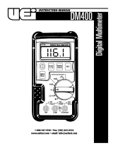
C o n t rols and Indicators
1. Digital Display: Readings are displayed on a 4-4/5 digit,
50,000 count (primary display) and 5,000 count
(secondary display).
2. Rotary Switch: Used to turn the power on or off and to select
a function.
3. On Screen Menu Selection Push-buttons: Used to select
functions from the on screen menus.
4. Special Function Push-buttons: Used to select special
functions and features.
5. Input Terminal 10A: (20A for 30 sec.) current
measurement function.
6. Input Terminal for Milliamp: (mA) and micro amp (µA)
current measurement function.
7. Common Input Terminal: (Ground reference) for all
measurement functions.
8. Input Terminal for Multiple Functions: Input jack for all
measurements except current (A, mA, µA) measurement functions.
9. RS-232 Optical Interface: Allows connection to a computer.
6
DM397-MAN P. 2
5
2
8
7
4
3
1
9

User-Friendly Rotary Switch Selections
DM397-MAN P. 3

Push-Buttons
RANGE: Use the “RANGE” push-button to manually select a range.
Press and hold the “RANGE” push-button for two seconds to return
the meter to auto range mode.
The meter is in auto range mode when the “AUTO” indicator is on.
The range and units are displayed on the LCD.
MIN/MAX: Press this button to scroll through the minimum,
maximum and average values. The minimum (MIN) reading is
displayed first and this mode calculates an average (AVG) of all
readings taken since the mode was activated. The meter beeps
when a new maximum or minimum reading is updated.
In the MIN/MAX mode, the primary display continues to show the
present measurement value.
Auto Power Off feature will be disabled automatically in this mode.
1mS Peak: Press this button momentarily to activate the 1mS peak
hold mode to capture transient voltage or current signal events as
short as 1mS with its display resolution of 5,000 counts. The LCD
displays the “1mS” and “MAX” indicators at the upper left corner
and - and “EXIT” indicators in the on screen menu selection. In this
mode the meter will display the captured maximum value. Press
the - menu key and the LCD will now display “1mS” and “MIN”
indicators and “+” and “EXIT” indicators on screen. In this mode
the meter will display the minimum captured value. Press the “+”
menu key to capture a maximum value again if desired. The meter
will beep when a new maximum or minimum reading is updated.
Press either the “1mS PEAK” push-button or the “EXIT” menu key
to exit the 1mS peak hold mode. Auto Power Off feature is disabled
in this mode.
REL ∆: Use this push-button to set the meter to relative (REL∆)
mode and make relative measurements. The reference value for the
REL∆ measurement can be a measured, or a programmed value. The
reference value
appears in the secondary display and the difference
value appears in the primary display.
<REL∆ to a Measured Value> - When you take the measurement
and the meter settles on the value, press this button. Subsequent
readouts will then be a difference from this reference value to the
new reading. This is useful for very low resistance values to
eliminate test lead resistance, or when observing a change from
a stable reading.
< R EL∆ to a Programmed Value> - Set the meter to the measurement
function and range you want and then press the “REL∆“ push-button.
While the meter is in REL∆ mode, press the “MIN/M A X” push-button
then the setup menu appears. Use the on screen menu selection
buttons to edit the desired reference value and then press the menu
button “4” for “EXIT” .
For subsequent readouts the programmed reference value is
subtracted from the actual measurement. The programmed
reference value is lost when the meter is turned off.
To exit REL∆ mode, press the “REL∆” push-button.
HOLD: Press this button to turn the “HOLD” mode on or off. When
the hold mode is activated, the meter beeps, freezes the display and
displays the “HOLD” indicator on the LCD. Hold mode freezes the
display for later view.
Auto Hold - To activate “AUTO HOLD” mode, press the “HOLD”
push-button two times until “A” and “HOLD” indicators appear
on the LCD.
NOTE: This mode is not available for capacitance measurements.
In this mode, the display automatically freezes and the meter beeps
when the measurement reading is stabilized. The display value will
be updated when a new measurement value is stabilized.
This mode is very useful when it is impossible for you to press the
“H
OLD” push-button or see the meter display while probing and
taking measurements.
MEM: Use the memory mode to store and recall measurement values.
Press the “MEM” button momentarily in order to activate the
memory mode. The display shows four menu selections: store, recall,
clear and exit.
STORE: Select “STORE” to store the held value in the next available
m e m o r y location. The memory location number momentarily shows on
the secondary display. If no memory locations are available, FUL L s h o w s
on the secondary display for two seconds and nothing is stored. You must
clear the memory locations using the “CL EA R” key in order to store the
held value.
RECALL: Select “RECALL” to review the stored value using the
menu key. The secondary display shows the value stored in that
location. Whenever you press “+” or “-
” menu key, the next or
previous stored value will be shown in the primary display and
the secondary display momentarily shows the corresponding
memory location.
CLEAR: Select “CLEAR” to clear all the stored values. When you
press the “CLEAR” key, the meter will ask you with the display of
“You Sure” along with the on screen menu selections of “AC”
(stands for All Clear), “CLEAR” and “EXIT”. When you press the
“CLEAR” key, the displayed value in the primary display is erased.
When you press the “AC” key, all the stored values are erased and
the word “Done” shows on the display. Press “EXIT” to exit the
memory mode without erasing the stored values.
EXIT: Select “EXIT” to exit memory mode. You can also exit
memory mode by pressing “MEM” push-button or turning the
rotary dial position.
(Backlight): Press the “MEM” ( ) push-button until the
backlight is turned on or off.
DM397-MAN P. 4

On Screen Menu Selection Keys
Each setting of the rotary switch to a measurement function position
may activate one or more menu selection key settings on the LCD. If
there is more than one measurement for a rotary switch setting, a menu
appears on the display. Press the corresponding menu selection key to
select the desired measurement.
Setup Mode
The setup mode allows you to customize default settings. To activate
the Setup Mode, press the menu Key “4” while the display shows all
segments on at power on reset.
You can customize the following default settings in sequence during the
setup cycle. The newly customized default values in any setup can be
saved only when the entire setup cycle is completed. The meter displays
“SAVE” at the end of the entire setup cycle. The setup values are stored
so they will become the new defaults and are not reset after power off.
• Enable or Disable The Auto Power Off Mode
The meter displays “AtP” in the secondary display, “EnbL” or
“DiSA” in the primary display and “+”, “-” and “EXIT” in the on
screen menu selection. You can toggle “EnbL/DiSA” by pressing
the “+” or “-” menu keys. Press the “EXIT” menu key to get into
the next setup screen
• Auto Power Off Time (in minutes)
If the auto power off is set to “EnbL” in the first step, the display
will now allow you to choose the time until the meter
automatically powers off. The display will show “MIN” in the
upper left corner and “AtP” in the secondary display, and a
two-digit number in the primary display. Adjust the time until
auto power off using the “+”, “-” and “<-” menu selection keys
to a number between 1 and 60. Press the “EXIT” menu key for
the next setup selection
• Backlight Auto-Off Time (in seconds)
The meter will display “LitE” in the
secondary display, a two-digit
number in the primary display and “+”, “-”, “<-” and “EXIT” in
the on screen menu selection. You can setup a new backlight
auto-off time (in seconds) by using the menu keys to select a
number between 1 and 60. Press the “EXIT” menu key for the
next setup selection
• Enable or Disable The Power Saving Mode Beep Alert
The meter displays “PALt” in the secondary display, “OFF” or
“ON” in the primary display and “+”, “-” and “EXIT” in the on
screen menu selection. You can toggle “OFF/ON” by pressing the
“+” or “-” menu keys. Press the “EXIT” menu key for the next
setup selection
• Enable or Disable Backlight When Meter Is Powered On
The meter displays “InIL” in the secondary display, “OFF” or
“ON” in the primary display and “+”, “-” and “EXIT” in the on
screen menu selection. You can toggle “OFF/ON” by pressing the
“+” or “-” menu keys. Press the “EXIT” menu key for the next
setup selection
• Enable or Disable The Beep Alert Warning For Over Range
The meter displays tone in the secondary display, “OFF” or “ON”
in the primary display and “+”, “-” and “EXIT” in the on screen
menu selection. You can toggle “OFF/ON” by pressing the “+”
or “-” menu keys. Press the “EXIT” menu key for the next
setup selection
• Enable or Disable The Beep Alert Warning For Incorrectly
Connected Test Leads
The meter displays “LALt” in the secondary display, “OF
F” or
“ON” in the primary display, a and “+”, “-” and “EXIT” in the on
screen menu selection. You can toggle “OFF/ON” by pressing the
“+” or “-” menu keys. Press the “EXIT” menu key in order to
save the customized default values entered during the setup
cycle. The meter will return to normal operation after the
message “SAVE” is displayed in the primary screen.
Use the menu selection keys in order to edit setup values as shown
below.
RS-232C PC to Meter Communications
The meter is equipped with an optically isolated interface port at the top
for data communication. The RS70 optical adapter cable and the WS70
software disc are required to connect the meter to the PC. The meter
includes these standard accessories. Refer to the READ ME file in the
WS70 for further details.
DM397-MAN P. 5
Press to
increase
setting value
Press to
decrease
setting value
Press to step
to next digit in
setting value
Press to move
to next setup.
Press to save
all setting and
exit setup
mode when
setting is
ended
Function
Key
EXIT
-
+

Operating Instructions
Making Measurements
All measurements are made by first setting the function knob to a specific
setting (the meter will select the default function for that position) and
then select a measurement using the menu keys. Note that not all func-
tion knob settings have a corresponding menu selection option.
For example, the steps below show how to take a DC voltage measurement.
1. Set the measurement knob to V for a voltage measurement.
NOTE: The default for this range is AC voltage.
2. Select the menu key 2 change to DC voltage (Fig 1).
3. Connect the test leads to the correct input jacks (COM, VΩ, ,
, TEMP).
Voltage (mV, V) Measurements
Ranges available in volts functions are:
• mV
50.000mV, 500.00mV DC and 500.00mV AC
• V
5.0000V, 50.000V, 500.00V, 1000.0V
*dBm readout = 10 x log (primary display readout 2/r), where R = 600Ω (default)
db readout = 20 x log (primary display readout / ref), where ref = 1V (default)
This meter has high impedance circuitry (10MΩ) for measuring voltage.
AC Voltage Measurement
All push-button features are available in this function. The on screen
menu selection accesses decibel (dBm or dB) measurements.
dB (dBm or dB V) measurements in AC volts function.
The AC volts function allows you to display readings as deviations in dB
(d
ecibels) above or below an established reference level.
Set up dB measurements by using the on screen menu selection buttons
when measuring AC volts. The dBm (or dB V) value appears in the
s e c o n d a ry di splay and the AC reading appears in the primary display.
Normally dB is measured as dBm, which is a measure of decibels relative
to 1 milliwatt. The meter assumes a resistance of 600Ω in making this
calculation. This resistance can be set for any value from 1Ω to 1, 9 9 9 Ω
by using the setup menu selection buttons. When measuring dB V, the
reference voltage can be set for any value from 0.1000V to 5.0000V by
using the setup menu.
DC Voltage Measurement
All push-button features are available for a standard DC voltage reading.
Both AC and DC voltage measurements.
When a DC volts function is selected, the meter can display the combined
AC+DC (RMS) value or AC and DC components of a signal separately by
using the on screen menu selections.
When the meter shows AC over DC (AC voltage in the primary and DC in
the secondary display), the other push-button functions except “RA NGE”
are not available.
A p p l i cations: Using AC+DC in
AC/DC volts mode
To take the combined AC+DC total RMS volts measurement, press menu
key 4. In the above example the total RMS value of 6.118 V shows on the
primary display and the frequency of 60.00 Hz shows on the secondary
display. When calculating the power dissipated in a circuit component, it
is critical that the DC value is factored into the equation V
rms
x I
rms
where V
rms
is AC+DC total RMS.
DM397-MAN P. 6
(Fig 1)
Measurement
DC millivolts
(default)
AC
Menu key
(no selection)
AC
Connect Le a d s P r i m a ry Display
DC
AC
S e c o n d a ry Display
-
Hz
Measurement
True RMS AC
Voltage
(default)
DC Voltage
dBm
dB
AC+DC total
RMS
AC+DC dual
display
Menu key
(no selection)
DC
dBm or dB
(press to
toggle)
AC+Dc or
AC+DC (press
to toggle)
Connect Le a d s P r i m a r y Display
AC
DC
AC
DC
AC+DC
AC
S e c o n d a r y Display
Hz
-
dBm
dB
Hz
DC
dB = 20 x log (Vx ÷Vr )
• For dBm, Vr is the voltage across the reference resistance
at 1 milliwatt. For example, Vr would be 0.77 46 V with a
600 reference resistance.
• For dB V, the reference voltage is 1 V.
DC = 6 V
AC = 1.2 Vrm
Frequency = 60 Hz

Another useful feature of this meter is AC/DC dual display mode. AC
voltages riding on power supplies can cause problems with electronic
circuits. If the meter is set to DC volts mode, the display shows the DC
component of 6.0000V. However, the AC component may be missed. It
is recommended that you set the meter to AC/DC dual display mode by
pressing menu key 4 twice. The primary display shows the 1.2000 V AC
and the secondary display shows the 6.000 V DC. This is a method to
take both the AC and DC readings on a source without changing the
meter settings.
Frequency (Hz) Measurements
The meter auto-ranges to one of six frequency ra n g e s :
NOTE: The 1mS Peak push-button cannot be used in the frequency
mode. The meter will beep to indicate this when the 1mS Peak
push-button is pressed.
• The meter defaults at negative edge triggering in the frequency
measurement mode - You can select positive edge by pressing
menu key 4. The secondary display will indicate either “EdGE”
for positive or “-EdGE” for negative
Duty Cycle Measurement
D u ty c ycle (or duty factor) is the percentage of time signal is above or
b e l ow a trigger level during one cy c l e .
The duty cycle mode is optimized for measuring the ON and OFF time of
logic and switching signals. Systems such as electronic fuel injection and
switching power supplies are controlled by varying pulse-widths which
can be checked by measuring the duty cy c l e .
Positive and Negative Duty Cycle
To measure duty cycle, set duty cycle to either positive or negative by
using menu key 4. When you measure negative duty cycle a “-” symbol
s h ows in the secondary displ
ay.
Measure Positive Duty Cycle
Pulse Width Measurement
The pulse width measurement function allows you to measure the
amount of time a signal is high or low within a given period. The
measured waveform must be periodic.
Resistance (Ω, , ) Measurement
(Ohms, Continuity and Capacitance)
CAUTION!
To avoid damaging the meter or the equipment under test, remove all
power from the circuit and discharge all high-voltage capacitors before
measuring resistance.
The available resistance ranges are 50 . 0 0 0Ω, 50 0 . 0 0 Ω, 5.0000kΩ,
50 . 0 0 0 kΩ, 50 0 . 0 0 kΩ, 5.0000MΩ and 50 . 0 0 0 MΩ.
Tips for measuring resistance:
• Because the meter’s test current flows through all possible paths
between the test probe tips, the measured value of a resistor in a
circuit is often different from the resistor’s rated value
• The test leads can add 0.1Ω to 0.2Ω of error to resistance
measurements - To measure the resistance of the leads, touch the
probe tips together and read the resistance - If necessary, you
can press the “REL∆” push-button to automatically subtract
this value
• The resistance function can produce enough voltage to
f o rward-bias silicon diodes or transistor junctions causing them
to conduct to avoid this, and possibly damaging circuit components -
Do not use the 50 MΩ range for measuring in-circuit resistance
DM397-MAN P. 7
Measurement
Frequency
Frequency
and duty
cycle dual
display
Frequency
and pulse
width dual
display
Menu key
(no selection)
%
ms
Connect Le a d s P r i m a ry Display
Hz
Hz
Hz
S e c o n d a r y Display
-EdGE
Duty Cycle (%)
Pulse Width (ms)
Measurement
Resistance
(default)
Continuity
Capacitance
Menu key
(no selection)
Connect Le a d s
P r i m a ry Display
Ω
Ω
Ω
S e c o n d a ry Display
S
(conductance)
OPEn or Short
(beeps on short)
-

Continuity Test
The continuity function detects intermittent opens and shorts lasting as little
as 1 millisecond. These brief contacts cause the meter to emit a short beep.
This function is convenient for checking wiring connections and opera t i o n s
of switches. A continuous tone indicates a complete wire or connection.
CAUTION!
Using resistance and continuity function in a live circuit will produce
false results and may damage the instrument. In many cases the
suspicious components must be disconnected from the circuit under
test to obtain accurate results.
The 1mS Pe a k , MIN/M AX and REL∆ functions are not available when
c o n t i n u i t y is selected
Conductance for High Resistance Tests
Conductance is the reverse of resistance, and is the ability of a circuit to
pass current. High values of conductance correspond to low values or
resistance. The unit of conductance is the Siemens (S).
Capacitance Measurement
CAUTION!
To avoid damaging the meter or the equipment under test, remove all
power from the circuit and discharge all high-voltage capacitors before
measuring capacitance.
Large value capacitors should be discharged
through an appropriate resistance load. use the DC voltage function to
confirm that the capacitor is discharged.
The available capacitance ranges are 5nF, 50nF, 500nF, 5µF, 50µF, 50 0 µ F ,
and 5mF (5000 microfara d s ) .
Tips for measuring ca p a c i t a n c e :
• To speed up measurements of similar values, press “RANGE”
push-button to manually select the proper range
• To measure small values of capacitance accurately, press “REL∆“
push-button with the test leads open to subtract the residual
capacitance of the meter and test leads
Diode ( ) Test
CAUTION!
D i s c h a rge all high - v o l t a ge c apacitors before testing diodes. La r ge value
capacitors should be discharged thro u g h an appropriate resistance load.
Use the diode test to check diodes, transistors, silicon controlled rectifiers
( S C Rs), and other semiconductor devices. The test sends a current
through a semiconductor junction, and then measures the junction’s
voltage drop.
Forward Biased Reading: Normal forward voltage drop (forw a r d i n g
biased) for a good silicon diode is between 0.4V and 0.9V. A reading
higher than that indicates a leaky (defective) diode. A zero reading
i n d i cates a shorted (defective) diode. A reading of “o F L” indicates an
open diode (defective).
Reverse Biased Reading: Reverse the test leads across the diode. The
display should show “o F L” if it is good. Any other readings indicate the
diode is shorted or resistive (defective).
Temperature (Temp) Measurements
WARNING!
Do not apply thermocouple to circuits exceeding 30V RMS 42.4V peak or
60V DC.
*Use the ATT70, Temperature probe adapter with standard K-type thermocouples.
Observe proper polarity.
Current ( , ) Measurements
WARNING!
Never attempt an in-circuit current measurement where the open-circ u i t
potential to earth is greater than 10 0 0 V. You may damage the meter or
be injured if the fuse blows during such a measure m e n t .
CAUTION!
Check the meter fuses before measuring current. Use the proper termi-
nals, function, and ra n g e for current measurements. Never place the
p r obes in parallel with any circuit or component when the test leads are
p l u g ged into the current terminals.
The available current ranges are 500.00µA, 5000.0µA, 50 . 0 0 0 m A ,
500.00mA, 5.0000A and 10 . 0 0 0 A .
*I RMS = (AC+DC total RMS amps)
DM397-MAN P. 8
Measurement
Diode
Menu key
(no selection)
Connect Le a d s P r i m a ry Display
V
S e c o n d a r y Display
-
Measurement
Celsius Temp.
(default)
Fahrenheit
Temp.
Menu key
(no selection)
SET
Connect Le a d s P r i m a ry Display
C
F
S e c o n d a r y Display
-
-
Measurement
True RMS
AC Amps
(default)
DC Amps
AC+DC
Total RMS
AC/DC
Dual Display
Menu key
(no selection)
DC
AC+DC
or
AC/DC
(press to
toggle)
Connect Le a d s P r i m a ry D isplay
A C
D C
A C + D C
A C
S e c o n d a ry Display
H z
-
H z
D C

To Measure AC or DC Current
1. Turn off power to the circuit and discharge all high-voltage ca p a c i t o r s .
2. Insert the black lead into the “COM” terminal and the red lead
into an input terminal appropriate for the measurement range.
NOTE: To avoid blowing the meter’s 440mA fuse, use the mAµA
terminal only if you are sure that the current is less than 400mA. It is
best to start in the higher ra n ge when unsure to take the initial
m e a s u r ement. 400mA is displayed as 0.4000A in the 5.000A ra n ge .
3. Open the circuit path to be tested.
4. Touch the red lead to the more positive side of the break and the
black lead to the more negative side. (Reverse connections will
only display a negative reading for DC current, but will not
damage the meter).
5. Turn on the power to the circuit and read the display.
6. After measuring the current, turn off power to the circuit and
discharge all high-voltage capacitors.
7. Disconnect the meter and restore the circuit to normal operation.
Wrong Input Warning Feature
If the display shows “L EA d” or “FUSE”, be sure the meter is set up
correctl
y and test the meter’s fuses as described under Auto Fuse
D e t e c t i o n. If the rotary switch is not correctly set to one of the current
measuring positions, the beeper warns you by making a chirping sound.
This warning is intended to stop you from attempting a measurement other
than current when the test leads are plugged into a current terminal.
Placing the probes in parallel with a powered circuit when the leads are
plugged into a current terminal can damage the circuit you are testing and
b l ow the meter’s fuses. This is due to the fact that in the current range the
resistance through the amps terminals is low, and the meter acts like a
shor
t to your circuit.
Auto/Manual Range Operation
Press the “RANGE” push-button momentarily to select manual and the
meter will stay in the range it is in when the LCD icon “AUTO” turns off.
Press the button momentarily again to step through the ranges. Press
and hold the “RANGE” push-button for two seconds or more to
resumes auto ranging.
Auto Power Off
The auto power off feature has two steps. The first step has the meter
automatically go to the power saving mode to extend the battery life
after approximately 15 minutes with no activity. When the meter enters
this mode, the meter beeps waring tones every minute. To turn on the
meter, press any button or move the rotary switch to any position. The
second step is to automatically turn the meter completely off. This
occurs approximately 15 minutes after the meter entered the power
saving mode. To turn the meter back on after a complete power off you
must rotate the selector to OFF, and then to the required range.
You can disable auto power off by using the setup menu. Both the auto
off time and the power saving mode beep alert time can be adjusted
from the setup menu.
M a i n t e n a n c e
Periodic Service
WARNING!
Repair and service of this instrument is to be performed by qualified
personnel only. Improper repair or service could result in physical
degradation of the meter. This could alter the protection from
electrical shock and personal injury this meter provides to the
operator. Perform only those maintenance tasks that you are
qualified to do.
These guidelines will help you attain long and reliable service from
your meter:
• Calibrate your meter annually to ensure it meets original
performance specifications
• Keep your meter dry. If it gets wet, wipe dry immediately.
Liquids can degrade electronic circuits
• Whenever practical, keep the meter away from dust and dirt
that can cause premature wear
• Although your meter is built to withstand
the rigors of daily use,
it can be damaged by severe impacts. Use reasonable caution
when using and storing the meter
Cleaning
Periodically clean your meter’s case using a damp cloth. DO NOT use
abrasive, flammable liquids, cleaning solvents, or strong detergents as
they may damage the finish, impair safety, or affect the reliability of the
structural components.
Clean the input terminals as follows:
1. Turn the meter off and remove all test leads.
2. Shake out any dirt that may be in the terminals.
3. Soak a new swab with alcohol and work the swab around in
each terminal.
DM397-MAN P. 9
Rotary Switch
µA
A
mA
I n p u t
mAµA
mAµA
A
R a n g e s
500.00µA, 5000.0µA
50.000mA, 500.00mA
5.0000A, 10.000A
-

Battery and Fuse Replacement
Always use a fresh replacement battery of the specified size and type.
Immediately remove the old or weak battery from the meter and
dispose of it in accordance with your local disposal regulations. Batteries
can leak chemicals that corrode electronic circuits. If your meter is not
going to be used for a month or more, remove and store the battery in
a place that will not allow leakage to damage other materials.
Auto/Manual Range Operation
Press the “RANGE” push-button momentarily to select manual and the
meter will stay in the range it is in when the LCD icon “AUTO” turns off.
Press the button momentarily again to step through the ranges. Press
and hold the “RANGE” push-button for two seconds or more to
resumes auto ranging.
WARNING!
Disconnect the test leads from the circuit under test and from the meter
prior to removing or installing batteries.
Auto Fuse Detection
The meter automatically verifies the integrity of the fuses when you set
the rotary function knob to the amps or milliamps range and plug a test
lead into either the “A” or the “mAµA” terminal. In either case, if an
open fuse is detected, the word “FUSE” shows on the primary display.
To install a new battery or fuse, follow these procedures:
1. Turn the rotary switch to OFF and remove the test leads from the
input terminals.
2. Remove the screw and press above where indicated on back of
meter to remove the cover.
3. Remove old battery of fuse and replace with specified new ones.
4. Reinstall battery cover and screw.
WARNING!
Under no circumstances should you expose batteries to extreme heat or
fire as they may explode and cause injury.
Tro u b l e s h o o t i n g
Always check the battery and fuses when you encounter trouble. Also
inspect the test leads for breaks or damage and replace if damage
is visible.
If the meter’s V/Ω input terminal has been subjected to high voltage
transients (caused by lightning or switching surge to the system under
test) by accident or abnormal operating conditions a series fusible
resister may be blown. These are circuit components that are designed
to open in the event of transients to protect the user and the meter.
Most measuring functions through the terminal will then be open and
not functional.
If this occurs, the series fusible resistor and spark gaps should be
replaced by qualified personnel. Refer to the limited warranty section
for obtaining warranty or repair service.
S p e c i f i c a t i o n s
Safety and Compliance
Physical Specifications
DM397-MAN P. 10
Maximum voltage between 1000V AC/DC
any terminal and earth ground
Compliance Complies with CSA C22.2 No 1010.1-92, ASNI/ISA-S82,
01-94 to 1000V over voltage CAT III
Certifications UL & cUL standard UL 3111-1 listed
CE-marking certified
Surge protection 8kV peak per IEC 1010.1-92
Fuse protection fro mA or µA 1000V / 440 mA IR 10 kA fast fuse
inputs
Fuse protection for A input 1000V / 11 A UR 10 kA fast fuse
Display (LCD) 50,000 count digital primary
5,000 count secondary
Updates 4/sec. nominal
Analog - 25 segments, updates 40/sec.
Operating temperature 32˚ to 122˚F (0˚ to 50˚C)
Storage temperature -4˚ to 140˚F (-20˚ to 60˚C)
Temperature coefficient Nominal 0.15 x (specified accuracy)/˚C @
(0˚ to 18˚C or 28˚ to 50˚C) Otherwise as specified
Relative Humidity 0% to 80% @ 32˚ to 95˚F
0% to 70% @ 96˚ to 122˚F
Altitude Operating - up to 6,500 feet (2,000 m)
Storage - up to 32,000 feet (10,000 m)
Battery type Single 9V battery - NEDA 1604, JIS 006P or IEC 6F 22
Battery life 150 hrs. typical (with backlight off)
Shock vibration Per MIL-T-PRF 28800 for Class II instruments
Pollution degree 2
Electromagnetic capability Susceptibility - commercial limits for EN 50082-1
(EMC) Emissions - commercial limits for EN 50081-1
Size (H x W x D) 8.2” x 4.1” x 2.1” (208 x 103 x 54 mm)
Weight Approximately 1.44 lb (655 g)
Warranty 5 years
Calibration interval 1 year

Feature Summary
DC Voltage
NMRR : >60dB @ 50/60 Hz
CMRR : >120dB @ DC, 50/60 Hz, Rs = 1k
Input impedance : 10MΩ, 30 pF nominal
(50MΩ, 100 pF nominal for 50m V
& 500mV ranges)
AC Voltage
CMRR : >60dB @ DC to 60 Hz, Rs = 1kΩ
Input impedance : 10MΩ, 30 pF nominal
(50MΩ, 100 pF nominal for 500m V range)
DC Current
AC Current
(AC+DC) Voltages and (AC+DC) Current
Resistance
Open Circuit Voltage: <1.3 V DC
*1.
Using relative (REL∆) mode
Conductance (5,000 counts only)
DM397-MAN P. 11
Backlight For clear readings in poorly lighted areas
Fast auto ranging Meter automatically selects the best range quickly
AC+DC total RMS Choices for AC only, AC+DC readings or AC and DC
(@40Hz to 10 kHz) Dual display
DBm, dBV User selectable impedance references for dBm
User selectable voltage references for dBV
Auto HOLD Holds readings on display
Continuity/Open test Beeper sounds
Fast analog bar graph 25 segments for view of fast events and trends
Memory locations 20
Duty cycle/pulse width Measures the time that the signal is ON or OFF in % or
milliseconds
MIN/MAX mode Record maximum, minimum and average values
1mS PEAK mode Captures peaks of 1 millisecond
Close-case calibration No internal adjustment necessary
Batter/fuse access door Battery or fuse replaceable without voiding calibration
High-impact over molded case Protective feature for the meter and user
Range Resolution Accuracy
50 mV 1 µV 0.05% + 10
500 mV 10 µV
5 V 100 µV 0.05% + 2
50 V 1 mV
500 V 10 mV
1000 V 100 mV 0.1% + 2
Range Resolution Accuracy
40Hz - 1kHz 4kHz - 5kHz 5kHz - 20z 20kHz - 50kHz
500 mV 10 µV 0.3%+10 1.0%+10 2.0%+20 Unspecified
5 V 100 µV
50 V 1 mV 0.3%+10 0.5%+10 0.5%+10 0.8%+20
500 V 10 mV
1000 V 100 mV 0.4%+10 0.5%+20 Unspecified Unspecified
Range Resolution Accuracy
500 µA 10 nA
5 mA 100 nA 0.1% + 5
50 mA 1 µA
500 mA 10 µA
5 A 100 µA 0.3% + 10
10 A 1 mA 0.3% + 20
Range Resolution Accuracy
40Hz - 1kHz 1kHz - 10kHz
500 µA 10 nA
5 mA 100 nA 0.3% + 5 0.8% + 10
50 mA 1 µA
500 mA 10 µA
5 A 100 µA 0.4% + 10 Unspecified
10 A 1 mA 0.4% + 20
Function Range Resolution Accuracy
40Hz - 1kHz 1kHz - 10kHz
DC mV 500 mV 100 µV 0.5% + 5 0.8% + 5
5 V 1 mV
DC V 50 V 10 mV 0.5% + 3 0.8% + 3
500 V 100 mA
1000 V 1 V 0.8% + 5 0.8% + 5
DC µA 500 µA 100 nA
5 mA 1 µA 0.5% + 3 1.0% + 5
DC mA 50 mA 10 µA
500 mA 100 µA
DC A 5 A 1 mA 0.8% + 10 Unspecified
10 A 10 mA
Range Resolution Accuracy
50 Ω 0.001 Ω 0.5% + 20 *
1
500 Ω 0.01 Ω 0.1% + 5 *
1
5 kΩ 0.1 Ω
50 kΩ 1 Ω 0.1% + 2
500 kΩ 10 Ω
5 MΩ 100 Ω 0.3% + 5
50 MΩ 1 kΩ 0.5% + 20
Range Resolution Accuracy
50 nS 0.01 nS 0.1% + 10

Continuity
Diode Test
Capacitance (5,000 counts only)
*1.
Accuracy with film capacitor or better
*2.
Using Relative (REL∆) mode
Frequency, Duty Cycle, Pulse Width and Temperature
dBm and 1mS PEAK Hold (5,000 counts only)
Burden Voltage (A, mA, µA)
G l o s s a r y of Te r m s
Average sensing RMS calibrated: RMS (Root-Mean-Square) is the
term used to describe the effective or equivalent DC value of an AC
signal. Most digital multimeters use average sensing RMS calibrated
technique to measure RMS values of AC signals. This technique is to
obtain the average value by rectifying and filtering the AC signal. The
average value is then scaled upward (that is, calibrated) to read the
RMS value of a sine wave. In measuring pure sinusoidal waveforms this
technique is fast, accurate and cost effective. However, in measuring
non-sinusoidal waveforms significant errors can be introduced because
of the different scaling factors involved with changing average to
RMS values.
True RMS: True RMS is a term which identifies a DMM that accurately
responds to the effective RMS value regardless of the waveform shapes
such as square, saw tooth, triangle, pulse trains, spikes and transient
glitches as well as distorted waveforms with the presence of harmonics.
Non-sinusoidal waveforms may cause:
• Overheating transformers, generators and motors to burn out
faster than normal
• Circuit breakers to trip prematurely
• Fuses to blow
• Neutrals to be overheated due to the triplen harmonics present
on the neutral
• Bus bars and electrical panels to vibrate
Crest Factor: Crest Factor is the ratio of the Crest (instantaneous peak)
value to the True RMS value, which is commonly used to define the
dynamic range of a True RMS DMM. A pure sinusoidal waveform has a
crest factor of 1.414. A badly distorted sinusoidal waveform normally has
a much higher Crest Factor.
NMRR (Normal Mode Rejection Ratio): NMRR is th
e DMM’s ability
to reject unwanted AC noise effect, which can cause inaccurate DC
measurements. NMRR is ty p i c ally specified in terms of dB (decibel). This
meter has a NMRR specification of >60 dB at 50Hz / 60Hz, which provides
the ability to reject the effect of AC noise in DC measurements.
CMRR (Common Mode Rejection Ratio): Common mode voltage is
voltage existing on both the COM and Voltage input terminals of a DMM
with respect to ground. CMRR is a DMM’s ability to reject common
mode voltage effect, which can cause digit rattle or offset in voltage
measurements. This meter has a CMRR specification of >60 dB at DC to
60 Hz in AC volts measurement function and >120 dB at DC, 50Hz and
60Hz in DC volts measurement function.
DM397-MAN P. 12
Audible threshold: The beeper sounds if the measured resistance is lower than 10 Ω,
and turns off when greater than about 70 Ω.
Response time: < 1 m sec.
Range Accuracy Test Current (typical) Open Circuit Voltage
4 V 2% + 1 1 mA <3.0 V DC
Range Resolution Accuracy *
1
5 nF 1 pF 1.0% + 5 *
2
50 nF 10 pF 1.0% + 3 *
2
500 nF 100 pF
5 µF 1 nF 2.0% + 3
50 µF 10 nF 3.0% + 3
500 µF 100 nF
5000 µF 1 µF 3.5% + 5
Function Range Resolution Accuracy
Frequency 50 Hz 0.001 Hz
[Minimum 500Hz 0.01 Hz
Frequency: 5 kHz 0.1 Hz 0.002% + 3
0.5 Hz 50 kHz 1 Hz
sensitivity 500 kHz 10 Hz
250 mV] 5 MHz 100 Hz
Duty Cycle 0.1% to 99.9% 0.1% 0.5 Hz to 300 kHz (pulse width > 3 µ sec.)
(0.1% + 0.05% per kHz+1 count) for 5 V
input (Logic signals only)
Pulse Width Input Frequency Pulse width > 3µs
0.5 Hz to 300 kHz
Temperature -58˚ to 2.372˚F 0.1˚F with k-type thermocouple
(-50˚ to 1.300˚C) (0.1˚C) ±5.4˚F (±3˚C) typical
Function Characteristics Accuracy
Selectable reference impedance of ±0.25 dB + 2 digits
dBm 1 to 1,999 (@ 40 Hz to 20kHz)
At 600 : -11.76 dBm to 54.25 dBm
Input impedance: 10M, 30 pF nominal
1 mS PEAK Specified voltage or current measurement accuracy ±30 counts of the peak
value of a single 1 mS pulse.
Function Range Burden Voltage (typical)
500 µA 150 µV / µA
mA / µA 5000 µA 150 µV / µA
50 mA 3.3 mV / mA
500 mA 3.3 mV / mA
A 5 A 0.03 V / A
10 A 0.03 V / A

Burden Voltage: Burden voltage is a voltage drop across the input
terminals of a current measuring device, caused by internal shunt
resistance. Burden voltage contributes to the measurement error, and
should be as low as practical.
Temperature Coefficient: Temperature Coefficient is a factor used
to calculate the change in indication or output of an instrument with
changes in temperature. Un-compensated changes in temperature
contribute uncertainty by an amount determined by the temperature
coefficient of the instrument.
Analog Bar Graph: The analog bar graph provides a visual indication
of measurements similar to a traditional analog meter’s needle. It is
excellent in detecting faulty contacts, identifying potentiometer’s clicks
and indicating signal spikes during adjustments.
DM397-MAN P. 13

Limited Warranty
The DM397 is warranted to be free from defects in materials and workmanship for a period of
five years from the date of purchase. If within the warra n ty period your instrument should
become inoperative from such defects, the unit will be repaired or replaced at UEi’s option.
This warra n ty covers normal use and does not cover damage which occurs in shipment or
failure which results from alteration, tampering, accident, misuse, abuse, neglect or improper
maintenance. Batteries and consequential damage resulting from failed batteries are not
covered by warra n ty.
Any implied warranties, including but not limited to implied warranties of merchantability
and fitness for a particular purpose, are limited to the express warranty. UEi shall not be
liable for loss of use of the instrument or other incidental or consequential damages,
expenses, or economic loss, or for any claim or claims for such damage, expenses or
economic loss. A purchase receipt or other proof of
original purchase date will be required
before war
ra n ty repairs will be rendered. Instruments out of warra n ty will be repaired (when
r e p a i r able) for a service charge. Return the unit postage paid and insured to:
This warranty gives you specific legal rights. You may also have other rights which vary from
state to state.
DM397
True RMS Digital Multimeter
Copyright © 2007 UEi DM397-MAN 1/07
PLEASE
RECYCLE
99 Washington Street
Melrose, MA 02176
Phone 781-665-1400
Toll Free 1-800-517-8431
Visit us at www.TestEquipmentDepot.com
/