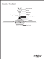
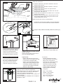
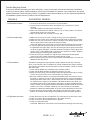
AireRyder FN52241 is a ceiling fan designed for residential use that comes with a dimmer and remote control, which allows you to adjust the fan speed and light intensity from a distance. The fan has five blades, a 52-inch blade span, and can be used with solid-state speed controls. It also includes a safety cable hook for added safety and should be mounted to an outlet box marked "Acceptable for Fan Support" using the provided mounting screws.
AireRyder FN52241 is a ceiling fan designed for residential use that comes with a dimmer and remote control, which allows you to adjust the fan speed and light intensity from a distance. The fan has five blades, a 52-inch blade span, and can be used with solid-state speed controls. It also includes a safety cable hook for added safety and should be mounted to an outlet box marked "Acceptable for Fan Support" using the provided mounting screws.


-
 1
1
-
 2
2
-
 3
3
-
 4
4
-
 5
5
-
 6
6
-
 7
7
-
 8
8


AireRyder FN52241 is a ceiling fan designed for residential use that comes with a dimmer and remote control, which allows you to adjust the fan speed and light intensity from a distance. The fan has five blades, a 52-inch blade span, and can be used with solid-state speed controls. It also includes a safety cable hook for added safety and should be mounted to an outlet box marked "Acceptable for Fan Support" using the provided mounting screws.
Ask a question and I''ll find the answer in the document
Finding information in a document is now easier with AI
Related papers
-
AireRyder FN52125BN-34 Installation guide
-
-
-
AireRyder FN52447OBB Installation guide
-
-
-
-
-
-
Other documents
-
Regency Fan Regulator Owner's manual
-
none X-RC6776 Installation guide
-
Bel Air Lighting F-1004 ROB Installation guide
-
 Kichler Lighting 337001WH User manual
-
Savoy ceiling fan Operating instructions
-
 Turn of the century 355-3003 Assembly And Installation Instructions
-
thdstatic Multiple Pendant Light User manual
-
Triarch 31900/1 User manual
-
 Yosemite Home Decor ADALYN-BBN Operating instructions
-
TroposAir 88704 Installation guide


