Page is loading ...

SD card real time datalogger, RS232/USB
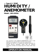
ENVIRONMENT METER
Model : ATE-9538
Your purchase of this
SOUND LEVEL METER
w i t h S D C A R D
DATALOGGER marks a
step forward for you
into the field of
precision measurement.
Although this METER is
a complex and delicate
instrument, its durable
structure will allow
many years of use if
p r o p e r o p e r a t i n g
t e c h n i q u e s a r e
developed. Please read
t h e f o l l o w i n g
instructions carefully
and always keep this
manual within easy
reach.
OPERATION MANUAL
www.tmatlantic.com

TABLE OF CONTENTS
1. FEATURES..................................................................1
2. SPECIFICATIONS........................................................
.
2
3. FRONT PANEL DESCRIPTION.......................................6
4. MEASURING PROCEDURE............................................7
4-1 Function selection .......................................................7
4-2 Anemometer/Temp. measurement................................8
4-3 Humidity/Temp. measurement......................................9
4-4 Li
g
ht measurement......................................................9
4-5 Type K/J Temperature measurement............................
.
10
4-6 Sound level measurement ( optional probe ).................
.
11
4-7 Data Hold....................................................................11
4-8 Data Record ( Max./ Min. readin
g
)...............................
.
12
4-9 LCD Backli
g
ht ON/OFF..................................................12
5. DATALOGGER.............................................................13
5-1 Preparation before execute datalo
gg
er function.............
.
13
5-2 Auto Datalo
gg
er ( Set samplin
g
time 1 second ).......≧ 14
5-3 Manual Datalo
gg
er ( Set samplin
g
time = 0 second )....15
5-4 Check time information................................................
.
15
5-5 Check samplin
g
time information..................................
.
16
5-6 SD Card Data structure................................................
.
16
6. Saving data from the SD card to the computer..............17
7. ADVANCED SETTING...................................................18
7-1 Set clock time
( Year/Month/Date, Hour/Minute/ Second )..............19
7-2 Decimal point of SD card setting.............................20
7-3 Auto power OFF management ...............................20
7-4 Set beep Sound ON/OFF........................................
.
21
7-5 Select the thermometer type to Type K or Type J....
.
21
7-6 Select the temperature unit to or .................℃℉ 22
7-7 Set sampling time .................................................22
7-8 SD memory card format.........................................22
8. POWER SUPPLY from DC ADAPTER..............................23
9. BATTERY REPLACEMENT.............................................23
10. SYSTEM RESET.........................................................24
11. RS232 PC serial interface...........................................24
12. Optional Type K Temp. probe....................................
.
26
13. PATENT....................................................................27

1. FEATURES
* Environment instrument, multi-function, all in one.
*
T
ype K/J thermometer, Humidity/Temp. meter,
Anemometer, Light meter, Sound level meter ( optional
adapter ).
* Humidity measurement show both %RH and Temp. .
* Anemometer can default the display unit to m/S, FPM,
Km/h, mph, knot.
* Light meter can default the display unit to LUX or Ft-cd.
* Thermocouple Thermometer can default to accept
type K or type J Temp. probe.
*
T
emp. display unit default to or .℃℉
* Meter can default auto power off or manual power off.
* Real time SD memory card Datalogger, it Built-in Clock
and Calendar, real time data recorder , sampling time set
from 1 second to 3600 seconds.
* Manual datalogger is available ( set the sampling
time to 0 ), during execute the manual datalogger
function, it can set the different position ( location ) No.
( position 1 to position 99 ).
* Innovation and easy operation, computer is not need
to setup extra software, after execute datalogger, just
take away the SD card from the meter and plug in the
SD card into the computer, it can down load the all the
measured value with the time information (
year/month/date/ hour/minute/second ) to the Excel
directly, then user can make the further data or graphic
analysis by themselves.
* SD card capacity : 1 GB to 16 GB.
* LCD with green light backlight, easy reading.
* Can default auto power off or manual power off.
* Data hold, record max. and min. reading.
* Power by UM3/AA ( 1.5 V ) x 6 batteries or DC 9V adapter.
* RS232/USB PC COMPUTER interface.
* Available for the HVAC applications.
1

2. SPECIFICATIONS
2-1 General Specifications
Circuit Custom one-chip of microprocessor LSI
circuit.
Display LCD size : 52 mm x 38 mm
LCD with green backlight ( ON/OFF ).
Measurement *Type K/J thermometer
Unit *Humidity/Temp. meter
*Anemometer with Temp.
*Light meter
*Sound level meter ( optional adapter )
Datalogger Auto 1 second to 3600 seconds
Sampling Time
@ For anemometer measurement,
Setting range
the sampling time setting value
should be 2 seconds.≧
@ Sampling time can set to 1 second,
but memory data may loss.
Manual Push the data logger button
once will save data one time.
@ Set the sampling time to
0 second.
@ Manual mode, can also select the
1 to 99 position ( Location ) no.
Memory Card SD memory card. 1 GB to 16 GB.
Advanced * Set clock time ( Year/Month/Date,
setting Hour/Minute/ Second )
* Decimal point of SD card setting
* Auto power OFF management
* Set beep Sound ON/OFF
* Set thermometer type to Type K or Type J
* Set temperature unit to or ℃℉
* Set sampling time
* SD memory card Format
2

Temperature Automatic temp. compensation for the
Compensation Anemometer function and the type K/J
thermometer.
Data Hold Freeze the display reading.
Memory Recall Maximum & Minimum value.
Sampling Time Approx. 1 second.
of Display
Data Output RS 232/USB PC computer interface.
* Connect the optional RS232 cable
UPCB-02 will get the RS232 plug.
* Connect the optional USB cable
USB-01 will get the USB plug.
Operating 0 to 50 .℃
Temperature
Operating Less than 85% R.H.
Humidity
Power Supply
*
A
Alkaline or heavy duty DC 1.5 V battery
( UM3, AA ) x 6 PCs, or equivalent.
*
A
DC 9V adapter input. ( AC/DC power
adapter is optional ).
Power Current Normal operation ( w/o SD card save
data and LCD Backlight is OFF) :
Approx. DC 15 mA.
When SD card save the data and LCD
Backlight is OFF) :
Approx. DC 36 mA.
Weight 515 g/ 1.13 LB.
Dimension Meter 135 x 60 x 33 mm.
Probe 105 x 46 x 29 mm.
Accessories * Instruction manual.......................
.
1 PC
Included * Multi-function Probe
( Anemometer/Light/Humidity ).....1 PC
* Hard carrying case ( CA-06 ).........1 PC
3

Optional * SD Card ( 1 G )
Accessories * SD Card ( 2 G )
* Type K thermocouple probe.
TP-01, TP-02A. TP-03, TP-04
* Sound adapter, SL-417
* AC to DC 9V adapter.
* USB cable, USB-01.
* RS232 cable, UPCB-02.
* Data Acquisition software,SW-U801-WIN.
2-2 Electrical Specifications (23±5 )℃
Anemometer
A. Air velocity
Measure- Range Resolution Accuracy
ment tion
m/S 0.4 - 25.0 m/s 0.1 m/s ± (2% + 0.2 m/s)
km/h 1.4 - 90.0 km/h 0.1 km/h ± (2% + 0.8 km/h)
mph 0.9 - 55.9 mile/h 0.1 mile/h ± (2% + 0.4 mile/h)
knot 0.8 - 48.6 knots 0.1 knots ± (2% + 0.4 knots)
FPM 80 - 4930 ft/min 1 ft/min ± (2%+40 ft/min.)
Note:
m/S - meters per second km/h - kilometers per hour
FPM - feet/per minute knot - nautical miles per hour
mph - miles per hour (international knot)
B. Temperature
Measuring Range
0 to 50 /32 to 122 ℃℃℉ ℉
Resolution
0.1 /0.1 ℃℉
Accuracy
± 0.8 /1.5 ℃℉
Humidity/Temp. meter
A. Humidity
Measuring Range 0 % to 95 % R.H.
Resolution 0.1 % R.H.
Accuracy 70% RH :≧ ± (3% reading + 1% RH).
< 70% RH : ± 3% RH.
4

B. Temperature
Measuring Range 0 to 50 /32 to 122 ℃℃℉ ℉
Resolution 0.1 /0.1 ℃℉
Accuracy ± 0.8 /1.5 ℃℉
Light meter
Measuring Range LUX 0 to 20,000 LUX.
Ft-cd 0 to 1,860 Ft-cd
Resolution LUX 1 LUX
Ft-cd 0.1 Ft-cd
Accuracy ± ( 5% rdg ± 8 dgt )
Note:
Ft-cd : Feet candle
Type K/J Thermometer
Sensor Reso- Range Accuracy
Type lution
Type K 0.1 ℃ -50.0 to 1300.0 ℃ ± ( 0.4 % + 0.8 )℃
-50.1 to -100.0 ℃ ± ( 0.4 % + 1 )℃
0.1 ℉ -58.0 to 2372.0 ℉ ± ( 0.4 % + 1.5 )℉
-58.1 to -148.0 ℉ ± ( 0.4 % + 1.8 )℉
Type J 0.1 ℃ -50.0 to 1200.0 ℃ ± ( 0.4 % + 0.8 )℃
-50.1 to -100.0 ℃ ± ( 0.4 % + 1 )℃
0.1 ℉ -58.0 to 2192.0 ℉ ± ( 0.4 % + 1.5 )℉
-58.1 to -148.0 ℉ ± ( 0.4 % + 1.8 )℉
*
Accuracy value is specified for the meter only.
*
Temp. probe ( Type K, TP-01 TP-02A, TP-03. TP-04 ) is
the optional accessories, refer page 26.
*
Above specification tests under the environment RF Field
Strength less than 3 V/M & frequency less than 30 MHz only.
5

3. FRONT PANEL DESCRIPTION
Fig. 1
3-1 Disp
l
ay
3-2 Power Button
(
ESC, Bac
kl
i
gh
t Button
)
3-3 Ho
ld
Button
(
Function Button, Next Button
)
3-4 REC Button
(
Enter Button, Unit Button
)
3-5 SET Button
(
Button, Time c
h
ec
k
Button
)
▼
3-6 Lo
gg
er Button
(
Button, Samp
l
in
g
time c
h
ec
k
Button
)
▲
3-7 Pro
b
e input soc
k
et
3-8 Type K
/
J t
h
ermometer soc
k
et
3-9 SD car
d
soc
k
et
3-10 RS-232 Output Termina
l
3-11 Reset Button
3-12 DC 9V Power A
d
apter Input Soc
k
et
3-13 Battery Compartment
/
Cover
3-14 Battery Cover Screws
3-15 Stan
d
3-16 Tripo
d
Fix Nut
3-17 Pro
b
e
h
ea
d
(
Anemometer, Humi
d
ity
/
Temp., Li
gh
t
)
3-18 Anemometer vane
3-19 Humi
d
ity
/
Temp. sensor
3-20 Li
gh
t sensor
3-21 Pro
b
e p
l
u
g
(
Anemometer, Humi
d
ity
/
Temp., Li
gh
t
)
6

4. MEASURING PROCEDURE
4-1 Function selection
1)Turn on the meter by pressing the " Power Button "
( 3-2, Fig. 1 ) momentarily.
* Pressing the " Power Button " ( 3-2, Fig. 1 )
continuously and > 2 seconds again will turn off the
meter.
2)The meter can select 4 kind function as :
a.Air velocity/Temp.
b. Humidity/Temp. measurement
c.Type K/J Thermometer
d. Light meter
Pressing the " Function Button " ( 3-3, Fig. 1 )
continuously ( not release the button ), the Display
will show the following text in sequence :
An Air velocity/Temp. measurement
rH Humidity/Temp. measurement
tP Type K/J Thermometer measurement
LIgHt Light meter
Until the Display show the desired mode ( Function ),
just release the " Function Button " ( 3-3, Fig. 1 ), the
meter will execute this function with default.
7

4-2 Air velocity/Temp. measurement
1)Function select to " Air velocity/Temp. " measurement.
2)Plug the " Probe Plug " ( 3-21, Fig. 1 ) into the " Probe
Input Socket " ( 3-7, Fig. 1 ).
Power on the meter by pressing the " Power Button "
( 3-2, Fig. 1 ) once,
3)Hold the Probe by hand and let the " Anemometer
vane " ( 3-18, Fig. 1 ) face against the measuring air
flow source, then the Display ( 3-1, Fig. 1 ) will show
air velocity directly. At the same time, the lower Display
will show the air temperature value.
Change the Air velocity unit
Air velocity unit are :
m/S, FPM ( Ft/min ), Km/h, Knots, mph ( Mile/h )
If intend to change the Air velocity unit, press the
Unit Button " ( 3-4 ) continuously, the unit will
change from m/S to Km/h, mph, Knot, FPM in
sequence, until the desired unit is present on the
Display release the " Unit Button ", the select unit will
save into the memory with default.
Change the temperature unit ( , )℃℉
The meter Temp. display unit is defaulted to " ".℃
If intend to let the meter's temperature unit default
to " " , then please refer chapter 7-6 ( page 22 ).℉
8

4-3 Humidity and Temperature measurement
1)Function select to " Humidity/Temp. " measurement.
Plug the " Probe Plug " ( 3-21, Fig. 1 ) into the " Probe
Input Socket " ( 3-7, Fig. 1 ).
2)Power on the meter by pressing the " Power Button "
( 3-2, Fig. 1 ), the LCD shows the unit " %RH " & "
or " at the same time and measured value will℃℉
show on the display ( upper display is Humidity
value, the lower display is the temperature value ) .
Change the temperature unit ( , )℃℉
The meter Temp. display unit is defaulted to " ".℃
If intend to let the meter's temperature unit default
to " " , then please refer chapter 7-6 ( page 22 ).℉
4-4 Type K/J thermometer
1)Function select to " Type K/J thermometer "
2)Plug the Thermocouple Temp. Probe ( Type K Temp.
probe pr Type J Temp. probe, optional ) into " Type
K/J Probe Input Socket " ( 3-8, Fig. 1 )
The Display will show the measuring value that
sensing from the Temp. probe.
3)If the Display show the indicator " K ", it is ready
for Type K thermometer.
If the Display show the indicator " J ", it is ready
for Type J thermometer.
Change the K type or the J type
The meter is defaulted to " Type K thermometer ".
If intend to select the " Type J thermometer with
default , please refer chapter 7-5 ( page 21 ).
9

Change the temperature unit ( , )℃℉
The meter Temp. display unit is defaulted to " ".℃
If intend to let the meter's temperature unit default
to " " , then please refer chapter 7-6 ( page 22 ).℉
4-5 Light Meter measurement
1)Function select to " Light meter " measurement.
2)Plug the " Probe Plug " ( 3-21, Fig. 1 ) into the " Probe
Input Socket " ( 3-7, Fig. 1 ).
Power on the meter by pressing the " Power Button "
( 3-2, Fig. 1 ) once,
3)Hold the Probe by hand and let the " Light sensor "
( 3-20, Fig. 1 ) face against the measurement light source,
the Display ( 3-1, Fig. 1 ) will show the light
measurement value.
Unit change for light measurement
If intend to change the Light unit ( LUX, Ft-cd ),
press the Unit Button " ( 3-4 ) continuously, the
unit will change from LUX, Ft-cd in sequence, until
the desired unit is present on the Display release the
Unit Button ", the select unit will save into the
memory with default.
10

Zero adjustment
During the Light measurement, blank the Light
Sensor ( 3-20, Fig. 1 ) completely, if the Display is
not show zero value, press the " Logger Button " (
3-6, Fig. 1 ) > 3 seconds, Display will show the zero
value.
4-6 Sound level measurement ( optional probe )
1)Power off the meter.
2)Prepare the optional " Sound adapter, SL-417 "
Plug the " Sound adapter plug " into the " Probe
Input Socket " ( 3-7, Fig. 1 ).
Power on the " Sound adapter, SL-417 " , the detail
operation procedures, please refer to its operation
manual.
3)Power on the meter by pressing the " Power Button " (
3-2, Fig. 1 ). The meter's Display will show the text "
Sound " once a while, then return to normal screen (
Display unit is dB ). Now the whole system ( meter +
sound adapter ) are ready for the sound level
measurement. The display will show the measuring
sound value with unit " dB ".
4-7 Data Hold
During the measurement, press the " Hold Button " ( 3-3,
Fig. 1 ) once will hold the measured value & the LCD will
display a " HOLD " symbol.
Press the " Hold Button " once again will release the data
hold function.
11

4-8 Data Record ( Max., Min. reading )
1)The data record function records the maximum and
minimum readings. Press the " REC Button " ( 3-4, Fig.
1 ) once to start the Data Record function and there
will be a " REC " symbol on the display.
2)With the " REC " symbol on the display :
a)Press the " REC Button " ( 3-4, Fig. 1 ) once, the
" REC MAX " symbol along with the maximum value
will appear on the display.
If intend to delete the maximum value, just press
the " Hold Button " ( 3-3, Fig. 1 ) once, then the
display will show the " REC " symbol only & execute
the memory function continuously.
b)Press the " REC Button " ( 3-4, Fig. 1 ) again, the
" REC MIN " symbol along with the minimum value
will appear on the display.
If intend to delete the minimum value, just press
the " Hold Button " ( 3-3, Fig. 1 ) once, then
the display will show the " REC. " symbol only &
execute the memory function continuously.
c)To exit the memory record function, just press the
" REC " button for 2 seconds at least. The display will
revert to the current reading.
4-9 LCD Backlight ON/OFF
After power ON, the " LCD Backlight " will light
automatically. During the measurement, press the "
Backlight Button " ( 3-2, Fig. 1 ) once will turn OFF the
" LCD Backlight ".
Press the " Backlight Button " once again will turn ON the
" LCD Backlight " again.
12

5. DATALOGGER
5-1 Preparation before execute datalogger function
a. Insert the SD card
Prepare a " SD memory card " ( 1 G to 16 G, optional ),
insert the SD card into the " SD card socket " ( 3-9, Fig. 1).
The front panel of the SD card should face against the
down case.
b. SD card Format
If SD card just the first time use into the meter, it
recommend to make the " SD card Format " at first. ,
please refer chapter 7-8 ( page 22 ).
c. Time setting
If the meter is used at first time, it should to adjust the
clock time exactly, please refer chapter 7-1 ( page 19 ).
d. Decimal format setting
The numerical data structure of SD card is
default used the " . " as the decimal, for
example "20.6" "1000.53" . But in certain
countries ( Europe ...) is used the " , " as the
decimal point, for example " 20, 6 "
"1000,53". Under such situation, it should
change the Decimal character at first, details
of setting the Decimal point, refer to Chapter
7-2, page 20.
13

5-2 Auto Datalogger ( Set sampling time 1 second )≧
a. Start the datalogger
Press the " REC Button ( 3-4, Fig. 1 ) once , the LCD will
show the text " REC ", then press the " Logger Button " (
3-6, Fig. 1 ), the " REC " will flashing, at the same time
the measuring data along the time information will be
saved into the memory circuit.
Remark :
*
How to set the sampling time, refer to Chapter 7-7,
page 22.
*
How to set the beeper sound is enable, refer to
Chapter 7-4, page 21.
b. Pause the datalogger
During execute the Datalogger function , if press the
" Logger Button " ( 3-6, Fig. 1 ) once will pause the
Datalogger function ( stop to save the measuring data
into the memory circuit temporally ). In the same time
the text of " REC " will stop flashing.
Remark :
If press the " Logger Button " ( 3-6, Fig. 1 ) once again
will execute the Datalogger again, the text of " REC " will
flashing .
c. Finish the Datalogger
During pause the Datalogger, press the " REC Button " (
3-4, Fig. 1) continuously at least two seconds, the " REC "
indication will be disappeared and finish the Datalogger.
14

5-3 Manual Datalogger ( Set sampling time = 0
second )
a. Set sampling time is to 0 second
Press the " REC Button ( 3-4, Fig. 1 ) once , the LCD will
show the text " REC ", then press the " Logger Button " (
3-6, Fig. 1 ) once, the " REC " will flashing once and Beeper
will sound once, at the same time the measuring data
along the time information will be saved into the
memory circuit. The lower Display will show the
Position ( Location ) no. and saved into the SD card too.
Remark :
During execute the Manual Datalogger, press the " ▼
Button " ( 3-5, Fig, 1 ) the lower no. ( position no. ) will
flashing. It can use the " Button " ( 3-6, Fig. 1) or " ▲
Button " ( 3-5, Fig. 1 ) to set the measuring position (▼
1 to 99, for example room 1 to room 99 ) to identify the
measurement location , the lower Display will show P x (
x = 1 to 99 ). After the position no. is selected, press
the " Enter Button " ( 3-4, Fig. 1 ) to confirm.
b. Finish the Datalogger
Press the " REC Button " ( 3-4, Fig. 1) continuously at
least two seconds, the " REC " indication will be
disappeared and finish the Datalogger.
5-4 Check time information
During the normal measurement ( not execute the
Datalogger ), If press " Time check Button " ( 3-5, Fig. 1
) once , the lower LCD display will present the time
information of Year, Month/Date, Hour/Minute
15

5-5 Check sampling time information
During the normal measurement ( not execute the
Datalogger ), If press " Sampling Button " ( 3-6, Fig. 1 )
once , the lower LCD display will present the Sampling
time information in second unit.
5-6 SD Card Data structure
1)When the first time, the SD card is used into the meter,
the SD card will generate a folder :
EMA01
2)If the first time to execute the Datalogger,
under the route EMA01\, will generate a new
file name EMA01001.XLS.
After exist the Datalogger, then execute again,
the data will save to the EMA01001.XLS until
Data column reach to 30,000 columns, then
will generate a new file, for example EMA01002.XLS
3)Under the folder EMA01\, if the total files more
than 99 files, will generate anew route, such as
EMA02\ ........
4)The file's route structure :
EMA01\
EMA01001.XLS
EMA01002.XLS
.....................
EMA01099.XLS
EMA02\
EMA02001.XLS
EMA02002.XLS
.....................
EMA02099.XLS
EMAXX\
.....................
Remark : XX : Max. value is 10.
16

6. Saving data from the SD card
to the computer ( EXCEL software )
1)After execute the Data Logger function, take away the
SD card out from the " SD card socket " ( 3-9, Fig. 1 ).
2)Plug in the SD card into the Computer's SD card slot
( if your computer build in this installation ) or
insert the SD card into the " SD card adapter ". then
connect the " SD card adapter " into the computer.
3)Power ON the computer and run the " EXCEL software ".
Down load the saving data file ( for example the file
name : EMA01001.XLS, EMA01002.XLS ) from the SD
card to the computer. The saving data will present into
the EXCEL software screen ( for example as following
EXCEL data screens ) , then user can use those EXCEL
data to make the further Data or Graphic analysis
usefully.
EXCEL data screen ( for example )
17

EXCEL graphic screen ( for example )
7. ADVANCED SETTING
Under do not execute the Datalogger function,
press the " SET Button " ( 3-5, Fig. 1 ) continuously at
least two seconds will enter the " Advanced Setting " mode.
then press the " Next Button " (3-3, Fig. 1 ) once a while
in sequence to select the eight main function, the lower
display will show :
dAtE.....
.
Set clock time ( Year/Month/Date, Hour/Minute/
Second )
dEC......
.
Set SD card Decimal character
PoFF.....Auto power OFF management
bEEP....
.
Set beeper sound ON/OFF
tYPE.....
.
Select the Thermometer to Type K or Type J
t-CF......Select the Temp. unit to or ℃℉
SP-t......Set sampling time ( Hour/Minute/Second )
Sd F..... SD memory card Format
18
/