Page is loading ...

97095C (Rev. E - 10/99)PAGE 1
RC8*C RC12*C AND 14762 & 14700 CUP DISPENSER
IMPORTANT
ALL SERVICE TO BE PERFORMED BY AN AUTHORIZED SERVICE PERSON
Halsey Taylor Owners Manual
Fully-Recessed Barrier-Free Water Cooler
INSTALLER
To assure you install these models easily and correctly,
PLEASE READ THESE SIMPLE INSTRUCTIONS BEFORE STARTING THE
INSTALLATION. CHECK YOUR INSTALLATION FOR COMPLIANCE WITH PLUMB-
ING, ELECTRICAL, AND OTHER APPLICABLE CODES. After
installation, leave these instructions with the Water Cooler for future reference.
RC RC W/CUP DISPENSER
FIG. 1 FIG. 2
IMPORTANT! INSTALLER PLEASE NOTE.
THE GROUNDING OF ELECTRICAL EQUIPMENT SUCH AS TELEPHONE, COMPUTERS, ETC. TO WATER
LINES IS A COMMON PROCEDURE. THIS GROUNDING MAY BE IN THE BUILDING OR MAY OCCUR AWAY
FROM THE BUILDING. THIS GROUNDING CAN CAUSE ELECTRICAL FEEDBACK INTO A FOUNTAIN, CREATING
AN ELECTROLYSIS WHICH CAUSES A METALLIC TASTE OR AN INCREASE IN THE METAL CONTENT OF THE
WATER. THIS CONDITION IS AVOIDABLE BY USING THE PROPER MATERIALS AS INDICATED. ANY DRAIN
FITTINGS PROVIDED BY THE INSTALLER SHOULD BE MADE OF PLASTIC TO ELECTRICALLY ISOLATE THE
FOUNTAIN FROM THE BUILDING PLUMBING SYSTEM.
1/4" O.D. TUBE WATER INLET TO COOLER
SERVICE STOP
(NOT FURNISHED)
NOTE: WATER FLOW DIRECTION
BUILDING WATER INLET
3/8" O.D. UNPLATED COPPER TUBE CONNECT COLD WATER SUPPLY

PAGE 2
RC8*C RC12*C AND 14762 & 14700 CUP DISPENSER
97095C (Rev. E - 10/99)
1. Cut a wall opening 24 7/8 W x 48 1/2 H (with cup dispenser), 17 1/8 W x 48 1/2 H
(without cup dispenser). The bottom edge of the opening should be approx. 16 1/8
above the floor(See Fig. 3 with cup dispenser), (See Fig. 4 without cup dispenser).
(check local codes for height requirement).
2. After opening is completed, reinforce opening on all sides so that it may adequately
support watercooler which weighs up to 150 lbs. and also provides a means of securing
Wall Frame in place. (Install a wall stud indicated on Fig. 3 (with cup dispenser).
NOTE: Building construction must allow for adequate airflow on both sides and top of
chiller unit. 4 minimum required.
3. Install rough plumbing to fountain. See Fig. 5 for location of supply water inlet to
chiller and location of waste water outlet.
*For cup dispenser model without glass filler plumbing, continue with step no. 5.
4. (Cup dispenser Models) Install rough plumbing to cup dispenser. See Fig. 13 for
location of waste water outlet.
5. Cut plastic ties holding chiller shelf support rods to framework.
6. Install wall frame assembly in wall opening with front edge of frame flush with
finished wall face. Secure frame through holes in top and sides to wall support
members with 5/16 diameter fasteners (bolts or lag screws) as required by wall
constructions. (14) bolts/screws required. CAUTION: DO NOT USE LESS THAN
REQUIRED QUANTITY AND SIZE (DIAMETER) OF FASTENERS.
7. Install chiller shelf. Place shelf on lower frame member and attach support rods.
Secure front edge of the frame and wall construction using two 5/16 diameter lag
screws or bolts. Tighten securely.
8. Install electrical conduit. Fig. 5 shows electrical conduit connection location.
9. Now you are ready to install fountains
WALL FRAME INSTALLATION INSTRUCTIONS
FOR THE
RC MODELS DRINKING FOUNTAIN
(with and without cup dispenser)
FIG. 3
FIG. 4
FIG. 5
PLUMBING ROUGH-IN
* NOTE If wall opening height has been adjusted
to meet local codes (see Step No. 1 of installa-
tion instructions), height dimensions must be
adjusted accordingly.

97095C (Rev. E - 10/99)PAGE 3
RC8*C RC12*C AND 14762 & 14700 CUP DISPENSER
1. Familiarize yourself with the RC Wallframe which should already be in place in the wall. If not, refer to the RC Wallframe Installation
Instructions before proceeding.
2. Determine location of rough plumbing. At this point, you should decide which style trap you plan to use. For easier installation, we
recommend the use of a swivel trap.
3. Install the basin (See Fig. 6). Hold the basin flush against the wall, positioning the top edge just above the upper edge of the wallframe.
Then slide the basin down slowly until it engages the hanger bracket. Be sure the basin is firmly engaged before releasing it.
4. Finish securing basin in place. Align the brackets at the bottom of the basin with the bracket on the frame. Fasten the brackets together
using screws and speednuts (provided with fountain).
5. Install tailpiece assembly. Slide the slip nut and gasket from the trap onto the tailpiece. Insert the tailpiece assembly into the trap and
align its other end with the drain hole in the basin. Place rubber gasket between the tailpiece assembly and the basin, then screw in the
drain plug from above. Tighten the drain plug. Tighten slip nut and swivel joint. Snap the strainer plate into the drain plug.
6. Install a service stop (not provided) on the supply water inlet line. Turn on supply water and flush thoroughly.
7. Install refrigeration unit. Slide refrigeration unit into the wallframe and position tight against left side and flush with the front edge of
wallframe. WARNING: Adequate space must be maintained behind the refrigeration unit for air circulation.
8. Water supply connections (See Fig 7 & 8)
A. RC8A Models Connect service stop to tube marked Water Inlet on remote chiller. Make connection from chiller Cold Water Outlet
tube to regulator valve assembly using the provided elbow and strainer.
B. RC12A Models Connect service stop to precooler/tailpiece assembly inlet tube. Connect precooler/tailpiece assembly outlet tube to
tube marked Water Inlet on remote chiller. Make connection from chiller Cold Water Outlet tube to regulator valve assembly using the
provided elbow and strainer.
9. GF Model Only. Connect glass filler line to outlet on tee located between strainer and regulator valve assembly. (See Fig. 7A & 8A)
10. Open service stop and operate push button to purge air. Check thoroughly for leaks.
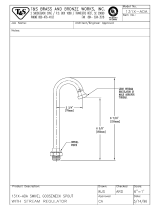
11. Check stream height from bubbler. Stream height is factory set at 45 50 PSI. If supply pressure varies greatly from this, remove
items 17 & 18 and adjust screw on regulator (item 14). Clockwise adjustment will raise stream height and CCW adjustment will lower
stream height. For best adjustment, stream height should be approximately 1-1/2 (38mm) above the bubbler guard. (See Fig. 15)
12. Connect refrigeration unit to electrical supply and check for proper operation. WARNING: Adequate space must be maintained behind
the refrigeration unit for air circulation.
13. Attach regulator holder (item 13) to grill (item 3) with hex nut (item 16). Hold grill and engage angle on top edge of grill with lower edge
of basin. Swing bottom of grill into place against the wall and securing grill mounting screws (provided).
FIG. 6
INSTALLATION INSTRUCTIONS
FOR THE
RC MODELS DRINKING FOUNTAIN
(refrigerated and non-refrigerated)

PAGE 4
RC8*C RC12*C AND 14762 & 14700 CUP DISPENSER
97095C (Rev. E - 10/99)
WATER SUPPLY CONNECTIONS RC8A/8AGF MODELS
WATER SUPPLY CONNECTIONS RC12A/12AGF MODELS
TO BUBBLER
CHILLER OUTLET
27
19
24
25
FIG. 7
FIG. 7A
FIG. 8 FIG. 8A
TO BUBBLER
CHILLER INLET
CHILLER OUTLET
27
19
24
25
TO BUBBLER
CHILLER INLET
CHILLER OUTLET
27
19
24
25
TO GLASSFILLER
TO GLASSFILLER
TO BUBBLER
CHILLER INLET
CHILLER OUTLET
27
19
24
25
CHILLER INLET
(Item 3, Page 7)
(Item 3, Page 7)

97095C (Rev. E - 10/99)PAGE 5
RC8*C RC12*C AND 14762 & 14700 CUP DISPENSER
INSTALLATION INSTRUCTIONS
FOR THE
RC CUP DISPENSER OPTION
MODELS: 14762
1. Open door of cup dispenser and remove waste bin.
2. Shim along the bottom and side of cup dispenser as reguired to
obtain a good alignment with previously installed drinking fountain.
Be sure to check for proper operation of access door before
securing unit in place. Securing can be done through slots
provided using screws or bolts (as required by wall construction).
3. Replace waste bin.
FIG. 9
FIG. 10
PLUMBING ROUGH-IN
CUP DISPENSER WITH GLASS FILLER
* NOTE If wall opening height has been adjusted
to meet local codes (see Step No. 1 of installa-
tion instructions), height dimensions must be
adjusted accordingly.

PAGE 6
RC8*C RC12*C AND 14762 & 14700 CUP DISPENSER
97095C (Rev. E - 10/99)
INSTALLATION INSTRUCTIONS
FOR THE
RC MODEL DRINKING FOUNTAIN
(with optional cup dispenser)
1. The 14700 Model Cup Dispenser with Glassfiller is designed to complement model RCA3 drinking fountains. The fountain should
already be installed before beginning installation, if not, refer to page 2 for your model. Remove louvered access panel from
fountain via the two screws at the bottom.
2. Check wall opening to see if provisions have been made to accept this cup dispenser. If they have not, refer to page 2 for rough-
in instructions. CAUTION: Wall construction must be framed to support fountain and cup dispenser (approximately 150 pounds).
3. See Parts List Illustration (page 7) for exact location of cup dispenser tailpiece. Decide which style of waste trap you intend to
use. For easier installation, we recommend the use of a swivel trap.
4. Orientate yourself to the configuration of the cup dispenser. Open front door and remove the spring loaded trash access panel.
To remove access panel, just loosen the four mounting screws and pull out the panel. Also remove the waste bin. Note location of
mounting slots in the wall box portion of the cup dispenser. The slots are for affixing wallbox to building construction.
5. Put cup dispenser in wall opening. Determine shimming required to obtain a good alignment with fountain. Open and close door
to ensure proper operation. CAUTION: Do not suspend cup dispenser via the mounting slots - be sure to shim along bottom edge
to bear the weight of the cup dispenser.
6. Secure cup dispenser in place. Use lag screws or bolts as required by wall construction.
7. Install glass filler supply tube assembly. (Figure 11). Put glass filler fitting through hole provided in back, put fibre washer on from
the front and screw on the hexagonal mounting nut. Note that the tubing itself is flex-tubing which will enable you to hand-form as
required for installation.
8. Install glass filler. First remove the blue handle, then screw the glass filler into the glass filler fitting. Reattach blue handle.
9. Turn off supply water to the RCA-3 drinking fountain. Disconnect supply tubing from fitting located at the push button valve
assembly. Remove elbow from valve assembly and install tube tee (provided). Reconnect supply water tubing (see parts list
illustration on page 7).
10. Connect glass filler supply tubing to tee.
11. Install tailpiece assembly (as shown in Figure 12). Connect waste trap (not provided).
12. Turn on supply water and operate push button valve and glass filler. Check entire system for leaks. Water flow from the glass
filler can be adjusted by turning the flow adjusting screw (see Figure 11). In order to adjust, it may be necessary to remove, and
then reinstall the glass filler, per step 8 above.
13. Replace the spring loaded trash access panel via the four mounting screws. Reinstall louvered grill on the RCA-3 fountain.
FIG. 11

97095C (Rev. E - 10/99)PAGE 7
RC8*C RC12*C AND 14762 & 14700 CUP DISPENSER
ITEMIZED PARTS LIST
ITEM NO.
PART NO. DESCRIPTION
101470051830
160807751640
161563108550
601565851550
411564208650
100115824740
100147140560
100352940560
110346220550
160270508640
160346008640
160346308640
161637308640
1
2
3
4
5
6
7
8
9
10
11
12
13
Disp - Cup w/GF Provisions
Assy - Valve Push Back
Tee - 3/8t x 3/8t x 1/4 NPT
GF Tube for 14700 Disp
Nut - Hex
Washer - Fibre
Gasket - Drain
Gasket - Slip Nut
Nut - Hex
Strainer - Plate
Tailpipe 1-1/4 x 4
Nut - Slip 1-1/2
Plug - Drain 1-1/2
FIG. 12
FIG. 13
10
BASIN
9
11
13
7
8
12
1
3
2
4,5,6
See Fig. 12
IMPORTANT: Fountain and glassfiller are rated
for a supply pressure of 90 PSI minimum. If
supply pressure exceeds this, a pressure
reducing regulator should be installed on the
supply line. Minimum supply pressure - 15 PSI.
PLUMBING ROUGH-IN
CUP DISPENSER WITH GLASS FILLER
* NOTE If wall opening height has been adjusted
to meet local codes (see Step No. 1 of installa-
tion instructions), height dimensions must be
adjusted accordingly.

PAGE 8
RC8*C RC12*C AND 14762 & 14700 CUP DISPENSER
97095C (Rev. E - 10/99)
FOR PARTS, CONTACT YOUR LOCAL DISTRIBUTOR OR CALL 1.800.323.0620
2222 CAMDEN COURT
OAK BROOK, IL 60523
630.574.3500
PRINTED IN U.S.A.
CORRECT STREAM HEIGHT
ITEMIZED PARTS LIST
ITEM NO. PART NO. DESCRIPTION
170857042830
27673C
732660951550
23040C
27671C
Reference
100147140560
160270508640
45400C
161637308640
45398C
51546C
45396C
100322740560
10080C
66347C
45440C
74050011
50986C
61313C
15005C
40169C
45427C
40048C
45419C
40089C
45422C
55996C
1110166
55884C
75588C
100147140560
62223C
62257C
62300C
70896C
1
2
3
4
5
6
7
8
9
10
11
12
13
14
15
16
17
18
19
20
21
22
23
24
25
26
27
Basin
Basin Aztec Gold
Mounting Frame
Grill
Grill Aztec Gold
Remote Chiller Assembly
Gasket
Strainer Plate Chrome
Strainer Plate Aztec Gold
Drain Plug - Chrome
Drain Plug Aztec Gold
Bubbler Chrome
Bubbler Aztec Gold
Gasket Bubbler (2-Reqd)
Nipple Bubbler
Tube Waste RC8
Waste Line/Precooler Assy-RC12
Sound Dampening Pad (NS)
Holder Regulator
Regulator
Retaining Nut
Hex Nut Chrome
Hex Nut Aztec Gold
Button Chrome
Button Aztec Gold
Cover Nut Chrome
Cover Nut Aztec Gold
Strainer
Screw - #8 x 3/4 Type AB
Elbow Drain
Nut - Slip Joint 1-1/4
Gasket - Drain
Tube - Cu. 3/8 x 4.75
Tube - Cu. Regulator In
Tube Assy - Bubbler 8880
Fitting - Elbow
TROUBLE SHOOTING AND MAINTENANCE
CAUTION: Cleaning of Aztec Gold Models requires special care. Outer
surfaces must be cleaned with a mild detergent or mixture of vinegar and
water only, rinsed and wiped dry. Abrasive and acidic cleaners may
eventually damage the Aztec Gold finish.
Orifice Assy: Mineral deposits on orifice can cause water flow to spurt or not
regulate. Mineral deposits may be removed from the orifice with a small
round file not over 1/8" diameter or small diameter wire. CAUTION: DO NOT
file or cut orifice material.
Stream Regulator: If orifice is clean, regulate flow as in instructions.
If replacement is necessary, see parts list for correct regulator part number.
Actuation of Quick Connect Water Fittings: Cooler is provided with lead-
free connectors which utilize an o-ring water seal. To remove tubing from the
fitting, relieve water pressure, push in on the gray collar while pulling on the
tubing.(see Fig.1) To insert tubing, push tube straight into fitting until it
reaches a positive stop, approximately 3/4".
FIG. 14
FIG. 15
18
BASIN
17
15
14
16 13
22
1
8,9,10
26
12
11
3
5,6,7,23
2
21
420
See Fig. 14
/