Page is loading ...


1
TracVision A5 Installation Guide – ADDENDUM
54-0208-01 Addendum to Rev. C
TracVision A5 Installation
Guide Addendum
ECO #6864
The following information applies to Revision C of the
TracVision A5 Installation Guide (KVH Part Number 54-0208-01).
The note on page 2.6 incorrectly states that a section of rubber,
neoprene, or foam should be attached to the base of the antenna
if there is less than 1" of space between the antenna and the roof.
KVH no longer recommends this action because it may cause the
center of the antenna to compress and possibly damage the
antenna’s internal parts.
The note on page 2.6 (Step 6) has been changed as shown below:
6. With the cushions installed in the brackets, the
bottom of the antenna should rest higher than 1"
above the vehicle’s roof. If the antenna’s base is
less than 1" from the roof, you will need to add a
spacer under each bracket to raise the antenna
higher off the crossbars.
If spacers are needed, follow the steps below to
install a spacer under each bracket:
a. Remove the #8-32 x
3
⁄8" screws and
washers securing the factory-installed
plastic spacer to the metal bracket.
b. Insert a second spacer from the
kitpack between the original spacer
(which holds the rubber cushions) and
the bracket. Secure both spacers to the
bracket using the #8-32 x 1" screws
supplied in the kitpack and the original
washers that you removed in Step a.
Bracket
New Spacer
Flat Washer
Lock Washer
#8-32 x 1" Screw
Factory-installed
Spacer
Adding a Second Spacer to the Bracket
If, after you have installed the spacers, there is less
than
1
⁄2" of space between the antenna and the roof,
KVH recommends that you either use the optional
roof mount kit or replace the roof rack with an
aftermarket model that offers greater clearance. If the
antenna is mounted too low, it may strike the roof
when the vehicle is in motion.

1
TracVision A5 Installation Guide – ADDENDUM
54-0208-01 Addendum to Rev. C
TracVision A5 Installation
Guide Addendum
ECO #6822
The following information applies to Revision C of the
TracVision A5 Installation Guide (KVH Part Number 54-0208-01).
The kitpack packaged with your TracVision A5 system does not
contain 16 tapered rubber cushions (24-0174), as described in the
Installation Guide. These cushions are unnecessary for a proper
installation. The 16 level rubber cushions (24-0173) supplied in
the kitpack should be used in all roof rack installations.
Step 5 of Section 2-1, “Mounting the Antenna to the Vehicle’s Roof,”
has been changed to remove references to the tapered cushions:
5. Each bracket and retaining block (which you will
attach to the bracket later) contains several pairs of
pegs. These pegs allow you to place the four
rubber cushions in different positions to best fit
the vehicle’s particular style of crossbars.
Try out the various cushion positions until you
find the best fit for your installation.
The more surface area of the cushions pressing against
the top and bottom of the crossbar, the better the fit.
Level Cushion - Supplied
Tapered Cushion - Not Supplied
Bracket
Roof Rack Crossbar
Rubber Cushions
Rubber Cushions
Retaining Block
Pegs
Positioning Rubber Cushions for Best Fit

1
TracVision A5 Installation Guide – ADDENDUM
54-0208-01 Addendum to Rev. C
TracVision A5 Installation
Guide Addendum
ECO #6705
The following information applies to Revision C of the
TracVision A5 Installation Guide (KVH Part Number 54-0208-01).
When you start up the TracVision antenna, do not move the
vehicle for 20 seconds. This allows the antenna gyros to initialize
properly, ensuring optimum satellite tracking performance.
4-3 Testing the System
Now all you need to do is turn the system on and ensure
everything works properly. Follow the steps below to turn on the
TracVision A5 system and verify proper operation.
1. Ensure that the antenna has a clear view of the
satellite. The antenna requires an unobstructed
view of the southern sky to receive satellite TV
signals. Trees, buildings, highway overpasses, etc.,
can block satellite signals. Heavy rain or snow
may also interrupt satellite signals. For complete
details about satellite reception requirements, refer
to Section 1.3, “Receiving Satellite TV Signals,” in the
TracVision A5 User’s Guide.
2. Apply vehicle power and turn on the vehicle’s
entertainment system.
3. Turn on the TracVision A5 receiver’s front panel
power switch. The switch’s light illuminates and
the receiver beeps twice.
4. Wait 30 seconds. The antenna should then power
off and the receiver should beep once.
Since the TracVision antenna requires an unobstructed
view of the southern sky to receive satellite signals, the
system will not work when the vehicle is in a garage.
Receiver Front Panel Power Switch
Power Switch

2
5. Press the remote control’s SAT button. The button
should blink red. If it doesn’t, check the remote
control’s batteries.
6. Now press the POWER button. The receiver beeps
twice to indicate that power is again applied to the
antenna.
7. Do not move the vehicle for 20 seconds. This
allows the antenna gyros to initialize properly.
8. Verify that the following appears on the TV(s):
The TracVision antenna searches for and locks
onto the satellite. The receiver then starts
downloading the program guide and the
following message appears:
This process may take up to 60 seconds. Once the
program guide has loaded, a DIRECTV
programming channel appears. Only the DIRECTV
preview channels (such as channels 100 and 201) are
viewable until the user activates the receiver.
Installation
If your satellite dish is ready for DIRECTV
®
service, please wait until your
Advanced Program Guide
™
is prepared.
Searching for satellite signal...
Installation
If your satellite dish is ready for DIRECTV
®
service, please wait until your
Advanced Program Guide
™
is prepared.
Acquiring guide data...
CHVOL
PWR
DVD VCR AUX TV SAT
GUIDE
MENU
INFO CLEAR
TURBO
FAV
SELECT
MUTE
CH
PREV
P
A
G
E
O
N
E
L
I
N
E
G
U
I
D
E

1
TracVision A5 Installation Guide – ADDENDUM
54-0208-01 Addendum to Rev. C
TracVision A5 Installation
Guide Addendum
ECO #6670
The following information applies to Revision C of the
TracVision A5 Installation Guide (KVH Part Number 54-0208-01).
Recording the Antenna Serial Number
Before installing the system, peel off the extra antenna serial
number label (taped to the antenna) and affix it in the
appropriate box on the activation information card that is
attached to the receiver. In addition, enter the antenna serial
number in the appropriate box on the first page of the TracVision
A5 User’s Guide. The user will need this number to activate the
receiver, and the receiver must be activated in order to watch
satellite TV via the TracVision A5 system.

1
TracVision A5 Installation Guide – ADDENDUM
54-0208-01 Addendum to Rev. C
TracVision A5 Installation
Guide Addendum
ECO #6669
The following information applies to Revision C of the
TracVision A5 Installation Guide (KVH Part Number 54-0208-01).
Shipping Restraints
To better prevent shipping damage, wire rope is now used
instead of plastic tie-wraps to secure the antenna mechanism in
place. To remove these restraints, you will need to use heavy-
duty wire cutters to snip the wire.
1
2
3
4
6
5
Do not remove the restraints until you have attached the
four mounting brackets to the antenna’s base and are
ready to place the antenna onto the vehicle. See
Section 2-1, “Mounting the Antenna to the Vehicle’s Roof.”
Shipping Restraint Locations

1
TracVision A5 Installation Guide – ADDENDUM
54-0208-01 Addendum to Rev. C
TracVision A5 Installation
Guide Addendum
ECO #6516
The following information applies to Revision C of the
TracVision A5 Installation Guide (KVH Part Number 54-0208-01).
The RF-to-IR converter described in the manual has been
replaced with a new RF converter. This new component receives
RF signals from the remote control and converts them directly to
digital signals, which the receiver can understand.
The following pages show the resulting changes to the TracVision A5
Installation Guide.
New RF Converter

2
1-2 System Overview
A complete satellite TV system includes the TracVision A5
antenna and receiver connected to the vehicle’s audio/video
entertainment system. The remote control and RF converter
allow the user to operate the system from anywhere in the
vehicle.
(RF = Radio Frequency)
RF Converter
The RF converter receives radio frequency commands from the
remote control, converts them to digital signals, and sends them
to the receiver for processing.
Vehicle
Audio/Video System
TracVision A5 Antenna
Purchased Separately
Receiver
Remote Control
CH
VOL
DVD
VCR AUX TV
SAT
HRMC-9
GUIDE
MENU
INFO
CLEAR
TURBO
FAV
SELECT
MUTE
CH
P
R
E
V
PR
O
G
S
E
A
R
C
H
A
U
D
IO
V
ID
EO
1
2
3
4
5
6
7
8
9
0
IN
P
U
T
REW
PLAY
FF
REC
STOP
PAUSE
P
A
G
E
O
N
E
L
I
N
E
G
U
I
D
E
P
W
R
D
IR
E
C
T
O
R
RF Converter
Vehicle Power
(10-16 VDC)
TracVision A5 System Diagram (Typical Installation)

1-3 Materials Provided
The table of provided components has been updated to list the
new RF converter.
Component KVH Part #
Packaged in antenna box:
Antenna unit 02-1289-01
Packaged in receiver box:
Receiver 02-1287-01
RF converter 02-1344
Remote control 19-0335
TracVision A5 User’s Guide 54-0208
TracVision A5 Installation Guide 54-0208-01
1-4 Planning the Installation
Kitpack Contents
The RF-to-IR converter cable (part # 32-0773) has been removed from
the kitpack. It is no longer needed, since the new RF converter comes
with an attached cable.
3
TracVision A5 Installation Guide – ADDENDUM
54-0208-01 Addendum to Rev. C

3-1 Wiring the Receiver
The receiver rear panel has been modified to accept the new RF
converter cable. The diagram below shows the new receiver
wiring.
Connecting the RF Converter Cable
To connect the RF converter cable, follow the steps below.
1. Connect the RF converter cable to the “RF Remote
Input” jack on the receiver’s rear panel.
2. Place the RF converter at least three feet away
from the receiver’s location.
Connecting an Existing IR Input (Optional)
The optional vehicle IR adapter cable is no longer available. Use
the new RF converter in all installations.
4
TracVision A5 Wiring Diagram
Antenna
For detailed system wiring
instructions, refer to the
TracVision A5 Installation Guide
.
RF Converter
Receiver
Vehicle Roof
CAUTION
KVH
®
is a registered trademark of KVH Industries, Inc. HUGHES
™
is a trademark of Hughes Electronics Corporation.
This device complies with Part 15J of the FCC rules. Operation is subject to the following two conditions:
(1) This device must not cause harmful interference, and (2) This device must accept any interference
received, including interference that may cause undesired operation.
Product Warranty void if outer casing removed
.
VEHICLE POWER
(10-16 VDC)
VHF
ANTENNA IN
S-VIDEO
TO KVH
ANTENNA
TO VIDEO
Tr uSurround, SRS and symbol are trademarks of SRS Labs, Inc.
SATELLITE IN
AUDIO R
AUDIO L
VIDEO
Service/
Maintenance
Only
DC Power
Ground
To Vehicle
Audio
To Vehicle Video
(Option 1)
To Vehicle Video
(Option 1)
To Vehicle Video
(Option 3)
To Vehicle Video
(Option 2)
To VHF Antenna
(Optional)
Vehicle Power
(10-16 VDC)
Fuse
RF REMOTE
INPUT
OUT TO TV
COMPOSITE VIDEO
TO IRD
SATELLITE IN
DIAGNOSTIC PORT 1
DIAGNOSTIC PORT 2
The RF converter must be placed at least three feet away
from the receiver. Placing the RF converter closer to the
receiver may result in interference, causing the remote
control to operate intermittently or not at all.

1
TracVision A5 Installation Guide – ADDENDUM
54-0208-01 Addendum to Rev. C
TracVision A5 Installation
Guide Addendum
ECO #6423
The following information applies to Revision C of the
TracVision A5 Installation Guide (KVH Part Number 54-0208-01).
Rubber Cushions All Black
All of the rubber cushions provided with the TracVision A5 are
black in color. The level rubber cushions (described in step 5 of
Section 2-1, “Mounting the Antenna to the Vehicle’s Roof,” on
page 2.5) are black, not gray, in color.
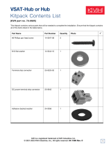
New Antenna Mounting Hardware
The
1
⁄4"-20 x 2
1
⁄2" tamper-resistant screws provided in the
TracVision A5 kitpack differ from those described in the manual.
They have a Snake Eyes
®
head instead of a TORX
®
head. The
kitpack also includes a Snake Eyes bit for tightening these screws.
New part numbers are noted below.
Part Part # Qty.
1
⁄4"-20 x 2
1
⁄2" Snake Eyes screws 14-0373-40 8
Tamper-proof Snake Eyes bit 14-0379 1
The Snake Eyes screws are only necessary if you need to install a
spacer underneath each antenna mounting bracket, as described
in step 6 of Section 2-1, “Mounting the Antenna to the Vehicle’s
Roof,” on page 2.6. Steps 8 and 9 of Section 2-1 are superseded by
the information on the following pages.
Snake Eyes
Screw Head

2
8. Insert the appropriate tamper-resistant flat-head
screws into each bracket’s swivel nuts:
If you DID NOT install spacers in Step 6:
Insert
1
⁄4"-20 x 2" TORX screws into the bracket’s
swivel nuts.
If you DID install spacers in Step 6:
Insert
1
⁄4"-20 x 2
1
⁄2" Snake Eyes screws into the
bracket’s swivel nuts.
Be sure to use the tamper-resistant hardware provided in
the kitpack.
Bracket
Bracket Screws
(Tamper-proof)
Cover
Roof Rack Crossbar
Retaining Block
Rubber Cushions
Swivel Nuts
Swivel Nuts
Rubber Cushions
Flat Washers
Lock Nuts
Securing the Brackets to the Crossbars

9. At each bracket, position a retaining block
underneath the crossbar and insert two swivel
nuts,
1
⁄4" flat washers, and lock nuts into the captive
holes from below. While holding this hardware in
place, screw the bracket’s screws into the retaining
block’s swivel nuts, washers, and lock nuts using a
1
⁄4" driver and the supplied T27 TORX bit or Snake
Eyes bit, as required. After securing all four
brackets to the crossbar, verify that all cushions are
pressed firmly against the crossbar, providing a
solid grip. Also check to make sure that all eight
screws have engaged the nylon inserts in the lock
nuts.
3
TracVision A5 Installation Guide – ADDENDUM
54-0208-01 Addendum to Rev. C
Securing the Tamper-proof Screws
Tamper-proof
Screws
Retaining Block
Retaining Block
Swivel Nut
Flat Washer
Lock Nut

TracVision A5
Installation Guide
The TracVision A5 is a state-of-the-art, actively
stabilized antenna system that delivers live satellite
TV to a vehicle, even while the vehicle is moving.
This manual provides detailed instructions on the
proper installation of the TracVision A5 system.
Complete instructions on how to use the system are
provided in the TracVision A5 User’s Guide.
Welcome Page
This product must NOT be connected to
any active monitor that is visible to the
vehicle’s driver while the vehicle is in
motion.This product is intended for rear-
seat entertainment only.
KVH Part # 54-0208-01 Rev . C
© 2003, KVH Industries, Inc.
Patents Pending
Click here to go to our state-of-the-art Customer
Support web page...the fastest and easiest way to
get all of your questions answered!

Trademarks
KVH
®
and TracVision
®
are registered trademarks of KVH Industries, Inc.
DIRECTV
®
and the Cyclone Design logo, DIRECTV INTERACTIVE, TOTAL
CHOICE, DIRECTV HOME SERVICES, and DIRECT TICKET are
trademarks of DIRECTV, Inc., a unit of Hughes Electronics Corp. FREEVIEW
is a registered trademark of Hughes Electronics Corporation. All trademarks,
marks, names, or product names referenced in this publication are the
property of their respective owners, and KVH neither endorses nor otherwise
sponsors any such products or services referred to herein.
Dolby Laboratories Information – Manufactured under license from Dolby
Laboratories.“Dolby,” “Pro Logic,” and the double-D symbol are trademarks of
Dolby Laboratories.
Macrovision
®
Information – Macrovision is a registered trademark of
Macrovision Corporation.This device incorporates an anticopy process
technology that is protected by U.S. patents 4,631,603; 4,577,216; 4,819,098;
and other intellectual property rights.The anticopy process is licensed for
noncommercial, home use only. Reverse engineering or disassembly is
prohibited.
StarSight
®
Information – StarSight features licensed under one or more of the
following patents: 4,706,121; 5,151,789; 5,353,121; 5,353,277; 5,479,266;
5,479,268; and 5,532,754. Use rights reserved.
Tr uSurround
™
Information – TruSurround and the symbol are
trademarks of SRS Labs, Inc.TruSurround technology is incorporated under
license from SRS Labs, Inc.
WINK
®
Information – WINK and the symbol are registered trademarks of
WINK Communications, Inc.
ENERGYSTAR
®
Information – ENERGYSTAR and the ENERGYSTAR
certification mark are registered US marks.
TORX
®
is a registered trademark of Camcar/Textron, Inc.
Snap-N-Seal
®
is a registered trademark of Thomas & Betts Corporation.
Hummer
®
is a registered trademark of GM Corporation.
Software contained in the TracVision A5 receiver and referenced in this
manual is copyright ©1995-2003 by Hughes Network Systems, Inc., a wholly
owned subsidiary of Hughes Electronics Corporation. Some features are
patent pending.WatchWizard, PreSelect, TurboTune, and OneLine Guide are
trademarks of Hughes Network Systems.“NFL,” the NFL Shield, and “NFL
SUNDAY TICKET” are registered trademarks of the National Football League
and its affiliates.“NHL,” the NHL Shield, and “NHL CENTER ICE” are
registered trademarks of the National Hockey League.“MLB,” “MLB EXTRA
INNINGS,” “Major League Baseball,” and the Major League Baseball
silhouetted batter logo are service marks of Major League Baseball
Properties, Inc. Major League Baseball trademarks and copyright are used
with permission of Major League Baseball Properties, Inc. All other
trademarks and service marks are the property of their respective owners.
Disclaimer
Every effort has been made to ensure the correctness and completeness of
the material in this document. No company shall be liable for errors
contained herein.The information in this document is subject to change
without notice. No warranty of any kind is made with regard to this material,
including, but not limited to, the implied warranties of merchantability and
fitness for a particular purpose.
Note on recording programming
Most television programs and films are copyrighted.This means that
someone has legal rights governing the reproduction and distribution of this
material. In certain circumstances, copyright law may apply to private taping
of copyrighted materials. In most cases, it is permissible to record for your
personal use, as long as you do not sell the material.You must act
responsibly in this area–check into the matter if you are unsure.
Some pay-per-view programs may be licensed from producers as “view-only”
programs.These are copyrighted programs, and may not be copied or
reproduced for any purpose without the express written permission of the
copyright owner.
54-0208-01
ii
TracVision A5 Installation Guide

Important Safety Instructions - Please
Read Carefully
For your safety and protection, read this entire
Installation Guide before you install the TracVision
system. In particular, read this safety section carefully.
Heed Cautions – Be sure to follow all cautions on the
product and in the installation instructions. Cautions
are indicated by a or icon.
Follow Instructions – Be sure to follow all installation
instructions as detailed in this manual.
The following caution appears on the back of the
receiver:
Do not open the receiver’s cover. Opening or
removing the cover may expose you to dangerous
voltage.
To reduce the risk of fire or
electrical shock, do NOT expose the
receiver to rain or moisture and do
NOT insert any objects into the
receiver’s ventilation openings.
54-0208-01
iii
Important Safety Instructions
Avoid Driver Distraction
It is dangerous to watch television
or operate the remote control
while you are driving a vehicle.
The TracVision A5 is designed
specifically to provide entertainment to vehicle
passengers and should never be connected to
active video screens visible to the vehicle driver
while the vehicle is in motion. Failure by the
driver of a vehicle equipped with a
TracVision A5 to pay full attention to traffic and
road conditions could result in an accident or
collision with personal injury or death resulting.
WARNING!
CAUTION
CAUTION

Federal Communications Commission (FCC)
Regulatory Information
Declaration of Conformity – Standards to which Conformity is declared:
FCC Part 15
This device complies with Part 15 of the FCC Rules. Operation is subject
to the following two conditions: (1) this device may not cause harmful
interference, and (2) this device must accept any interference received,
including interference that may cause undesired operation.
Responsible Party’s Name: KVH Industries, Inc.
Address: 50 Enterprise Center, Middletown, RI 02842
Telephone: 1-401-847-3327
Trade Name: KVH
Type of Equipment: Satellite Receiver
Model Number: TracVision A5
Federal Communications Commission (FCC) –This equipment complies
with Part 15 of the FCC rules.
Part 15 Compliance – This equipment has been tested and found to comply
with the limits for a Class B digital device, pursuant to Part 15 of the FCC
rules.These limits are designed to provide reasonable protection against
harmful interference in a vehicle installation.This equipment generates, uses,
and can radiate radio frequency energy and, if not installed and used in
accordance with the instructions, may cause harmful interference to radio
communications.
However there is no guarantee that interference will not occur in a particular
installation. If this equipment does cause harmful interference to radio or
television reception, which can be determined by removing and applying
power to the equipment, the user is encouraged to try to correct the
interference by one or more of the following measures:
• Increase the separation between the equipment and the
receiver.
• Connect the equipment on a circuit different from that to which the
receiver is connected.
• Consult the dealer or an experienced auto electronics technician for help.
The user may find the following booklet, prepared by the Federal
Communications Commission, helpful: “How to Identify and Resolve Radio
and TV Interference Problems.” This booklet is available from the U.S.
Government Printing Office, Washington, DC.
To meet FCC requirements, only components certified to comply with Class
B limits may be attached to this device. Operation with noncertified
peripherals is likely to result in interference to radio and TV reception.
To meet FCC requirements, shielded cables are required to connect the
device to another Class B certified device.
54-0208-01
iv
TracVision A5 Installation Guide

Technical Support
If you need technical assistance when installing the
TracVision A5, please call KVH Technical Support:
Phone: (401) 847-3327
E-mail: [email protected]
Internet: www.kvh.com/help
54-0208-01
v
Technical Support
Send Us Your Comments About This Manual
If you have any comments regarding this manual,
please e-mail them to [email protected]. Your
feedback is greatly appreciated!

Table of Contents
1 Getting Started . . . . . . . . . . . . . . . . .1.1
1-1 Using this Manual . . . . . . . . . . . . . . .1.3
1-2 System Overview . . . . . . . . . . . . . . . .1.4
1-3 Materials Provided . . . . . . . . . . . . . . .1.6
1-4 Planning the Installation . . . . . . . . . . .1.6
2 Installing the Antenna . . . . . . . . . . . .2.1
2-1 Mounting the Antenna to the
Vehicle’s Roof . . . . . . . . . . . . . . . . . .2.3
2-2 Connecting the Antenna Cable . . . . .2.9
3 Installing the Receiver . . . . . . . . . . . .3.1
3-1 Wiring the Receiver . . . . . . . . . . . . . .3.3
3-2 Mounting the Receiver . . . . . . . . . . .3.12
4 Completing the Installation . . . . . . . . .4.1
4-1 Installing the Remote Control
Batteries . . . . . . . . . . . . . . . . . . . . . .4.3
4-2 Post-installation Checklist . . . . . . . . .4.4
4-3 Testing the System . . . . . . . . . . . . . .4.6
4-4 Activating the Receiver . . . . . . . . . . .4.7
4-5 Programming the Remote Control
to Operate Other Components
(Optional) . . . . . . . . . . . . . . . . . . . . .4.8
Appendices . . . . . . . . . . . . . . . . . . . . . .A.1
A System Specifications . . . . . . . . . . . .A.3
B Manufacturer Device Codes . . . . . . . .A.5
Warranty . . . . . . . . . . . . . . . . . . . . . . . . .A.17
54-0208-01
vii
Table of Contents
/