
ENGLISH
Copyright © 2016 EATON
All rights reserved.
5SC 1 - 3 KVA US_EN
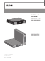
5SC 1000i Rack2U
5SC 1500i Rack2U
5SC 2200i RT2U
5SC 3000i RT2U
Installation and
user manual

Page 2
5SC 1 - 3 KVA US_EN

Page 3
5SC 1 - 3 KVA US_EN
ENGLISH
Certification Standards
Uninterruptible power systems (UPS) directives:
• IEC 62040-1: General and safety requirements for UPS
• IEC 62040-2: Electromagnetic compatibility (EMC) requirements
• IEC 62040-3: Method of specifying the performance and test requirements
• IEC 62040-4: Environmental aspects - Requirements and reporting
CE mark
CE compliance contact: Eaton I.F. – 110 rue Blaise Pascal – 38330 Montbonnot Saint Martin - France
The EC Declaration of Conformity is available upon request for products with a CE mark.
For copies of the EC Declaration of Conformity, contact Eaton Power Quality or check Eaton website:
www.powerquality.eaton.com
Class B emission level CISPR 22 (EN 55022)
Harmonics emission: IEC 61000-3-2
Flickers emission: IEC 61000-3-3
Special Symbols
The following are examples of symbols used on the UPS or accessories to alert you to important
information:
RISK OF ELECTRIC SHOCK - Observe the warning associated with the risk of electric shock symbol.
Important instructions that must always be followed.
Do not discard the UPS or the UPS batteries in the trash.
This product contains sealed lead acid batteries and must be disposed as it's explain in this manual.
For more information, contact your local recycling/reuse or hazardous waste center.
This symbol indicates that you should not discard waste electrical or electronic equipment (WEEE) in the
trash. For proper disposal, contact your local recycling/reuse or hazardous waste center.
Information, advice, help.

Page 4
5SC 1 - 3 KVA US_EN
Safety of Persons
• The system has its own power source (the battery). Consequently, the power outlets may be energized
even if the systems is disconnected from the AC power source.
• Dangerous voltage levels are present within the system. It should be opened exclusively by qualified
service personnel.
• The system must be connected to an earthed outlet.
• The battery supplied with the system contains small amounts of toxic materials.
To avoid accidents, the directives listed below must be observed:
- servicing of batteries should be performed or supervised by personnel knowledgeable about batteries
and the required precautions.
- when replacing batteries, replace with the same type and number of batteries or battery packs.
- do not dispose of batteries in a fire. The batteries may explode.
- batteries constitute a danger (electrical shock, burns). The short-circuit current may be very high.
Precautions must be taken for all handling:
• Wear rubber gloves and boots.
• Do not lay tools or metal parts on top of batteries.
• Disconnect charging source prior to connecting or disconnecting battery terminals.
Product Safety
• The UPS connection instructions and operation described in the manual must be followed in the indicated
order.
• A protection circuit breaker must be installed upstream and be easily accessible.
The system can be disconnected from the AC power source by opening this circuit breaker or unplugging
the input cable.
• Check that the indications on the rating plate correspond to your AC powered system and to the actual
electrical consumption of all the equipment to be connected to the system.
• For PLUGGABLE EQUIPMENT, the socket-outlet shall be installed near the equipment and shall be easily
accessible.
• Never install the system near liquids or in an excessively damp environment.
• Never let a foreign body penetrate inside the system.
• Never block the ventilation grates of the system.
• Never expose the system to direct sunlight or source of heat.
• If the system must be stored prior to installation, storage must be in a dry place.
• The admissible storage temperature range is -15 to +50 ºC / 5 to 122 ºF.
• The system is not for use in a computer room.
Special Precautions
• All handling operations will require at least two people (unpacking, installation in rack system).
• Before and after the installation, if the UPS remains de-energized for a long period, the UPS must be
energized for a period of 24 hours, at least once every 6 months (for a normal storage temperature less
than 25 °C / 77 °F). This charges the battery, thus avoiding possible irreversible damage.
• During the replacement of the Battery Module, it is imperative to use the same type and number of element
as the original Battery Module provided with the UPS to maintain an identical level of performance and
safety. In case of doubt, don’t hesitate to contact your EATON representative.

Page 5
5SC 1 - 3 KVA US_EN
ENGLISH
Contents
1. Introduction ....................................................................................... 6
1.1 Environmental protection ................................................................................................... 6
2. Presentation ...................................................................................... 7
2.1 Standard installations ........................................................................................................7
2.2 Rear panels ........................................................................................................................8
2.3 Control panel .....................................................................................................................9
2.4 LCD description .................................................................................................................9
2.5 UPS setting through the LCD ............................................................................................9
3. Installation ...................................................................................... 10
3.1 Unpacking and contents check ........................................................................................ 10
3.2 Installation of tower models ............................................................................................ 11
3.3 Installation of rack models ............................................................................................... 11
3.4 Wall mounting of rack models ......................................................................................... 13
3.5 Communication ports ...................................................................................................... 14
3.6 UPS remote control functions ......................................................................................... 15
4. Operation ......................................................................................... 16
4.1 Start-up and Normal operation......................................................................................... 16
4.2 Starting the UPS on Battery ............................................................................................ 16
4.3 UPS Shutdown ................................................................................................................16
4.4 Operation on Battery Power ............................................................................................16
4.5 Return of AC Input Power ................................................................................................ 16
5. Maintenance.................................................................................... 17
5.1 Troubleshooting ................................................................................................................ 17
5.2 Battery-module replacement ...........................................................................................18
6. Appendices ...................................................................................... 19
6.1 Technical specications ....................................................................................................19
6.2 Glossary ...........................................................................................................................20

Page 6
5SC 1 - 3 KVA US_EN
1. Introduction
Thank you for selecting an EATON product to protect your electrical equipment.
The 5SC range has been designed with the utmost care.
We recommend that you take the time to read this manual to take full advantage of the many features of your
UPS (Uninterruptible Power System).
Before installing 5SC, please read the booklet presenting the safety instructions. Then follow the indications
in this manual.
To discover the entire range of EATON products and the options available for the 5SC range, we invite you to
visit our web site at www.eaton.com/powerquality or contact your EATON representative.
1.1 Environmental protection
EATON has implemented an environmental-protection policy.
Products are developed according to an eco-design approach.
Substances
This product does not contain CFCs, HCFCs or asbestos.
Packing
To improve waste treatment and facilitate recycling, separate the various packing components.
• The cardboard we use comprises over 50 % of recycled cardboard.
• Sacks and bags are made of polyethylene.
• Packing materials are recyclable and bear the appropriate identification symbol
01
PET
Materials Abbreviations
Nu
m
ber in
01
PET
the symbols
Polyethylene terephthalat PET 01
High-density polyethylene HDPE 02
Polyvinyl chloride PVC 03
Low-density polyethylene LDPE 04
Polypropylene PP 05
Polystyrene PS 06
Follow all local regulations for the disposal of packing materials.
End of life
EATON will process products at the end of their service life in compliance with local regulations.
EATON works with companies in charge of collecting and eliminating our products at the end of their service
life.
Product
The product is made up of recyclable materials.
Dismantling and destruction must take place in compliance with all local regulations concerning waste.
At the end of its service life, the product must be transported to a processing centre for electrical and electronic
waste.
Battery
The product contains lead-acid batteries that must be processed according to applicable local regulations
concerning batteries.
The battery may be removed to comply with regulations and in view of correct disposal.

Page 7
5SC 1 - 3 KVA US_EN
ENGLISH
2. Presentation
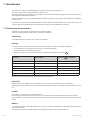
2.1 Standard installations
Rack installation
D
H
W
Tower installation
(Only for 5SC 2200i RT2U and 5SC 3000i RT2U models)
D
H
W
Description Weights (kg/lb) Dimensions (mm/inch)
D x W x H
5SC 1000i Rack2U 15.0 / 33.0 405*440*86.2 / 15.9*17.3*3.4
5SC 1500i Rack2U 17.8 / 39.2 405*440*86.2 / 15.9*17.3*3.4
5SC 2200i RT2U 26.5 / 58.3 522*440*86.2 / 20.6*17.3*3.4
5SC 3000i RT2U 35.3 / 77.7 647*440*86.2 / 25.5*17.3*3.4

Page 8
5SC 1 - 3 KVA US_EN
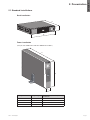
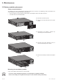
2.2 Rear panels
5SC 1000i Rack2U and 5SC 1500i Rack2U
4 5 6
1 2 3
5SC 2200i RT2U
2 6 3 1
54
5SC 3000i RT2U
2 6 3 1
54
(1) Socket for connection to AC power source
(2) Slot for optional communication card
(3) Outlets for connection of equipment
(4) RS232 communication port
(5) USB communication port
(6) Connector for ROO (Remote ON/OFF) or RPO (Remote Power Off) control
2. Presentation

Page 9
5SC 1 - 3 KVA US_EN
ENGLISH
2. Presentation
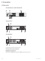
2.3 Control panel
The UPS has a three-button LCD. It provides useful information about the UPS itself, load status, events,
measurements and settings.
AVR
%
Min
Hz
kVA
kW
7
8
9
7
ON/OFF button
8
Scroll down
9
Mute alarm
2.4 LCD description
1211
1310
1514
1816
17
10
UPS ON
11
AVR mode
12
Battery mode
13
Internal fault
14
Output load level
15
Battery level
16
Input measurements
17
Output measurements
18
Measuring unit
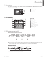
2.5 UPS setting through the LCD
Release scroll down button to select menu
5s 2s
2s
2s
Output voltage Alarm
Sensitivity
(1)
(1) In low sensitivity mode (Lo) UPS will tolerate more uctuations in power and will go on battery power less often.
If the connected load is sensitive to power disturbances, keep the sensitivity as Standard (Std).
Example of setting
10s 5s 5s
Save the new value
• LCD will shut off if no activity for 3 minutes.

Page 10
5SC 1 - 3 KVA US_EN
3. Installation
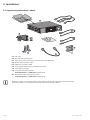
3.1 Unpacking and contents check
19
21
22
24
23
25
27
26
20
(19) 5SC UPS
(20) Rail and wall mounting kits
(21) Quick start, safety instructions and environmental document
(22) RS232 communication cable
(23) USB communication cable
(24) 2 connection cables for the protected equipment
(25) Cable locking systems
(26) 2 supports for tower position
(5SC 2200i RT2U and 3000i RT2U models only)
(27) Connection cable to AC-power source
(5SC 2200i RT2U and 3000i RT2U models only)
Packing materials must be disposed of in compliance with all local regulations concerning waste.
Recycling symbols are printed on the packing materials to facilitate sorting.

Page 11
5SC 1 - 3 KVA US_EN
ENGLISH
3. Installation
3.2 Installation of tower models
Only for 5SC 2200i RT2U and 5SC 3000i RT2U models
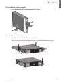
3.3 Installation of rack models
5SC 1000i Rack2U and 5SC 1500i Rack2U models
Follow steps 28 to 30 for model mounting on the rails.
Use provided screws on step 28 of installation. Using a longer screw could present a safety risk.
28
30
30
28
29

Page 12
5SC 1 - 3 KVA US_EN
3. Installation
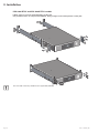
5SC 2200i RT2U and 5SC 3000i RT2U models
Follow steps 31 to 33 for model mounting on the rails.
Use provided screws on step 33 of installation. Using a longer screw could present a safety risk.
33
33
31
32
31
34
34
The rails and necessary hardware are supplied by EATON

Page 13
5SC 1 - 3 KVA US_EN
ENGLISH
3. Installation
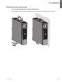
3.4 Wall mounting of rack models
Only for 5SC 1000i Rack2U and 5SC 1500i Rack2U
Use provided screws on step 35 of installation. Using a longer screw could present a safety risk.
35
35
36
36

Page 14
5SC 1 - 3 KVA US_EN
3. Installation
3.5 Communication ports
Connection of RS232 or USB communication port
The RS232 and USB communication ports cannot operate simultaneously.
4
23
22
5
Installation of the communication cards (optional)
2
Characteristics of the contact RS232 communication port
When a signal is activated, the contact is closed between the common (pin 2) and the pin for the corresponding
signal.
Contact characteristics (optocoupler)
• Voltage: 48 V DC max
• Current: 25 mA max
• Power: 1.2 W
1. Connect the RS232 (22) or USB
(23) communication cable to
the serial or USB port on the
computer equipment.
2. Connect the other end of the
communication cable (23) or
(22) to the USB (5) or RJ45
(4) communication port on the
UPS.
The UPS can now communicate
with EATON power management
software.
It is not necessary to shut down
the UPS before installing a
communication card.
1. Remove the slot cover (2)
secured by screws.
2. Insert the communication card
in the slot.
3. Secure the card cover with the
2 screws.
• Pins 1, 3, 4, 5, 6, 10: not used
• Pin 2: common (user)
• Pin 7: low battery
• Pin 8: operation on battery
power
• Pin 9: UPS ON, equipment
supplied
n.o.: normally open contact

Page 15
5SC 1 - 3 KVA US_EN
ENGLISH
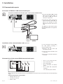
3.6 UPS remote control functions
The 5SC offers a choice between two remote control functions.
• RPO: Remote Power Off allow a remote contact to be used to disconnect all the equipment connected to
the UPS. Restarting the UPS requires manual intervention.
• ROO: Remote ON/OFF allows remote action of button
to shut down the UPS.
These functions are obtained by opening a contact connected between the appropriate pins of connector (6)
on the rear panel of the UPS (see figures below).
6
Remote control connection and test
1. Check that the UPS is OFF and disconnected from the AC input source.
2. Remove connector (6) after unscrewing the screws.
3. Connect a normally closed volt-free contact (60 V DC / 30 V AC max., 20 mA max., 0.75 mm
2
cable cross-
section) between the two pins of connector (6) (see diagram).
6
Contact open: UPS shutdown
Contact closed: UPS start-up (UPS connected to AC power and AC power is available)
Note: The local ON/OFF control using button
overrides the remote-control function.
6
Contact open: UPS shutdown, LED goes ON.
To return to normal operation, deactivate the remote external contact and restart the UPS
by pressing button
.
4. Plug connector (6) into the back of the UPS.
5. Connect and restart the UPS following the previously described procedures.
6. Activate the external remote shutdown contact to test the function.
Warning. This connector must only be connected to SELV (Safety Extra-Low Voltage) circuits.
3. Installation

Page 16
5SC 1 - 3 KVA US_EN
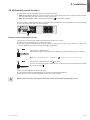
4. Operation
4.1 Start-up and Normal operation
To start the UPS:
1. Verify that the UPS power cord is plugged in.
2. Press the
button on the UPS front panel for at least 2 seconds.
3. Check the UPS front panel display for active alarms.
If the
indicator is on, do not proceed until all alarms are cleared.
Correct the alarms and restart if necessary.
4. Verify that the
indicator illuminates solid, indicating that the UPS is operating normally and any loads
are powered and protected.
4.2 Starting the UPS on Battery
Before using this feature, the UPS must have been powered by utility power with output enabled at
least once.
To start the UPS on battery:
1. Press the
button on the UPS front panel until the UPS front panel display illuminates.
The UPS cycles through Standby mode to Battery mode. The
indicator illuminates solid.
The UPS supplies power to your equipment.
2. Check the UPS front panel display for active alarms. Resolve any active alarms before continuing.
See "Troubleshooting" in section 5.1.
4.3 UPS Shutdown
To shut down the UPS:
Press the
button on the front panel for three seconds.
The UPS starts to beep. The UPS then transfers to Standby mode, and the
indicator turns off.
4.4 Operation on Battery Power
Transfer to battery power
• The connected devices continue to be supplied by the UPS when AC input power is no longer available.
The necessary energy is provided by the battery.
• The
indicator illuminates solid.
• The audio alarm beeps every ten seconds.
The connected devices are supplied by the battery.
Low-battery warning
• The indicator illuminates solid.
• The audio alarm beeps every three seconds.
The remaining battery power is low. Shut down all applications on the connected equipment because
automatic UPS shutdown is imminent.
End of battery backup time
• The audio alarms stops.
4.5 Return of AC Input Power
Following an outage, the UPS restarts automatically when AC input power returns (unless the restart function
has been disabled) and the load is supplied again.

Page 17
5SC 1 - 3 KVA US_EN
ENGLISH
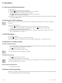
5. Maintenance
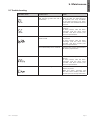
5.1 Troubleshooting
Operation status Possible cause Action
Overload
Power requirement exceeds the
UPS capacity (greater than 105 %
of nominal).
Remove some of the equipment
from the UPS. The UPS continues
to operate, but may shutdown
if the load increases. The alarm
resets when the condition becomes
inactive.
Short-circuit fault
A short-circuit occurred. Check device connection or
integrity.
If error persists, note the alarm
message and the UPS serial
number, and then contact your
service representative.
Battery fault
The batteries in the UPS are
disconnected.
Verify that all batteries are properly
connected.
If error persists, note the alarm
message and the UPS serial
number, and then contact your
service representative.
The end of battery life is reached. Contact your service representative
for battery replacement.
Fan fault
The UPS has a fan fault. Check that no object is blocking
the fan.
If error persists, note the alarm
message and the UPS serial
number, and then contact your
service representative.
Charger fault
The UPS has a charger fault. The UPS does not charge the
battery anymore.
Note the alarm message and
the UPS serial number, and then
contact your service representative.

Page 18
5SC 1 - 3 KVA US_EN
5. Maintenance
5.2 Battery-module replacement
Safety recommendations
The battery can cause electrocution and high short-circuit currents. The following safety precautions are
required before servicing the battery components:
• remove watches, rings, bracelets and all other metal objects from the hands and arms,
• use tools with an insulated handle.
A
B
A - Remove the center panel.
B - Remove the left-hand side of the front
panel.
C
C - Disconnect the battery module by
separating the two connectors.
D
D - Remove the metal protection cover in
front of the battery (one screw).
E
E - Remove the battery module and replace
it.
Mounting the new battery module
Carry out the above instructions in reverse order.
• To ensure safety and high performance, use only batteries supplied by EATON.
• Take care to firmly press together the two parts of the connector during remounting.

Page 19
5SC 1 - 3 KVA US_EN
ENGLISH
6. Appendices
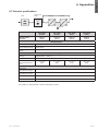
6.1 Technical specifications
5SC 1000i
Rack2U
5SC 1500i
Rack2U
5SC 2200i
RT2U
5SC 3000i
RT2U
Output Power
@ 230 V
1000 VA
700 W
1500 VA
1050 W
2200 VA
1980 W
3000 VA
2700 W
AC Input power
Rated input voltage Single phase 220-240 V
Input voltage range 184 to 276 V
Input frequency
range
45 to 55 Hz (50 Hz system), 55 to 65 Hz (60 Hz system)
Output on battery power
Voltage 220/230/240 V (-10/+6 %)
(1)
Frequency 50/60 Hz ±0.1 Hz
Battery (sealed lead
acid, maintenance
free)
2 x 12 V
9 Ah
3 x 12 V
9 Ah
4 x 12 V
9 Ah
6 x 12 V
9 Ah
Environment
Operating
temperature range
0 to 40 °C / 32 to 104 °F
Storage
temperature range
-15 to +50 °C / 5 to 122 °F
Relative humidity 20 to 90 % (without condensation)
Noise level < 45 dBA
(1) Adjustable to 220/230/240 V, must be set to the identical AC power source value.
This product is designed for IT power distribution system.
Filter
Transformer
"AVR"
Charger Inverter
Battery

Page 20
5SC 1 - 3 KVA US_EN
6. Appendices
Backup time Time during which the load can be supplied by the UPS operating on battery power.
Battery test Internal UPS test to check battery status.
Cold start The devices connected to the UPS can be started even if AC input power is not
available. The UPS operates on battery power alone.
Deep discharge Battery discharge beyond the permissible limit, resulting in irreversible damage to the
battery.
Load Devices or equipment connected to the UPS output.
Low-battery
warning
This is a battery-voltage level indicating that battery power is low and that the user
must take action in light of the imminent break in the supply of power to the load.
Normal AC
input
The AC-power line supplying the UPS under normal conditions.
Percent load Ratio of the power effectively drawn by the load to the maximum output of the UPS.
Personalisation It is possible to modify certain UPS parameters set in the factory. Certain UPS functions
can also be modified by the software to better suit user needs.
UPS Uninterruptible Power System.
UPS ON/OFF
controlled by
software
This function enables or disables initiation of UPS ON/OFF control sequences by
computer power-management software.
6.2 Glossary
-
 1
1
-
 2
2
-
 3
3
-
 4
4
-
 5
5
-
 6
6
-
 7
7
-
 8
8
-
 9
9
-
 10
10
-
 11
11
-
 12
12
-
 13
13
-
 14
14
-
 15
15
-
 16
16
-
 17
17
-
 18
18
-
 19
19
-
 20
20


Eaton 5SC 1500i Rack2U Installation and User Manual
- Type
- Installation and User Manual
- This manual is also suitable for
Ask a question and I''ll find the answer in the document
Finding information in a document is now easier with AI
Related papers
-
Eaton 5P1500R-L User manual
-
Eaton 5P750RC Installation and User Manual
-
-
Eaton 5SC1000 User manual
-
-
-
-
MGE UPS Systems Evolution 850 Tower User manual
-
-
Other documents
-
 Amano TS-3000i Installation and Operation Guide
-
SMART Technologies Board 3000i Installation guide
-
-
Worcester Climate 3000i Air Con Quick start guide
-
-
RAD Data comm 146 User manual
-
-
-
 Cypress CY7B9920 User manual
-
Add-On Computer Peripherals (ACP) ADD-MGMC-BX-DSC Datasheet

