Page is loading ...

INSTALLATION INSTRUCTIONS
Centerline or Ecoline Door Type & Undercounter Booster Element Kit
00-562448
These instructions are only intended for use by properly trained and qualified service technicians.
If you do not have technical training for this product, you should read the following procedure, in its entirety, to
determine if you have the necessary tools, instruments and skills required to perform the procedure. Procedures for
which you do not have the necessary tools, instruments and skills should be performed by a trained Hobart Service
technician.
The reproduction, transfer, sale or other use of this manual, without the express written consent of Hobart Service,
is prohibited.
NOTE: Booster element may be used on CUH / EUH 1-Phase (Undercounter) units or CDH / EDH 3-Phase or 1-
Phase (Door Type) units.
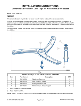
Fig. 1
BOOSTER ELEMENT KIT - 00-562448
ITEM PART NUMBER DESCRIPTION QTY
1 04-021122-001 O-Ring, ID 46.99mm x 5.33mm 1
2 00-562444 Heating Element, Booster, 6000W, 230V US 1
3 EW-231016 Temperature Probe, 10kOHM 1
4 EW-069871 Probe Holder 1
5 EW-69870 Booster Heater Cover 1
6 EW-299001 Heating Element Bridge 2
7 EW-417086 Nut, Wash Head, M6 4
8 00-942185 Hi-Limit Thermostat 233°F (112°C) ± 5°F (3°C) 2
9 00-563657 Gauge, Booster Heater 1
Brass Hardware for Element Studs to secure Element Wires
10 EW-417035 Nut, M4 x 3.2 6
11 EW-472059 Washer, M3 6
© HOBART SERVICE 2022 Page 1 of 7 F45919 Rev. A (September 2022)

BOOSTER ELEMENT KIT - 00-562448
ITEM PART NUMBER DESCRIPTION QTY
12 EW-417127 Spacer Nut, M3 x 8 4
1. DRAIN MACHINE by pressing and holding power on/off button.
NOTE: Press and holding power on/off button for 3 seconds activates self-cleaning cycle, drains machine, and
switches machine off automatically.
WARNING
Disconnect the electrical power to the machine and follow lockout / tagout procedures.
NOTE: Shut off and LOCK OUT incoming water source.
DOOR TYPE (CDH / EDH)
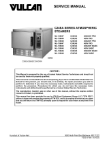
1. Remove Lower Front Panel, by locating and removing two screws on lower frame.
Fig. 2
2. Slide panel down and away from band.
Fig. 3
3. Drain Booster Tank.
NOTE: Use shop vac to remove excess water in wash tank sump housing and drain.
NOTE: Tank and Water may be EXTREMELY HOT. Allow to cool before servicing.
4. Place container under machine to catch water.
5. Loosen clamp and remove hose.
6. Continue to Booster Heater Replacement.
F45919 Rev. A (September 2022) Page 2 of 7

Fig. 4
UNDER COUNTER (CUH / EUH)
1. Remove Front Panel.
Fig. 5
2. Place container under machine to catch water.
3. Remove bolt to lower control mount bracket.
Fig. 6
Page 3 of 7 F45919 Rev. A (September 2022)

4. Drain Booster Tank.
NOTE: Use shop vac to remove excess water in wash tank sump housing and drain.
NOTE: Tank and Water may be EXTREMELY HOT. Allow to cool before servicing.
5. Place container under machine to catch water.
6. Loosen clamp and remove hose.
7. Continue to Booster Heater Replacement.
NOTE: The following procedure references the CDH / EDH (Door Type) booster images. Same procedures apply
for CUH / EUH (Undercounter).
Booster Heater Replacement
1. Remove nut securing plastic cover (1).
Fig. 7
2. Remove cover, disconnect thermistor wire at harness and remove thermistor (B2).
Fig. 8
3. Remove nuts securing heater wires and jumper bars.
NOTE: Position of the jumper bar on the booster heating element. Locations are dependant on incoming phase
wiring (3PH or 1PH).
4. Remove three nuts securing element assembly and remove assembly.
5. Clean any remaining gasket material (O-Ring) from tank opening prior to reinstallation.
F45919 Rev. A (September 2022) Page 4 of 7

Fig. 9
6. Reassemble in reverse order. Ensure O-ring (1, Fig. 1) is seated in booster element's groove. Tighten the three
new nuts (7, Fig. 1) placing even pressure against tank.
NOTE: Install Jumper Bar (6, Fig. 1) according to incoming machine phasing 3PH or 1PH using four M3x8 nuts (12,
Fig. 1) from kit.
Three Phase Wiring (3PH). Single Phase Wiring (1PH)
Fig. 10 Fig. 11
NOTE: When installing jumper bars (6, Fig. 1) on new heater assembly, ensure slotted side of the jumper bar is
facing out (Fig. 12) and the spacing between the bars is a minimum 1.6mm (1/16") gap (Fig. 13).
NOTE: Use gauge (9, Fig. 1) from kit .
NOTE: A 1/16" allen wrench may be used as a gauge.
Page 5 of 7 F45919 Rev. A (September 2022)

Slotted Side Spacing
Fig. 12 Fig. 13
7. Install heater wires to studs with washers (11, Fig. 1) and Nuts (10, Fig. 1).
NOTE: Tighten nut to 16 in*lbs. Use 7 mm wrench to hold back nut when tightening.
Fig. 14
8. Apply thermal paste to temperature probe (3, Fig. 1) and install onto probe holder (4, Fig. 1) from kit.
NOTE: Verify groove of temperature probe is at the left of the probe holder prongs as shown.
F45919 Rev. A (September 2022) Page 6 of 7

Fig. 15
9. Reinstall booster hose and tighten clamp.
10. Install terminal cover (5, Fig. 1) from kit and reattach ground wire (2, Fig. 16).
11. Apply thermal paste to hi-limit switches 3TAS and 4TAS (8, Fig. 1) from kit.
12. Install replacement hi-limit switches, 3TAS and 4TAS, and reconnect wires.
Fig. 16
13. Close up control panel (CUH / EUH only).
14. Turn on power and water source. Test unit.
NOTE: Check for leaks.
15. Install lower front cover.
Page 7 of 7 F45919 Rev. A (September 2022)
/