Page is loading ...

User Guide
MOBOTIX 2MP Vandal Fixed Dome Analytics Camera
©2021MOBOTIX AG
V1.03_12/22/2021, Order Code: Mx-VD3A-2-IR-VA

Table of Contents
Table of Contents
Table of Contents 2
Before You Start 5
Support 6
Safety Notes 6
Legal Notes 7
Overview 9
Features 10
Package Contents 11
Dimensions 12
Connecting and Installing 13
Camera Cabling 14
Camera Connectors 14
Connect Power 15
Connect Ethernet Cable 16
Connect Alarm I/O 16
Camera Installation 17
Configuration 19
System Requirements 20
Accessing the Camera 20
Setup Video Resolution 22
Exporting/Importing Configuration Files 23
Menu Reference 25
Overview 26
The Camera Menu 26
The “Home” Tab 26
Function Items on Home Page 27
The “System”Tab 29
System 30
Security 31
Network 37
DDNS 44
Mail 44
FTP 45
HTTP 45
MxMessageSystem 45
Events (Alarm Settings) 47
2 / 110

Storage Management 75
Recording 78
Schedule 79
File Location (Snapshots and Web Recording) 80
View Information 80
Factory Default 81
Software Version 82
Software Upgrade 82
Maintenance 83
The “Streaming”Tab 83
Video Configuration 84
Video Rotation 86
Video Text Overlay 86
Video ROI 87
Video ROI Encoding 88
Video OCX Protocol 88
Video Mask 89
Audio (Audio Mode and Bit Rate Settings) 89
The “Camera”Tab 90
Exposure 91
White Balance 92
Picture Adjustment 95
IR Function 96
Noise Reduction 97
WDR Function 98
Digital Zoom 98
Backlight 98
Profile 98
TV System 99
The “Logout”Tab 100
Appendix A: Installing UPnP Components 100
Appendix B: Converting IP Addresses from Decimal to Binary 100
Technical Support Information 103
Setup Internet Security 104
Technical Specifications 105
Table of Contents
3 / 110


Before You Start
Support
Support
If you need technical support, please contact your MOBOTIX dealer. If your dealer cannot help you,
he will contact the support channel to get an answer for you as quickly as possible.
If you have internet access, you can open the MOBOTIX help desk to find additional information and
software updates. Please visit:
www.mobotix.com > Support > Help Desk
Safety Notes
nThis product must not be used in locations exposed to the dangers of explosion.
nElectrical systems and equipment may only be installed, modified and maintained by a qual-
ified electrician or under the direction and supervision of a qualified electrician in accordance
with the applicable electrical guidelines. Make sure to properly set up all electrical con-
nections.
nMake sure to install this product in a well-ventilated spot and do not close off any vent open-
ings.
nDo not use this product in a dusty environment.
nProtect this product from moisture or water entering the housing.
nMake sure that you install this product as outlined in this document. A faulty installation can
damage the product!
nDo not replace batteries of the product. Batteries can explode if they are replaced by an incor-
rect type.
nThis equipment is not suitable for use in locations where children are likely to be present.
nIf using a Class I adapter, the power cord shall be connected to a socket-outlet with proper
ground connection.
nTo comply with the requirements of EN50130-4 regarding the power supply of alarm systems
for 24/7 operation, it is highly recommended to use an uninterruptible power supply (UPS)for
powering the product.
nThis equipment is to be connected only to PoE networks without routing to other networks.
6 / 110

Legal Notes
Legal Aspects of Video and Sound Recording
You must comply with all data protection regulations for video and sound monitoring when using
MOBOTIX AG products. Depending on national laws and the installation location of the cameras, the
recording of video and sound data may be subject to special documentation or it may be pro-
hibited. All users of MOBOTIX products are therefore required to familiarize themselves with all
applicable regulations and to comply with these laws. MOBOTIX AG is not liable for any illegal use of
its products.
Declaration of Conformity
The products of MOBOTIX AG are certified according to the applicable regulations of the EC and
other countries. You can find the declarations of conformity for the products of MOBOTIX AG on
www.mobotix.com under Support> Download Center> Certificates & Declarations of Con-
formity.
RoHS Declaration
The products of MOBOTIX AG are in full compliance with European Unions Restrictions of the Use of
Certain Hazardous Substances in Electrical and Electronic Equipment (RoHS Directive 2011/65/EC)
as far as they are subject to these regulations (for the RoHS Declaration of MOBOTIX, please see
www.mobotix.com, Support> Download Center> Documentation> Brochures & Guides> Cer-
tificates).
Disposal
Electrical and electronic products contain many valuable materials. For this reason, we recommend
that you dispose of MOBOTIX products at the end of their service life in accordance with all legal
requirements and regulations (or deposit these products at a municipal collection center). MOBOTIX
products must not be disposed of in household waste! If the product contains a battery, please dis-
pose of the battery separately (the corresponding product manuals contain specific directions if the
product contains a battery).
Disclaimer
MOBOTIX AG does not assume any responsibility for damages, which are the result of improper use
or failure to comply to the manuals or the applicable rules and regulations. Our General Terms and
Conditions apply. You can download the current version of the General Terms and Conditions
from our website at www.mobotix.com by clicking on the corresponding link at the bottom of every
page.
Before You Start
Legal Notes
7 / 110


9 / 110
Overview
The Vandal Analytics Series is capable of supporting up to WDR Vandal Analytics @30fps/720p
@30fps (WDR off Vandal Analytics @ 60 fps/720p @60 fps) video streaming. Moreover, combined
with the latest WDR technology and low-light technology, the Vandal Analytics Series is able to
deliver high quality images in the dark, low light condition.
Vandal Analytics H.265 IR Rugged Dome Camera is designed to withstand ever-changing outdoor
environment and is compliant with IP66 and IK10 standard. It is equipped with IR LED with an
effective distance of up to 40 meters to ensure its usability under poor lighting condition. The
camera operating temperature ranges from –40 to 60°C/–40 to 140°F.
To make use of the camera’s advanced video analytics capabilities, please consult the Intro-
duction to Video Analytics with MOBOTIXMOVE Cameras manual available on
www.mobotix.com> Support> Download Center> Marketing &Documentation> Manuals.
2

Overview
Features
Features
nMultiple Progressive Scan CMOS Sensor Support of up to 1920x1080 (2MP)px resolution
nMulti Exposure WDR
nMulti Codec Support (H.265/H.264/MJPEG)
nLow Latency Streaming
nQuad Streams Support
nTrue Day/Night Function (ICR)
nIR LED (Working Distance up to 40m)
n3D Motion Compensated Noise Reduction (MCTF)
nSmart Event Functions:
nExternal Input/Motion Detection/Network Failure Detection
nTampering Alarm/Periodical Event/Manual Trigger/Audio Detection
nText Overlay and Privacy Masks
nMicro SD/ SDHC/ SDXC Card Support
nONVIF Profile S/G/T/M Support
nSmart Low Bitrate Control
nWeatherproof (IP66)
nVandal Proof (IK10 Rating)
10 / 110

Package Contents
Check the package for the items listed below.
nQuick Guide
nVandal Analytics H.265
IR Rugged Dome Camera
n
4-Pin Power Terminal Block
n
Cable Gland
n
Self-Tapping Screws (x2)
n
Plastic Dowel (x2)
n
Security Torx
Overview
Package Contents
11 / 110

Overview
Dimensions
NOTE! Users MUST pre-drill and use plastic anchors before fastening the supplied self-tapping
screws on the wall
CAUTION!
Do not replace batteries of the camera. Risk of explosion may occur if the battery is replaced by an
incorrect type.
Dimensions
The dimensions of the camera are shown below.
12 / 110


Connecting and Installing
Camera Cabling
Camera Cabling
Before users connect cables, make sure that all cables and the power adapter are placed in dry and
well-waterproofed environments, e.g. waterproof boxes. The purpose is to prevent moisture accu-
mulation inside the camera and moisture penetration into cables, which might lead to device break-
down. Please refer to the following sections for camera connection.
NOTE!
This camera must be installed by qualified personnel and the installation should conform to all
local codes.
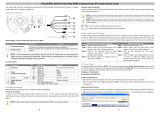
Camera Connectors
14 / 110

No. Connector Pin Definition Remarks
1RJ-45 - For network and PoE connections
2BNC* 1 BNC For analog video output
2 GND
3Power
(DC 12V /
AC 24V)
1 AC 24V 1 Power connection
2 AC 24V 2
3 DC 12V 1
4 DC 12V 2
4Default
Button
- Press the default button with a proper tool for at least 20 seconds to
restore the camera.
5microSD
Card Slot
- Insert the microSD card into the card slot to store videos and snapshots.
Do not remove the microSD card when the camera is powered on.
6Alarm &
Audio I/O
1 Audio In L Audio In (Line In)
2 Audio In R
3 GND Ground connection
4 Audio Out L Audio Out (Line Out)
5 Audio Out R
6 Alarm Out + Alarm connection>
Do NOT connect external power supply
to the alarm I/O connector of the IP cam-
era.
7 Alarm Out −
8 Alarm In +
9 Alarm In −
*Contact the manufacturer for the compatible BNC cable.
NOTE! It is not recommended to record with the microSD card for 24/7 continuously, as it may
not be able to support long term continuous data read / write. Please contact the manufacturer of
the microSD card for information regarding the reliability and life expectancy of the product.
Connect Power
For power connection, refer to section Connectors. Alternatively, users can power the camera by
PoE if a Power Sourcing Equipment (PSE) switch is available. Refer to the section below for Ethernet
Connecting and Installing
Connect Power
15 / 110

Connecting and Installing
Connect Ethernet Cable
cable connection.
NOTE! If the device is powered over Ethernet, make sure the PSE is connected to the network.
Connect Ethernet Cable
To have best transmission quality, cable length shall not exceed 100 meters. Connect one end of the
Ethernet Cable to the RJ-45 connector of the camera, and plug the other end of the cable to the net-
work switch or PC.
NOTE! In some cases, Ethernet crossover cable might be needed when connecting the IP camera
directly to PC.
nCheck the status of the link indicator and activity indicator LEDs. If the LEDs are unlit, please
check the LAN connection.
nGreen Link Light indicates good network connection.O
nOrange Activity Light flashes for network activity indication.
Connect Alarm I/O
The camera supports one alarm input and one relay output for alarm application. Refer to section
Connectors for pin definitions.
NOTE! Do NOT connect external power supply to the alarm I/O connector of the IP camera.
16 / 110

Camera Installation
The following description demonstrates how to directly install the camera to the ceiling or to the
wall.
1. Loosen the two security screws on the cam-
era with the supplied security torx and
open the dome cover.
2. Open the back conduit entry block using a
coin and place it to the side conduit entry.
3. Place the camera at the installation loc-
ation. Mark the position of the two screw
holes and the back conduit entry (for cable
entry use) indicated in the right figure on
the ceiling or wall.
Connecting and Installing
Camera Installation
17 / 110

Connecting and Installing
Camera Installation
4. On the ceiling or wall, drill the cable entry
hole (back conduit entry).
5. Drill a hole slightly smaller than the supplied plastic screw anchor on each marked screw hole.
Then insert the plastic screw anchors into the drilled holes.
6. Thread the cables through the cable entry hole. Match the two screw holes on the camera with
the plastic screw anchors at the installation location. Fasten the camera with the supplied self-
tapping screws.
7. Attach the dome cover to the camera and fasten the two security screws.
18 / 110


Configuration
System Requirements
System Requirements
To perform the IP camera via web browser, please ensure the PC is in good network connection and
meets system requirements as described below.
Items System requirements
Personal Computer Minimum:
nIntel® Core™ i5-2430M @ 2.4 GHz
n4 GB RAM
Recommended :
nIntel® Core™ i7-870 @ 2.93 GHz
n8 GB RAM
Operating System Windows 7 or later operating system
Web Browser Microsoft Internet Explorer 11.0
Chrome
Firefox
Safari
Network Card 10Base-T (10 Mbps), 100Base-TX (100 Mbps) or 1000Base-T operation
Viewer ActiveX control plug-in for Microsoft IE
NOTE! The ITE is to be connected only to PoE networks without routing to the outside plant or
equivalent description.
Accessing the Camera
Accessing the Camera
The 2MP Vandal Fixed Dome Analytics Camera supports all current browsers without requiring any
additional plug-in or add-on (e. g. for H.264 / MJPEG support). Microsoft Internet Explorerwith Act-
iveX is recommended for best performance and H.265 support
A client program will be automatically installed to the PC when connecting to the camera. If using
Microsoft Internet Explorer, ensure downloading the ActiveX control is allowed by either changing the
ActiveX controls and plug-in/add-on (H.264 and MJPEG) or setting Internet’s security level to default.
20 / 110
/