Page is loading ...

i
PNA296
Portable Network
Analyzer
Installation & Operation
Manual
BG0296 REV.A2

PNA296
Portable Network
Analyzer
Installation and
Operation Manual

i
LIMITED WARRANTY
The manufacturer offers the customer a 24-month functional warranty on
the instrument for faulty workmanship or parts from date of dispatch from
the distributor. In all cases, this warranty is valid for 36 months from the
date of production. This warranty is on a return to factory basis.
The manufacturer does not accept liability for any damage caused by
instrument malfunction. The manufacturer accepts no responsibility for
the suitability of the instrument to the application for which it was
purchased.
Failure to install, setup or operate the instrument according to the
instructions herein will void the warranty.
Your instrument may be opened only by a duly authorized representative of
the manufacturer. The unit should only be opened in a fully anti-static
environment. Failure to do so may damage the electronic components
and will void the warranty.
NOTE
The greatest care has been taken to manufacture and calibrate your
instrument. However, these instructions do not cover all possible
contingencies that may arise during installation, operation or
maintenance, and not all details and variations of this equipment are
covered by these instructions.
For additional information regarding installation, operation or
maintenance of this instrument, contact the manufacturer or your local
representative or distributor.
This manual provides instructions for using the PNA296. For instructions
and information on using the PM296 and the accompanying PAS295
software package, you are advised to refer to the relevant user's manuals.
BG0296 REV. A2

ii
Table of Contents
1 The Portable Network Analyzer ________________________________1
2 Installation_________________________________________________4
2.1 Location ______________________________________________4
2.2 Connecting to the Electrical Network ________________________4
2.3 Wiring Mode Setup _____________________________________4
2.3.1 Using Standard Current Clamps_________________________5
2.3.2 Using Standard Current Clamps with Special Cables_________5
2.4 Current Transformer Setup________________________________6
2.4.1 Direct Measurement (Clamps) __________________________6
2.4.2 Measurement via External CTs (Clamps + Special Cable) _____6
2.5 Potential Transformer Setup_______________________________7
2.6 Voltage Probes Connection _______________________________7
2.7 Current Sensors Connection ______________________________7
2.7.1 Standard Clamps ____________________________________8
2.7.2 Special Cables ______________________________________8
2.7.3 Standard FLEX Current Sensors _________________________8
3 Power Supply ______________________________________________9
3.1 External Power Supply ___________________________________9
3.2 Internal Battery Power Supply______________________________9
3.3 Indicators ____________________________________________10
Appendix: Chauvin Arnoux Current Clamps for PNA296_______________23
Table of Figures
1-1 Standard Contents of PNA296 ..............................................................................2
1-2 Detail of Nos. 8 and 11 in Figure 1-1....................................................................3
1-3 Additional Optional Items.......................................................................................3
2-1 3-Wire System Direct Connection ........................................................................11
2-2 3-Wire System Direct Connection for THD and Harmonic Measurement.....12
2-3 4-Wire System Direct Connection.........................................................................13
2-4 4-Wire Grounded Delta System Direct Connection ..........................................14
2-5 3-Wire System Direct Connection, Using Standard Current Clamps with
Cables.......................................................................................................................15
2-6 3-Wire System Direct Connection for THD and Harmonic
Measurement, Using Standard Clamps with Cables .......................................16

iii
Table of Figures (continued)
2-7 4-Wire System Direct Connection, Using Standard Clamps with Cables.....17
2-8 4-Wire Grounded Delta System Direct Connection for THD and
Harmonic Measurement, Using Standard Clamps with Cables....................18
2-9 3-Wire System Connection via External PT and CT, Using Standard
Clamps with Cables ...............................................................................................19
2-10 4-Wire System Connection via External PT and CT, Using Standard
Clamps with Cables ...............................................................................................20
2-11 3-Wire Open Delta 2 ½ Element Connection via 2 External
PTs and 3 External CTs, Using Standard Clamps with Cables .....................21
2-12 4-Wire Wye 2 ½ Element Connection via 2 External PTs and 3
External CTs, Using Standard Clamps with Cables.........................................22

1
1 The Portable Network Analyzer
1.
The PNA296 Portable Network Analyzer measures, records and analyzes
parameters of electrical networks. Being mobile, it enhances efficiency by
enabling on-site identification of power problems. The PNA296 meets the
requirements of a wide range of applications, from power quality analysis to
energy auditing and load profile recording over a period of time.
The PNA296 includes all the measuring, logging and analyzing capabilities
of the PM296 Power Quality Analyzer in a convenient, portable package. The
manufacturer’s PAS295 software package included in the PNA296 provides
graphic data display and analysis capabilities.
The PNA296 is suitable for direct measurement of voltages up to 660V (or
greater when using a Potential Transformer). The PNA296 is equipped with
standard clamps with secondary current of 1A. It is also possible to use
FLEX sensors with secondary voltage of 3VAC or standard clamps with
secondary voltage up to 3VAC.
A unique advantage offered by the PNA296 is its ability to measure small
currents, in the range of 100mA to 10A, in addition to the standard ranges,
using standard high current clamps, with a high degree of accuracy. This
additional measurement capability is made possible by the manufacturer's
special cables and electronic circuit used with standard current clamps.
This combination also enables the PNA296 to perform current
measurements on high voltage lines via current transformers, by
measuring the secondary output of the external CT with 5A nominal
secondary current.
The PNA296 accuracy is a function of the accuracies of the PM296, the
clamps and the external transformers (PT and CT). Most of the PNA296
measurement error is due to the latter two elements.
The PNA296 has an internal DC battery which enables it to continue
working even when the power supply is disconnected for short intervals, as
in a power failure.
The contents of the PNA296 case are shown in Figures 1-1, 1-2 and 1-3.
Section 2 of this manual provides installation instructions, including wiring
mode, CT and PT setup, as well as connection of voltage probes and
current sensors. Section 3 provides information on the internal battery and
an explanation of the PNA296 indicator lights.

2
Current
II
V
II
V
V
Voltage
V
PORTABLE NETWORK ANALYZER PNA296
14
6
PM296
USER GUIDE
7
8
PAS295
PNA296
12
10
9
11
13a
13c
13b
15 16
1
00-12006/1
17
5
PAS295
3
4
ASCII
MODBUS
2
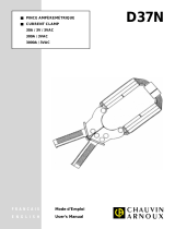
Figure 1-1 Standard Contents of PNA296
1 PNA296 Display
2 PAS295 Software, Modbus and ASCII Reference Guides (diskettes)
3 Voltage V1, V2, V3, VN inputs - Banana Connections
4 Current Sensors I1, I2, I3, IAux Inputs - Sockets
5 Voltage Probe Set (1 black, 3 red, spring-loaded)
6 Current Clamps Set
7 Manuals: PNA296, PM296, PAS295
8 PM296 Relays Connector - see Figure 1-2 for detail
9 Power Supply Socket & Fuse Housing (100 to 240 VAC)
10 Power Supply Cord
11 PM296 Status Inputs Connector - see Figure 1-2 for detail
12 Slide Switch operating Voltage Supply
13a AC Power lamp
(green)
13b Battery lamp “BAT”
(red)
13c Low battery lamp “BAT LOW”
(red, blinking) and buzzer
14 Communication Port (RS-232)
15 Communication Cable (RS-232)
16 Battery and Battery Fuse
17 Case for Clamps and Cables

3
12345678
STATUS INPUTS:
6 108 12 14 16 18 20 11
COMMON
1922 24 2826
192622 25
K3K2K1 K4
212824 2723
21 23 2725
K1 K2 K3 K4
c00-12008-2
NOT
CONNECTED
RELAYS
Figure 1-2 Detail of Nos. 8 and 11 in Figure 1-1
Figure 1-3 Additional Optional Items
1
Connection Cables for FLEX Current Sensors and for Clamps with
voltage output
2
Special Cables for Current Clamps for low current measurement (100mA -
10A)
NOTE:
Connections for
relays and status inputs
are the same as for the
PM296. See the PM296
Installation and Operation
Manual for connection
drawings and instructions.

4
2 Installation
2.
Read through this section carefully before connecting the
PNA296 to the circuit being tested.
2.1 Location
Place the PNA296 at least half a meter (1.6 feet) from current lines carrying
up to 600A, and at least one meter (3.3 feet) for currents between 600A and
2000A.
2.2 Connecting to the Electrical Network
Connect the PNA296 to the AC power supply using the Power Supply Cord
(No. 10 in Figure 1-1). Turn the slide switch (No. 12 in Figure 1-1) ON.
2.3 Wiring Mode Setup
Set the wiring mode on the PM296. Select one of the following seven wiring
configurations.
For setup of the wiring mode directly on the PM296 front panel, refer to Table
4-1 of the PM296 User’s Guide.
For setup of the wiring mode using the PAS295 software, refer to section
4.2.1 of the PAS295 User’s Guide.
Wiring Configuration
'Wiring Mode'
3-wire direct connection using 2 CTs (2-element) 3dir
3-wire open delta connection using 2 PTs and 2 CTs (2-
element)
3OP2
3-wire open delta connection using 2 PTs and 3 CTs (2½-
element)
3OP3
4-wire Wye direct connection using 3 CTs (3-element) 4LL3 or 4Ln3
4-wire delta direct connection using 3 CTs (3-element) 4LL3 or 4Ln3
4-wire Wye connection using 3 PTs and 3 CTs (3-element) 4LL3 or 4Ln3
4-wire Wye connection using 2 PTs and 3 CTs (2½-
element)
3LL3 or 3Ln3
Note: Even if measuring one phase current only, all current sensors must
be connected, to avoid noise or other disturbances.

5
2.3.1 Using Standard Current Clamps
The following connections are recommended:
Wiring Configuration Wiring Mode Drawing
3-wire configuration with direct
connection
3dir Figure 2-1
3-wire system direct connection for THD
and harmonic measurements
3dir Figure 2-2
4-wire system configuration with direct
connection
4LL3/4Ln3 Figure 2-3
4-wire delta system direct connection 4LL3/4Ln3 Figure 2-4
Note: The same connections apply when using FLEX sensors.
2.3.2 Using Standard Current Clamps with Special
Cables
The following connections are recommended:
Wiring Configuration Wiring Mode Figure
3-wire configuration with direct
connection
3dir Figure 2-5
3-wire system direct connection for
THD and harmonic measurements
3dir Figure 2-6
4-wire system configuration with
direct connection
4LL3/4Ln3 Figure 2-7
4-wire delta system direct connection
4LL3/4Ln3 Figure 2-8
3-wire system connection via
external PT and CT
3OP2 Figure 2-9
4-wire system connection via
external PT and CT
4LL3/4Ln3 Figure 2-10
3-wire open delta, 2½-element
connection using 2 PTs and 3 CTs
3OP3 Figure 2-11
4-wire Wye, 2½-element connection
using 2 PTs and 3 CTs
3LL3/3Ln3 Figure 2-12

6
2.4 Current Transformer Setup
Set the CT according to the PM296 User’s Guide Rev. A1, Table 4-1 or in the
PAS295 User’s Guide Rev. A1, Section 4.2.1.
2.4.1 Direct Measurement (Clamps)
All clamps require the CT to be set according to:
CT = I1ncl / I2ncl
where I1ncl and I2ncl are the clamp nominal primary and secondary currents.
Examples: 1) I1ncl =1000A and I2ncl =1A, CT=1000
2) I1ncl =1000A and I2ncl =5A, CT=200
FLEX sensors and clamps with voltage V2ncl as an output signal with
sensitivity S= V2ncl / I1ncl [V/A], require the CT to be set according to:
CT= 6/S
Example: I1ncl =200A, V2ncl = 2V, [ S=2V/200A=0.01V/A ],
CT=6/0.01=600
2.4.2 Measurement via External CTs (Clamps +
Special Cable)
The CT value should be set according to the following formula:
CT = (Ip / Is ) • (I1ncl / I2ncl) • 0.005
where:
Ip = external Current Transformer primary nominal current
Is = external Current Transformer secondary nominal current
Examples:
1. When measurement is of current without external transformer (Ip / Is=1) via
clamp 1000/1, then
CT=5, but for accuracy measuring must be set CT=5000 and on
the instrument display current will be displayed in mA;
2. When measurement is of secondary of current transformer 3000/5 via
clamp 1000/1, then
IP = 3000, IS = 5, Ic=1000, C.T. = (3000/5) • (1000/1) • 0.005 = 3000.
3. When measurement is of secondary of current transformer 5000/1 via
clamp 120/0.12, then
IP = 5000, IS = 1, C.T. = (5000/1)• (120/0.12) • 0.005 = 25,000.

7
2.5 Potential Transformer Setup
Set the PT according to the PM296 User’s Guide Rev. A1, Section 4.1 or the
PAS295 User’s Guide Rev. A1, Section 4.2.1.
2.6 Voltage Probes Connection
Connect the voltage probes to the PNA296 through the voltage connectors
marked V1/V2/V3/VN. Connect the probes to the line conductors according
to the power system configuration. (An optional set of extension cables for
the voltage probes may be ordered.).
WARNING
The voltage between phases V1, V2, V3 should not exceed 660
VAC RMS (900 VAC peak).
2.7 Current Sensors Connection
Connect the current sensors first to the PNA296 and then to the
measured circuit. The optional set of extension cables, 3 meters in length,
can be used with all current sensors.
There is a common connector for all types of current sensors in each phase.
NOTE: The nominal secondary inputs of the current sensors can be 1A or
5V.
WARNING
All clamps provided with the PNA296 include special protection
against overvoltage. If you use clamps other than those
provided with the PNA296, do not under any circumstances
disconnect the current clamps from their sockets while the
clamps are connected to the electrical wires. This can cause
fatal injury and equipment damage.

8
2.7.1 Standard Clamps
The PNA296 contains a set of standard current clamps with 1A secondary
nominal current and primary nominal current according to the order
specification (120A / 1000A / 3000A).
Maximum PNA296 measured current is 200% of the nominal current.
All current clamps in the kit have built-in protection against clamp connector
disconnection. See the Appendix for a description of the current clamps.
2.7.2 Special Cables
The manufacturer's special cables, together with the standard clamps,
enable the PNA296 to perform measurements of high voltage lines via
current transformers by measuring the secondary output of the external CT
with 5A nominal secondary current.
NOTE: Using clamp 1000A via the special cable will yield greater
measurement accuracy than using the 120A clamp.
2.7.3 Standard FLEX Current Sensors
The PNA296 can work with all standard FLEX and clamp current sensors
which have a voltage output signal 1 Volt / 10q A, where q = any whole
number. Maximum measured current is 200% of the nominal current. The
PNA296 provides an optional FLEX connector cable for connection to these
current sensors.

9
3 Power Supply
3.
WARNING
Turn the slide switch OFF when not in use.
3.1 External Power Supply
The PNA296 external power supply is 100 to 240 VAC, 45 to 65 Hz, 15 VA.
3.2 Internal Battery Power Supply
The PNA296 includes a rechargeable battery (12V/1.2Ah DC battery, Yuasa
NP1.2-12). When fully charged, the battery allows the PNA296 to work for at
least 20 minutes. Do not allow the battery to totally discharge.
Battery Storage
Long-term storage of the battery is according to the following:
Storage temperature +10°C +20°C +30°C +40°C
Time before recharging
required, in months
> 18 14 8 5
Charging the Battery
There are 3 indications that the battery is fully discharged: a buzzer sound, a
blinking LOW BAT lamp, and no display. Apply AC voltage to the PNA296 to
recharge the battery. The recommended charge time is 8 hours, which will
allow at least 20 minutes of work.
ATTENTION
For reconnection to the AC network and charging, turn the instrument slide
switch OFF, wait approximately 5 minutes and then turn it ON again.

10
3.3 Indicators
The following table lists the possible indicated conditions:
Green
Lamp-
"AC"
Red
Lamp-
"BAT"
Red
Lamp-
"LOW
BAT"
PM296
Display
Meaning
ON OFF OFF ON PNA296 supplied by external
AC power supply; battery is
charging slowly
OFF ON OFF ON PNA296 supplied by internal
charged DC battery
OFF ON Blinking
(buzzer
also
sounds)
ON PNA296 supplied by internal DC
power supply; battery needs
charging and will disconnect
automatically within 5 minutes
ON OFF OFF OFF PNA296 is connected to
external AC power supply, slide
switch is OFF; battery is
charging rapidly
3.4 Measuring Battery Voltage
Battery voltage Vbat is displayed in the DC VOLTAGE window on page 3 of
the instrument display.
If Vbat = 12V, the battery is at normal operation. If Vbat = 11V, the battery is
LOW. If Vbat = 10.5V the battery is discharged and will no longer operate.

11
WIRING DIAGRAMS (Figures 2-1 through 2-12)
Current Voltage
"
(C)L3
(A)
(B)
L1
LINE
L2
I""
I
I3
1
"
I
"
00-12007/2
CURRENT
DIRECTION
"
ICLAMP
BLACK
RED
RED
RED
2VV1V3
LOAD
Figure 2-1 PNA296 Connections for 3-Wire System Direct Connection

12
CLAMP
DIRECTION
"
"I
BLACK
CURRENT
00-12007/3
RED
RED
RED
LINE
(A)
L1
(C)L3
(B)L2
I3
I1
"
I
I
""
"
V
2
V
1V
VN
3
LOAD
Figure 2-2 PNA296 Connections for 3-Wire System Direct Connection for THD and Harmonic Measurement

13
BLACK
I
A
UX
"
I
"
DIRECTION
CLAMP
CURRENT
"
(A)
(C)
N
(B)L2
L1
LINE
L3 I
" "
3I
"I"
I""
1I
I2
"
I
00-12007/4
RED
RED
RED
2V
1
V
V
3V
N
LOAD
Figure 2-3 PNA296 Connections for 4-Wire System Direct Connection

14
DIRECTION
CURRENT
(B)
delta connection
VOLTAGES DISPLAYED:
2. Line to line voltages: 240V.
1. Line to neutral voltages: 120V; 208V; 120V.
1
L
120V
(A)
N
240V
208V
2
L
Grounded
N
"I"CLAMP
BLACK
120V
3
L(C)
240V
RED
RED RED
VV1V
2V3N
II UXA
00-12007/5
2I I 1
I
3
L
*
*2
L
L1
*
(B)
(A)
(C)
120V AC
240V AC
L3
N
240V AC
L2240V AC
120V AC
208V AC
3
L
2
L
1
L1
L
N"
I
"
" "
I
"
LOAD
"
"
I
"
Figure 2-4 PNA296 Connections for 4-Wire Grounded Delta System Direct Connection

15
EQUIPMENT
EXISTING
"I"DIRECTION
CLAMP CURRENT
I3
"I"
I1
RED
SPECIAL CABLES
BLACK
00-12005/1
RED
RED
(C)
(B)
(A)
MEASUREMENT
L3
LINE L2
L1
-
L
" "
I
I3
K
+
I1
CT
-
K
+
CT
L
V2
V
1 3V
LOAD
Figure 2-5 PNA296 Connections for 3-Wire System Direct Connection, Using Standard Current Clamps with
Manufacturer's Special Cables
/