Page is loading ...

- 1 -
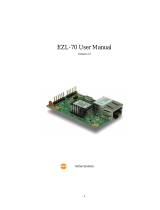
EZL-50L / EZL-50M
User Manual
Version 3.5
Sollae Systems

- 2 -
To all residents of the European Union
Important environmental information about this product
This symbol on this unit or the package indicates that disposal of this unit after its
lifecycle could harm the environment. Do not dispose of the unit as unsorted municipal
waste; it should be brought to a specialized company for recycling. It is your responsibility to
return this unit to your local recycling service. Respect your local environmental regulation. If in
doubt, contact your local waste disposal authorities.

- 3 -
- Table of Contents –
1. OVERVIEW ..................................................................................................................... - 6 -
1.1. OVERVIEW ...................................................................................................................... - 6 -
1.2. COMPONENTS.................................................................................................................. - 7 -
1.3. SPECIFICATIONS .............................................................................................................. - 7 -
1.4. INTERFACE ...................................................................................................................... - 8 -
1.4.1. Dimension ..................................................................................................................... - 8 -
1.4.2. Pin Configuration .......................................................................................................... - 8 -
1.4.3. DC Electrical Characteristics ..................................................................................... - 10 -
1.4.4. Power ...........................................................................................................................- 11 -
1.4.5. Ethernet Interface .........................................................................................................- 11 -
1.4.6. I/O Interface ................................................................................................................ - 12 -
1.4.7. Ethernet Address (MAC address) ................................................................................ - 12 -
1.4.8. Hardware Flow control (RTS/CTS) ............................................................................. - 12 -
1.5. THE EVALUATION BOARD SET ...................................................................................... - 13 -
1.5.1. Components ................................................................................................................. - 13 -
1.5.2. The Explanation of EVB .............................................................................................. - 13 -
2. INSTALLATION AND TEST RUN ............................................................................. - 14 -
2.1. INSTALLATION METHOD ................................................................................................ - 14 -
2.1.1. Checking the Communication Environment ................................................................ - 14 -
2.1.2. Connecting to the Network .......................................................................................... - 14 -
2.1.3. Configuring the Environmental Variables ................................................................... - 15 -
2.2. TEST.............................................................................................................................. - 15 -
2.2.1. Changing PC IP Address ............................................................................................. - 15 -
2.2.2. Installation EZL-50L/M............................................................................................... - 15 -
2.2.3. Configuring EZL-50L/M ............................................................................................. - 15 -
2.2.4. Connecting to the PC Serial Port ................................................................................ - 16 -
2.2.5. Communication Test .................................................................................................... - 16 -
3. CONFIGURING IP ADDRESS AND ENVIRONMENTAL VARIABLES .............. - 17 -
3.1. IP ADDRESS AND ENVIRONMENTAL VARIABLES ............................................................ - 17 -
3.2. CONFIGURATION BY EZCONFIG ..................................................................................... - 22 -
3.2.1. ezConfig Menu ............................................................................................................ - 22 -
3.3. AT COMMAND ............................................................................................................... - 23 -
3.4. SETTING IP ADDRESS-RELATED ITEMS BY DHCP ......................................................... - 23 -

- 4 -
3.5. SETTING IP ADDRESS-RELATED ITEMS BY PPPOE ........................................................ - 23 -
4. OPERATION MODE .................................................................................................... - 24 -
4.1. OPERATION MODE OVERVIEW ...................................................................................... - 24 -
4.1.1. Overview ..................................................................................................................... - 24 -
4.2. HOW TO INITIATE EACH OPERATION MODE .................................................................. - 24 -
4.2.1. How to Initiate Normal Mode ..................................................................................... - 24 -
4.2.2. Entering ISP Mode ...................................................................................................... - 24 -
4.2.3. Comparison of Operation Modes ................................................................................ - 24 -
4.3. NORMAL MODE ............................................................................................................. - 25 -
4.4. ISP MODE ..................................................................................................................... - 26 -
5. NORMAL MODE .......................................................................................................... - 28 -
5.1. T2S – TCP SERVER ....................................................................................................... - 28 -
5.2. ATC .............................................................................................................................. - 30 -
5.3. COD – TCP CLIENT ...................................................................................................... - 32 -
5.4. U2S – UDP ................................................................................................................... - 34 -
6. ATC MODE.................................................................................................................... - 36 -
6.1. OVERVIEW .................................................................................................................... - 36 -
6.1.1. AT command format .................................................................................................... - 36 -
6.2. BASIC AT COMMAND SET (EXAMPLE: ATA, ATD ETC.) ................................................ - 37 -
6.3. EXTENDED AT COMMAND SET (EXAMPLE: AT+PLIP ETC.) .......................................... - 38 -
6.4. ON-LINE STATE AND COMMAND STATE ......................................................................... - 38 -
6.4.1. Changing to Command State from On-line State ........................................................ - 39 -
6.4.2. Changing to On-line State from Command State......................................................... - 39 -
6.5. CONFIGURE WITH BASIC AT COMMANDS ...................................................................... - 40 -
6.6. CONFIGURE WITH EXTENDED AT COMMANDS .............................................................. - 41 -
6.7. EXAMPLE OF TCP CONNECTION ................................................................................... - 42 -
6.7.1. Example for Active Connection – TCP Client ............................................................. - 42 -
6.7.2. Example for passive Connection – TCP Server ........................................................... - 42 -
6.8. EXAMPLE FOR TCP DISCONNECTION ............................................................................ - 43 -
6.8.1. Example for active disconnection ................................................................................ - 43 -
6.8.2. Example for passive disconnection ............................................................................. - 43 -
6.9. EXAMPLE OF PING TEST .............................................................................................. - 43 -
7. TECHNICAL SUPPORT, WARRANTY, AND PRECAUTIONS ............................. - 44 -
7.1. TECHNICAL SUPPORT .................................................................................................... - 44 -

- 5 -
7.2. WARRANTY .................................................................................................................. - 44 -
7.2.1. Refund ......................................................................................................................... - 44 -
7.2.2. Free A/S ....................................................................................................................... - 44 -
7.2.3. Charged A/S ................................................................................................................ - 44 -
7.3. PRECAUTIONS ............................................................................................................... - 44 -
8. ORDERING INFORMATION ..................................................................................... - 45 -
9. REVISION HISTORY .................................................................................................. - 46 -

- 6 -
1. Overview
1.1. Overview
Along with the development of the Internet, the demand for data communication
functions has increased recently. Data communication over the Internet requires using
TCP/IP, the Internet communication protocol. That is to say, in order to connect a
system to the Internet, TCP/IP protocol must be implemented. It is possible to
implement TCP/IP by directly implementing the protocol, porting public TCP/IP, or
using Operating System (OS). However, all these methods impose burdens on the
developer in time, cost, and technology.
EzTCP series, a Serial ↔ TCP/IP protocol converter product group of Sollae Systems,
enables you to use TCP/IP communication (the Internet communication) function simply
by “connecting the cable to a serial port”. EzTCP sends data from the serial port to the
Internet network after TCP/IP processing, and vice versa.
EZL-50L/M / EZL-50M in ezTCP product group are products that provide TCP/IP
communication through Ethernet. In other words, like other ezTCP products, EZL-50L /
EZL-50M send data from the serial port to the LAN after TCP/IP processing and vice
versa.
It provides DHCP and PPPoE functions as well as TCP/UDP/IP, so that it can be applied
to the cable network and the xDSL network.
EZL-50L / EZL-50M are modular and embedded types that are embedded in user’s systems.
EZL-50L(A) / EZL-50M(A) replace EZL-50L / EZL-50M because the CPU of EZL-
50L / EZL-50M, ATmega64L, is discontinued. EZL-50L(A) / EZL-50M(A) use
ATmega64A and are manufactured after the first half of 2010. The new products are
the same with the previous products except for only few things. Those are amount of
current consumption and electrical characteristics.

- 7 -
1.2. Components
EZL-50L/M Body
RJ-45 with pulse-transformer (optional)
EZL-50 Evaluation set (optional)
5V Power adapter (optional)
1.3. Specifications
Power
Input Voltage
5V (±5%)
Current
Consumption
(typical)
EZL-50L / EZL-50M: 55 / 61 mA
EZL-50L(A) / EZL-50M(A): 49 / 55 mA
Dimension
50mm x 32mm x 11mm
Weight
about 10g
Memory
EZL-50L : Flash – 64K, SRAM – 4K
EZL-50M : Flash – 64K, SRAM – 32K
Interface
Serial
2mm pitch 1x12 connector
Network
2mm pitch 1x12 connector
Serial Port
UART (1,200bps ~ 115,200bps)
Network
10Base-T Ethernet
Protocols
TCP, UDP, IP, ICMP, ARP, DHCP, PPPoE
Communication
Mode
T2S
TCP Server Mode
COD
TCP Client Mode
ATC
TCP Server/Client Mode
(AT command emulation)
U2S
UDP
Utilities
ezConfig
Configuration utility via LAN
ezTerm
Socket test utility
hotflash
Firmware download utility via TFTP
You can download free utilities and firmware from http://www.eztcp.com
The difference between EZL-50L and EZL-50M is the SRAM size.
We are going to call as EZL-50L/M for both EZL-50L and EZL-50M in
convenience.

- 8 -
1.4. Interface
1.4.1. Dimension
1.4.2. Pin Configuration
PIN NAME
Function
Dir.
Mandatory
Recommended
connection
Optio
n
VCC
Power Input (DC 5V)
-
●
GND
Ground
-
●
TP_IN+
10Base-T Differential
Input +
IN
●
TP_IN-
10Base-T Differential
Input -
IN
●
TP_OUT-
10Base-T Differential
Output -
OUT
●
TP_OUT+
10Base-T Differential
Output +
OUT
●
RX_LED+
10Base-T RX LED
OUT
●
●
TX_LED+
10Base-T TX LED
OUT
●
●
LINK_LED-
10Base-T Link LED
OUT
●
●
STATUS
EZL-50L/M Status
OUT
●
●
RST+
Reset(Active High)
IN
●
P0
Connect Notification
(During TCP
OUT
●
●

- 9 -
Connection : Low)
P1
TXDE, for interface
with RS485
When sending to the
UART: HIGH
OUT
●
ISP-
In System
Programming
(Active Low)
IN
●
●
TxD
UART TxD
OUT
●
RTS
UART RTS
OUT
●
RxD
UART RxD
IN
●
CTS
UART CTS
IN
●
It is OK that [Recommended Connection] is not connected, but we strongly
recommend that connect them.

- 10 -
1.4.3. DC Electrical Characteristics
PIN NAME
I/O
DC Electrical Characteristics
VCC
Input Voltage: 4.75V~5.25V
GND
TP_IN+
I
TP_IN-
I
TP_OUT-
O
TP_OUT+
O
RX_LED+
O
VOL(Max)=0.6V (Condition: IOL=4mA)
VOH(Min)=3.5V (Condition: IOL=4mA)
TX_LED+
O
LINK_LED-
O
STATUS
O
VOL(Max)=0.7V (Condition: IOL=20mA)
VOH(Min)=4.0V (Condition: IOH=-20mA)
RST+
I
VIL(Max)=1.4V, VIH(Min)=3.5V
P0
O
VOL(Max)= 0.7V (Condition: IOL=20mA)
VOH(Min)=4.0V (Condition: IOH=-20mA)
P1
O
ISP-
I
VIL(Max)=0.2VCCV, VIL(Min) = -0.5V
VIH(Max)=VCC+0.5V, VIH(Min) = 0.6 VCCV
TxD
O
VOL(Max)= 0.7V (Condition: IOL=20mA)
VOH(Min)=4.0V (Condition: IOH=-20mA)
RTS
O
RxD
I
VIL(Max)=0.2VCCV, VIL(Min) = -0.5V
VIH(Max)=VCC+0.5V, VIH(Min) = 0.6 VCCV
CTS
I
EZL-50L(A) / EZL-50M(A) have a little different values in electrical characteristics
like the below. (The other values are the same)
PIN
NAME
I/O
DC Electrical Characteristics
STATUS
O
VOL(Max)=0.9V (Condition: IOL=20mA)
VOH(Min)=4.2V (Condition: IOH=-20mA)
P0
O
VOL(Max)=0.9V (Condition: IOL=20mA)
VOH(Min)=4.2V (Condition: IOH=-20mA)
P1
O
TxD
O
VOL(Max)=0.9V (Condition: IOL=20mA)
VOH(Min)=4.2V (Condition: IOH=-20mA)
RTS
O

- 11 -
1.4.4. Power
DC 5V (DC4.75V~DC5.25V) is used for EZL-50L/M
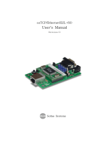
1.4.5. Ethernet Interface
EZL-50L/M has a 10Base-T Ethernet interface. It is necessary additional circuit for an
Ethernet interface. For the information of the RJ-45 with pulse-transformer, visit our
website (http://www.eztcp.com)
[EZL-50L/M Ethernet interface – TOP view]

- 12 -
1.4.6. I/O Interface
Mode
Name
Status
Description
Normal
mode
PWR
ON
Power is supplied
STS
Blinks in
every second
IP address is assigned
Repetition of HIGH/LOW for 500ms
Blinks once
after 4 times
short blinking
IP is not allocated. Repetition of
[after repetition 4 times for 150ms, HIGH
during 850ms]
ON
During TCP connection – LOW
LINK
ON
When connected to LAN – LOW
RXD
Blinks
Data are being received from LAN – HIGH
TXD
Blinks
Data are being transmitted to LAN – HIGH
P0
ON
During TCP connected– LOW
OFF
During TCP disconnected – HIGH
P1
OFF
During the EZL-50L receive data from serial
– HIGH
For interfacing RS485 chip(TXDE)
ISP
mode
PWR
ON
Power is supplied
STS
Blinks rapidly
ISP Mode – Repetition HIGH/LOW for 50ms
LINK
ON
When connected to LAN – LOW
1.4.7. Ethernet Address (MAC address)
Ethernet devices have unique 6 bytes-hardware address. The hardware address of EZL-
50L/M is set in the factory. The hardware address cannot be modified.
The address is printed in top of PCB of EZL-50L/M.
1.4.8. Hardware Flow control (RTS/CTS)
If RTS/CTS pins are set, the EZL-50L/M operates as follows:
RTS
Output
There’s are available receiving buffer of EZL-50L/M – LOW
There is no available receiving buffer of EZL-50L/M – HIGH
CTS
Input
This signal is connected to counter side device’s RTS(output port)
LOW – EZL-50L/M sends data to serial port
HIGH – EZL-50L/M doesn’t send data and wait until CTS is LOW

- 13 -
1.5. The Evaluation Board Set
The evaluation Board (EVB) is for testing with PC when user develops with EZL-
50L/M. User can test with PC if EZL-50L/M is inserted in EVB, power on with 5V
adapter, connect RS232 cable to PC, and connect Ethernet cable to hub.
1.5.1. Components
Evaluation Board
RS-232 cable
5V SMPS adapter
1.5.2. The Explanation of EVB

- 14 -
2. Installation and Test Run
2.1. Installation Method
You can install EZL-50L/M in the following steps:
Title
Item
Sub-item
Description
Checking the
communication
environment
Check items
IP address environment
3.1.
Serial port settings
3.1.
Application program to be
used
4.
Connecting to the
network
Check method
Check if LINK LED is
ON.
1.4.4.
Configuring the
environmental
variables
Configuration
method
Set by ezConfig, a utility
program for configuration
through the network.
3.2.
Set by AT commands in
ATC mode
6.
Configuration
items
IP address related items
3.1.
Serial port related items
3.1.
Communication mode
(Decided depending on
application program)
4.
Application to the field
2.1.1. Checking the Communication Environment
Before installing EZL-50L/M, check the network environment where EZL-50L/M is to
be installed, including the followings matters:
IP address environment (local IP, subnet mask, gateway, etc.)
Serial port items of the equipment to which EZL-50L/M is going to be
connected (Baud Rate, Data Bits, Parity, Stop Bit)
Application program protocol to be used (TCP Server/Client, UDP and etc.)
For application program protocol to be used, see “5. Normal mode”.
2.1.2. Connecting to the Network
Connect power to EZL-50L/M, and connect EZL-50L/M directly to the Ethernet port of

- 15 -
the PC where test is to be performed with a cross-over Ethernet cable.
2.1.3. Configuring the Environmental Variables
When network connection is completed, configure the environmental variables such as
IP address related items, serial port related items, and communication mode related
items through the LAN using “ezConfig,” the environmental variable configuration
program.
For environmental variable configuration, see “3. Setting IP Address and
Environmental Variables.”
2.2. Test
You can perform test run according to the following orders. The test run described here
is based on the assumption that the user uses EVB with EZL-50L/M and the IP address
of the PC is set to 10.1.0.2.
2.2.1. Changing PC IP Address
You can change the IP address of your PC as follows:
IP Address
10.1.0.2
Subnet Mask
255.0.0.0
Gateway IP Address
0.0.0.0
2.2.2. Installation EZL-50L/M
Connect the supplied RS232 cable between your PC and EVB, the LAN cable to the hub
to which the PC is connected or directly to the PC with a cross-over cable, and the
supplied EVB power adapter to EVB for power supply. If the LAN cable has been
correctly connected when power is supplied, LINK LED turns on.
2.2.3. Configuring EZL-50L/M
Configure EZL-50L/M setting using ezConfig, the ezTCP configuration program, as
follows.
Run ezConfig, and click [Search ezTCP] button in the ezConfig window. And, ezConfig
program will search all ezTCP on the local network.
When ezTCP is searched, MAC address of the ezTCP is displayed on the [Search List]
window (The MAC address is indicated at the bottom of the product case).

- 16 -
Select the corresponding MAC address, and set the same as shown in the following
figure and click [Write] button to save the settings.
2.2.4. Connecting to the PC Serial Port
Connect the serial port of your PC and that of EVB, using the supplied serial
communication cable. Then, run serial communication program such as Hyper Terminal
and Tera Term. When the program is run, select the same serial port values as those set
to EZL-50L/M [19,200bps, Data Bits: 8 bits, Stop Bit: 1 bit, Parity: None], which will
finish the preparation for serial communication.
2.2.5. Communication Test
When the preparation for serial communication is finished, enter the following in the
DOS window on your PC, to connect to TCP through Telnet program.
“Telnet 10.1.0.1 1470”
When TCP connection succeeds, STS LED of EVB turns ON.
When the STS LED turns ON, enter “123” on the Telnet window, and “123” will appear
on the hyper terminal. Enter “ABC” on the hyper terminal, and “ABC” will appear on
the Telnet window. Otherwise, communication test fails.

- 17 -
3. Configuring IP Address and Environmental
Variables
3.1. IP Address and Environmental Variables
For TCP/IP communication, you must set IP address related items. In addition, you have
to set serial port related items (Baud Rate, Data Bits, Parity, Flow Control and etc) to
EZL-50L/M.
You can set the IP address and the serial port related items by using ezConfig, the
supplied configuration utility which allows you to configure your EZL-50L/M over the
network, or by using AT commands in ATC mode.
Item
Description
IP Address -related
Items
Local IP Address
IP address of EZL-50L/M
Subnet Mask
Subnet Mask
Gateway IP Address
IP address of gateway
Local Port
TCP listen port number in T2S mode
Port number for waiting data in U2S
mode
Peer IP Address
IP address to connect/transmit in
COD and U2S mode
Peer Port
Port number to connect/transmit in
COD and U2S mode
Allowed IP Address
Allowed IP address in T2S mode
Serial Port
Baud Rate
1,200bps ~ 115,200bps
Data Bits
7, 8
Parity
None, Even, Odd, Mark, Space
Stop Bit
1, 2
Flow Control
NONE, RTS/CTS, XON/XOFF
Communication
Mode
Communication Mode
Set communication Mode
(T2S, ATC, COD, U2S)
Connect
/Disconnect Event
Event Byte
Minimum number of bytes attempting
to connect/transmit
Timeout
Limit time to keep connection

- 18 -
Configuration
Method Used
MAC Address Search
Enable ezConfig function.
IP Address Search
Remote configuration function with
UDP unicast
Password
ezConfig password.
ARP
Enable IP setting by ARP.
Disable TCP
Transmission Delay
Send serial data to the Ethernet with
no delay
Send MAC Address
Send the MAC address right after the
connection is established
Drop SIO RX Data
Does not send serial data which is
received before the connection
Dynamic
IP Address
DHCP
Obtain an IP Automatically from
DHCP server
PPPoE
Obtain an IP Automatically via
PPPoE
PPPoE ID & Password
ID and password to be used for
PPPoE
Local IP Address
It represents the IP address of EZL-50L/M. If you set DHCP or PPPoE is set, an IP
address is automatically allocated. So, you cannot set the local IP address.
Subnet Mask
Set subnet mask of the network where EZL-50L/M is installed
Gateway IP Address
Set the gateway IP address of the network where EZL-50L/M is installed.
Allowed IP Address
It is a permitted IP address of foreign host when EZL-50L/M operates as a server (T2S
mode). The only host that is written in this item can connect to EZL-50L/M. If Allowed
IP Address is 0.0.0.0, all hosts can connect to the EZL-50L/M.
Local Port
Port number, which is used as TCP port number waiting to be connected when EZL-

- 19 -
50L/M operates as TCP server or as the port number waiting for UDP data when it
operates in U2S mode.
Peer Port
Local port number of the server to connect when EZL-50L/M operates as TCP client or
to transmit UDP data when it operates as U2S
Baud Rate
Select a serial port speed (1,200 bps ∼ 115,200bps).
Data Bits
Select a data bit length of the serial port (7 bits or 8 bits)
Parity
Select a parity bit of the serial port (None, Even, Odd, Mark, Space).
Stop Bit
Select a stop bit length of the serial port (1 bit or 2 bits).
Flow Control
Select flow control for the serial port (None, RTS/CTS, XON/XOFF).
ezTCP Mode
Select the communication mode of EZL-50L/M (T2S, ATC, COD and U2S).
Event Byte
It decides a point of time to start connection when EZL-50L/M operates as COD. EZL-
50L/M starts to connect to the host (Peer IP Address and Peer Port) of the designated
host upon receiving as many data as specified by [Event Byte] from the serial port.
Block Size
Decide the size of UDP packet to be sent at a time when EZL-50L/M operates as U2S.
(Unit: Byte)
Timeout (Unit: second)
When EZL-50L/M operates as TCP such as T2S, COD and ATC, connection is closed if
data communication is not continued as long as the time set to this item unless this item

- 20 -
is set to 0. The maximum value is 600 seconds.
Block Interval
When EZL-50L/M operates as UDP like U2S, it transmits data in blocks by gathering
data for the time set to this item (Unit: 10ms)
MAC Address Search
You can use ezConfig utility only this item is enabled.
(If this item is not enabled, you cannot set EZL-50L/M using ezConfig. Therefore, it is
recommended to enable this all the times.)
To enable ezConfig, set this item in ISP mode.
IP Address Search
If this item is set, EZL-50L/M in other network can be configured by ezConfig. IP
Address Search function is performed in the [IP ADDRESS] tab.
Password
Set a password for configuring with ezConfig. If user forgot the password, the user can
delete the password in ISP mode.
Obtain an IP From the First Received Packet (ARP)
When this item is selected, EZL-50L/M uses the destination IP address of the first packet
coming to its MAC address as its own IP address temporarily.
Obtain an IP Automatically (DHCP)
Set to receive an IP address from DHCP server.
Obtain an IP Automatically (PPPoE)
Set to receive an IP address as PPPoE.
TX Delay
Give delay to between each data on serial port. This option is useful to serial devices that
have no buffer system or slow baud rate (delay: 200㎲, maximum baud rate 19,200bps).
Disable TCP Transmission Delay
Normally, EZL-50L/M does not send immediately after receiving data from its serial
/