Page is loading ...

Kawasaki
5
GALLONS
(18.931)
AIR
COMPRESSOR
2
PEAK
HP
COMPONENT
#691531
Kawasaki
FOR
CUSTOMER
SERVICE
1-800-590-3723
Printed
in
China
87-1904-60957
KAWASAKI™
IS
A
TRADEMARK
LICENSED
BY
KAWASAKI™
MOTORS
CORP.,
U.S.A.,
WHICH
DOES
NOT
MANUFACTURE
OR
DISTRIBUTE
THIS
PRODUCT.
CONSUMER
INQUIRES
SHOULD
BE
DIRECTED
TO:
©COPYRIGHT
2008
ALLTRADE
TOOLS
LLC
1431
VIA
PLATA
LONG
BEACH,
CA
90810-1462
USA
691531
-
5
Gallon
Air
Compressor_Rev
5/30/08
THIS
MANUAL
CONTAINS
IMPORTANT
INFORMATION
REGARDING
SAFETY,
OPERATION,
MAINTENANCE
AND
STORAGE
OF
THIS
PRODUCT
BEFORE
USE,
READ
CAREFULLY
AND
UNDERSTAND
ALL
CAUTIONS,
JJ.^NtfJGS,
INSTRUCTIONS
AND
PRODUCT
LABELS.
FAILURE
TO
DO
SO
COULD
RESULT
IN
SERIOUS
PERSONAL
INJURY
AND,™*
PROPERTY
DAMAGE.
IP
YOU
SHOULD
HAVE
ANY
QUESTIONS
OR
EXPERIENCE
A
PROBLEM
WITH
YOUR
ALLTf&DE
PRODUCT,
DO
NOT
RETURN
THIS
PRODUCT
TO
THE
STORE.
PLEASE
CALL
OUR
CUSTOMER
SERVICE
DEPAPJMENT
AT
1-800'59C3723
BEFORE
YOU
CALL.
HAVE
THE
FOLLOWING
INFORMATION
AVAILABLE:
MODEL
No.,
DAT^AJRCHASED
AND
STORr.
LCC/>T"N.
AN
ALLTRADL
REPRESENTATIVE
CAN
RESOLVE
YOUR
PROBLEM
OVER THE
PHC'.-C-
YOU
WOULD
LIKE
TO
MAKE
A
SUGGESTION
OR
COMMENT,
GIVE
US
A
CALL
OR
EMAIL
US
AT:
INFO@ALLTRADETC.;LC.UOM.
YOUF.
TtDBACK
IS
VITAL
TO
US.

TABLE OF
CONTENTS
SPECIFICATIONS
1-2
INTRODUCTION
2
SAFETY
ALERT
2
RECOGNIZE
SAFETY
SYMBOLS,
WORDS
AND
LABELS
3
UNPACKING
&
INSPECTION
3-4
SAFETY
WARNINGS
4-8
GENERAL
SAFETY
WARNINGS
4-8
INSTALLATION
AND
LOCATION
8-9
GROUNDING
INSTRUCTIONS
9-10
EXTENSION
CORDS
10-11
COMPRESSOR
FEATURES
12-14
OPERATING
THE
AIR
COMPRESSOR
14-15
MAINTENANCE
AND
CLEANING
16-17
TROUBLESHOOTING
GUIDE
18-20
PARTS
LIST
21-23
PARTS
DIAGRAM
24-25
LIMITED
WARRANTY
25-28
CONGRATULAT ONS
Thanks
for
choosing
this
product.
At
Alltrade,
our
aim
is
to
provide
you
with
quality
products
at
an
affordable
price,
and
we
want
you
to
be
totally
satisfied
with
your
product
and
our
Customer
Service.
If
any
help
and
advice
is
needed,
please
contact
us
at
1-800-590-3723.
Properly
cared
for,
this
product
will
give
you
many
years
of
satisfaction.
SPECIFICATIONS
SPECIFICATIONS
Two
Pole
Induction
Motor
3450
RPM
Power
Air
Delivery
Maximum
Pressure
Duty
Cycle
^
2.0
Peak
HP/1.1
Running
120V,
60
Hz,
15
Amps
4.7
SCFM
output
@
40
PSI
3.7
SCFM
output
@
90
PSI
125
PSI
1
75%
HP
30

TIVE(S)
HAS
BEEN
ADVISED
OF
THE
POSSIBILITY
OF
ANY
SUCH
DAMAGES.
IN
NO
EVENT,
WHETHER
AS A
RESULT
OF
A
BREACH
OF
CONTRACT,
WARRANTY,
TORT
(INCLUDING
NEGLIGENCE)
OR
OTHERWISE,
SHALL
ALLTRADE'S
AND/OR
ITS
REPRESENTATIVE(S)'
LIABILITY
EXCEED
THE
PRICE
OF
THE
AIR
COMPRESSOR.
ANY
AND
ALL
LIABILITY
CONNECTED
WITH
THE
USE
OF
THIS
AIR
COMPRESSOR
SHALL
TERMINATE
UPON
THE
EXPIRATION
OF
THE
WARRANTY
PERIODS
SPEC
IFIED
ABOVE.
Limitations
on
Warranty
Disclaimers
Some
states
do
not
allow
limitations
on
how
long
an
implied
warranty
lasts
and
some
states
do
not
allow
the exclusion
or
limitation
of
the
incidental
or
consequen
tial
damages,
so
part
or
all
of
the
above
limitations
or
exclusions
may
not
apply
to
you.
This
warranty
gives
you
specific
legal
rights,
and you
may
also
have
other
rights
which
vary
from
state
to
state.
If
your
product
is
not
covered
by
this
warranty,
please
call
our
Customer
Service
Department
at
1-800-590-3723
for
general
repair
information
and
charges.
29
SPECIFICATIONS
5
Gallon
(18.93L)
Air
Tank
Oil
Free
Direct
Drive
Pump
Thermal
Overload
Protection
for
Safety
High
Flow
Regulator
for
Precision
Air
Flow
Control
Tank
and
Outlet
Pressure
Gauges
DUTY
CYCLE:
This
air
compressor
pump
is
capable
of
running
continuously.
However,
in
order
to
pro
long
the
life
of
your
air
compressor,
it
is
recommended
that
a
50%
to
75%
average
duty
cycle
be
maintained.
Duty
cycle
refers
to
the
percentage
of
time
a
compressor
can
safe
ly
run
within
a
given
amount
of
time
expressed
as a
ratio.
Example:
Oil
lubricated
com
pressors
are
typically
rated
at
a
50%
duty
cycle,
meaning
that
the
compressor
motor
can
run
about
50%
of
the
total
time
it
is
being
used
to
supply
air
to
a
tool.
During
the
ON
time,
the
motor
is
running
to
pressurize
the
tank.
During
the
OFF
time,
the
motor
is
stopped
and
the
tools
are
running
off
on
the
pressurized
air
stored
in
the
tank.
If
your
air
tools
are
draining
pressure
off
of
the
tank
too
quickly,
the
compressor
motor
must
run
more
than
50%
of
the
time
the
compressor
is
in
use.
This
can
lead to
overheating
and
will
signifi
cantly
shorten
the
life
of
the
compressor.
INTRODUCTION
This
air
compressor
is
designed
for
Household
Use
Only
and
is
not
intended
for
commercial
applications.
It
is
well
suited
for
do-it-yourselfers
with
a
variety
of
auto
motive
and
home
uses.
This
instruction
manual
is
intended
for
your
benefit.
Please
read
and
follow
the
safe
ty,
installation,
maintenance
and
troubleshooting
steps
described
within
to
ensure
your
safety
and
satisfaction.
The
contents
of
this
instruction
manual
are
based
upon
the
latest
product
information
available
at
the
time
of
publication.
The
manufactur
er
reserves
the
right
to
make
product
changes
at
any
time
without
notice.
SAFETY
ALERT
A
WARNING
|
Rea(j
and
un(jerstand
this
entire
instruction
manual
before
attempting
to
assemble,
install,
operate
or
maintain
this
air
compres
sor.
Failure
to
comply
with
the
instructions
may
result
in
serious
personal
injury
and/or
property
damage!
SAVE
THESE
INSTRUCTIONS
FOR
FUTURE
REFERENCE.

RECOGNIZE
SAFETY
SYMBOLS,
WORDS
AND
LABELS
The
safety
instructions
provided
in
this
manual
are
not intended
to
cover
all
possible
conditions
and
practices
that
may
occur
when
operating,
maintaining
and
cleaning
power
equipment.
Always
use
common
sense
and
pay
particular
attention
to
all
the
DANGER,
WARNING,
CAUTION
and
NOTE
statements
of
this
manual.
This
is
the
safety
alert
symbol.
It
is
used
to
alert
you
to
potential
personal
injury
hazards.
Obey
all
safety
messages
that
follow
this
symbol
to
avoid
possible
injury
or
death.
A
DANGER
A
WARNING
A
CAUTION
CAUTION
NOTE
DANGER
indicates
an
imminently
hazardous
situation
which,
if
not
avoided,
will
result
in
death
or
serious
injury.
WARNING
indicates
a
potentially
hazardous
situation
which,
if
not
avoided,
could
result
in
death
or
serious
injury.
CAUTION
indicates
a
potentially
hazardous
situation
which,
if
not
avoided,
may
result
in
minor
or
moderate
injury.
CAUTION
used
without
the
safety
alert
symbol
indicates
a
potentially
hazardous
situation
which,
if
not
avoided,
may
result
in
property
damage.
NOTE
provides
additional
information
that
is
useful
for
proper
use
and
maintenance
of
this
tool.
If
a
NOTE
is
indicated
make
sure
it
is
fully
understood.
UNPACKING
&
INSPECTION
After
opening
the
carton,
unpack
your
new
air
compressor
and
related
parts
&
accessories.
Please
inspect
it
carefully
for
any
damage
that
may
have
occurred
dur
ing
transit.
Please
check
it
against
the
photograph
on
carton.
If
any
parts
are
miss
ing,
please
contact
our
Consumer
Helpline:
Phone:
1-800-590-3723
E-Mail:
The
use
of
other
than
genuine
Alltrade
Repair
Parts
will
void
warranty.
Warranty
Disclaimers
EXCLUSION
AND
DISCLAIMER
OF
ALL
OTHER
EXPRESS
WARRANTIES,
GUAR
ANTIES
AND/OR
REPRESENTATIONS.
EXCEPT
FOR
THE
LIMITED
WARRANTY
PROVIDED
ABOVE,
ALL
OTHER
EXPRESS
WARRANTIES,
GUARANTIES
AND/OR
REPRESENTATIONS
BY ALLTRADE
AND/OR
ITS
REPRESENTATIVE(S)
REGARDING
THE
DESIGN,
MANUFACTURE,
PURCHASE, USE
AND/OR
OPERATION
OF
THE
AIR
COMPRESSOR
OR
ANY
COMPONENT
THEREOF
SOLD
HEREUNDER,
REGARD
LESS
OF
WHETHER
ANY
SUCH
WARRANTY,
GUARANTY
AND/OR
REPRESENTA
TION,
WRITTEN
OR
ORAL,
ARISES
BY
OPERATION
OF
LAW
AND/OR
EQUITY
AND/OR
BY
ANY
ACT
OR
OMISSION
OF
ALLTRADE
AND/OR
ITS
REPRESENTA
TIVE^),
OR
THE
BUYER,
ARE HEREBY
EXPRESSLY
EXCLUDED
AND
DISCLAIMED
BY ALLTRADE
AND/OR
ITS
REPRESENTATIVES.
PURCHASER
KNOWINGLY
AND
WILLINGLY
WAIVES
ANY AND
ALL
SUCH
WARRANTIES
AND
RIGHTS,
CLAIMS
AND/OR
CAUSES
OF
ACTION
ARISING
THEREFROM
OR
BASED
THEREON.
PUR
CHASER'S
SOLE
AND
EXCLUSIVE
REMEDY
IS
AS
STATED
ABOVE.
EXCLUSION
AND
DISCLAIMER
OF
ALL
IMPLIED
WARRANTIES,
INCLUDING
THE
IMPLIED
WARRANTIES
OF
MERCHANTABILITY
AND
FITNESS
FOR
A
PARTICULAR
PURPOSE.
NO
WARRANTY,
ORAL
OR
WRITTEN,
OTHER
THAN
THE
ABOVE
WAR
RANTY
IS
MADE
WITH
REGARD
TO
THIS
AIR
COMPRESSOR.
ALL
EXPRESS
AND/OR
IMPLIED
WARRANTIES,
GUARANTIES
AND/OR
REPRESENTATIONS
BY
ALLTRADE
AND/OR
ITS
REPRESENTATIVE(S)
REGARDING
THE
DESIGN,
MANU
FACTURE,
PURCHASE, USE
AND/OR
OPERATION
OF
THE
AIR
COMPRESSOR
OR
ANY
COMPONENT
THEREOF
SOLD
HEREUNDER,
REGARDLESS
OF
WHETHER
ANY
SUCH
WARRANTY,
GUARANTY
AND/OR
REPRESENTATION,
WRITTEN
OR
ORAL,
ARISES
BY
OPERATION
OF
LAW
AND/OR
EQUITY
AND/OR
BY
ANY
ACT
OR
OMISSION
OF
ALLTRADE
AND/OR
ITS
REPRESENTATIVE(S),
OR
THE
PURCHAS
ER,
INCLUDING
BUT
NOT
LIMITED
TO
THE
IMPLIED
WARRANTY
OF
MER
CHANTABILITY
AND
THE
WARRANTY
OF
FITNESS
FOR
A
PARTICULAR
PURPOSE,
ARE
HEREBY
EXPRESSLY
EXCLUDED
AND
DISCLAIMED BY
ALLTRADE
AND/OR
ITS
REPRESENTATIVES.
PURCHASER
KNOWINGLY
AND
WILLINGLY
WAIVES
ANY
AND
ALL
SUCH
WARRANTIES
AND
RIGHTS,
CLAIMS
AND/OR
CAUSES
OF
ACTION
ARISING
THEREFROM
OR
BASED
THEREON.
PURCHASER'S
SOLE
AND
EXCLUSIVE
REMEDY
IS
AS
STATED
ABOVE.
Limitation
Of
Liability
IN
NO
EVENT
SHALL
ALLTRADE
AND/OR
ITS
REPRESENTATIVE(S)
BE
LIABLE
FOR
INDIRECT,
INCIDENTAL,
SPECIAL
AND/OR
CONSEQUENTIAL
DAMAGES
OF
ANY
KIND
ARISING
OUT
OF
OR
RELATED
TO,
DIRECTLY
OR
INDIRECTLY,
ANY
BREACH
OF
ANY
PROVISION OF
ANY
AGREEMENT
BETWEEN
ALLTRADE
AND/OR
ITS
REP
RESENTATIVE^)
AND
PURCHASER,
ANY
WARRANTY
HEREUNDER,
AND/OR
THE
EXISTENCE,
DESIGN,
MANUFACTURE,
PURCHASE,
USE
AND/OR
OPERATION
OF
ANY
ITEM(S)
SOLD
HEREUNDER
EVEN
IF
ALLTRADE
AND/OR
ITS
REPRESENTA-
28

ship
the
unit.
We
suggest
the
package
be
insured
against
loss
or
in
transit
damage.
When
sending
your
product
include
your
name,
address,
phone
number,
dated
proof
of
purchase
(or
copy),
and
a
statement
about
the
nature
of
problem.
Warranty
coverage
is
conditioned
upon
purchaser
furnishing
Alltrade
with
adequate
written
proof
that
they
are
the
original
purchaser
and
of
the
original
purchase
date.
Parts
returned,
freight
prepaid
and
insured,
to
Alltrade's
facility
(see
above
address)
will
be
inspected
and,
at
Alltrade's
option,
repaired
and/or
replaced
free of
charge
if
found
to
be
defective
and
subject
to
warranty.
Alltrade
retains
the
sole
discretion
to
determine
whether
any
item
or
part
is
nonconforming
and,
if
so,
whether
the
item
and/or
part
will
be
repaired
and/or
replaced.
If
Alltrade
chooses
to
replace
the
prod
uct,
it
may
replace
it
with
a
new
or
reconditioned
one
of
the
same
or
comparable
design.
The
repaired
or
replaced
unit
will
be
warranted
under
the
terms
of
the
remainder
of
applicable
warranty
period(s).
Typically,
covered
defective
parts
not
subject
to
normal
wear
and
tear
or
other
exclusions
will
be
repaired
or
replaced,
at
Alltrade's
option,
during
the
above
stated
warranty
periods.
Alltrade's
repair
and/or
replacement
of
any
nonconforming
item
and/or
part
thereof
shall
constitute
fulfill
ment
of
all
obligations
to
the
purchaser.
Alltrade
shall
not
be
responsible
or
liable
for
any
expense,
including
freight
charges,
or
repairs
made
outside
Alltrade's
facil
ity,
unless
expressly
agreed
to
by
Alltrade
in
writing.
Under
no
circumstances
shall
Alltrade
bear
any
responsibility
for
loss
of
the
unit,
loss
of
time
or
rental,
inconven
ience,
commercial
loss
or
consequential
damages.
Exclusions
This
warranty
does
not
cover
parts
damaged
due
to
normal
wear,
abnormal
condi
tions,
misapplication,
misuse,
abuse,
accidents,
operation
at
other
than
recom
mended
pressures
or
temperatures,
improper
storage
or
freight
damage.
Parts
damaged
or
worn
by
operation
in
dusty
environments
are
not
warranted.
Failure
to
follow
recommended
operating
and
maintenance
procedures
also
voids
warranty.
The
following
additional
items
are
not
covered
under
this
warranty:
pump
or
valve
failure
caused
by
rain,
excessive
humidity,
corrosive
environments
or
other
contam
inants;
cosmetic
defects
that
do
not
interfere
with
compressor
functionality;
and
rusted
tanks,
including
but
not
limited
to
rust
due
to
improper
drainage
or
corrosive
environments.
This
warranty
shall
not
apply
when:
the
air
compressor
has
been
used
for
commer
cial
or
rental
purposes;
defects
in
materials
or
workmanship
or
damages
result
from
repairs
or
alterations
which
have
been
made
or
attempted
by
others
or
the
unautho
rized
use
of
nonconforming
parts;
damage
is
due
to
abuse
(including
overloading
of
the
air
compressor
beyond
capacity),
improper
maintenance,
neglect
or
accident,
or
the
damage
is
due
to
use
of
the
air
compressor
after
partial
failure
or
use
with
improper
accessories.
Alltrade
will
not
be
liable
for
the
following:
labor
charges,
loss
or
damage
resulting
from
improper
operation,
maintenance
or
repairs
made
by
other
persons;
pre-deliv-
ery
services
such
as
assembly,
oil
or
lubricants,
and
adjustment;
maintenance
serv
ices
that
are
normally
required
to
maintain
the
air
compressor.
A
WARNING
I
do
not
operate
this
air
compressor
if
damaged
during
shipment,
handling
or
misuse.
Damage
may
result
in
bursting,
which
can
cause
serious
injury
or
property
damage.
All
damaged
parts
must
be
repaired
or
replaced
as
needed
prior
to
operating
this
air
compressor.
Check
to
see
that
all
nuts,
bolts
and
fittings
are
secure
before
putting
this
air
com
pressor
into
service.
If
you
have
any
questions,
or
require
assistance
with
damaged
or
missing
parts,
please
contact
our
Consumer
Helpline:
Phone:1-800-590-3723
E-Mail:
Please
have
the
serial
number,
model
number,
date
of
purchase,
and
parts
list
(with
missing
parts
identified)
available
for
reference
when
calling.
MODEL
NUMBER:
SERIAL
NUMBER:
DATE
OF
PURCHASE:
SAFETY
WARN
NGS
READ
ALL
SAFETY
WARNINGS
BEFORE
USING
AIR
COMPRESSOR.
GENERAL
SAFETY
WARNINGS
I
A
WARNING
I
Keep
work
area
clean.
Messy
areas
and
cluttered
workbenches
invite
person
al
injury
and/or
property
damage.
Keep
children
and
visitors
away.
All
children
should
be
kept
away
from
the
work
area.
DO
NOT
let
children
handle
the
compressor
or
extension
cord.
Maintain
a
safe
distance
for
any
person
near
the
work
area.
Operating
any
tools
or
equipment
under
the
influence
of
drugs,
alcohol,
or
medication
can
cause
personal
injury to
yourself
and
others.
Wear
proper
apparel.
Remove
your
jewelry
before
using
air
compressor.
Do
not
wear
loose
clothing,
necklaces,
rings,
bracelets,
or
other
jewelry,
which
may
get
caught
in
moving
parts.
Nonskid
footwear
and
electrically
non-conductive
gloves
are
highly
suggested
while
working.
Wear
protective
hair
covering
to
contain
long
hair.
Protect
your
eyes.
The
operation
of
any
air
compressor
can
result
in
foreign
objects
being
thrown
into
the
eyes,
which
can
result
in
severe
eye
damage.
Always
wear
eye
protection
that
meets
ANSI
Z28.1
specifications
during
air
compressor
operation.
Eyeglasses
are
not
always
safety
glasses.

1
A
WARNING
Be
responsible
for
your
hearing.
Wear
hearing
protection
during
extended
periods
of
operation.
Use
the
right
tool.
Use
tools
properly
and
for
their
intended
task.
Do
not
force
a
small
tool
to
do
the
job
of
a
heavy-duty
tool.
Using
the
right
tool
to
do
the
right
job
will
make
doing
the job
safer.
Check
damaged
parts
before
use
of
any
air
tools
or
attachments.
A
guard
or
other
part
that
is
damaged
should
be
carefully
checked
to
ensure
that
it
will
operate
properly
and
perform
its
intended
function.
Check
for
misalignment
or
binding
of
moving
parts,
breakage
of parts,
mounting,
or
any
other
conditions
that
may
affect
tool
operation.
A
guard
or
other
part that
is
damaged
should
be
properly
replaced.
See
replacement
parts
list
for
additional
details.
Avoid
unintentional
starting.
Be
sure
that
your
air
compressor
is
in
the
OFF
position
before
plugging
it
into
a
power
cord
or
electrical
receptacle.
Store
all
maintenance
tools
away
from
the
immediate
area
before
turning
ON
your
air
compressor.
Do
not
overreach.
Proper
footing
and
balance
is
a
must
at
all
times
while
using
tools.
Unstable
support
may
lead to
personal
injury
Do
not
stand
on
the
tool.
Serious
injury
could
result
if
the
tool
tips
over
or
you
accidentally
contact
tool.
Never
leave
the
air
compressor
running
unattended.
Always
turn
the
power
to
the
OFF
position
and
do
not
leave
the
air
compressor
until
it
comes
to
a
complete
stop.
When
using
air
accessories,
consult
the
owner's
manual
provided
by
the
manufacturer.
The
use
of
improper
accessories
may
cause
risk
of
injury
to
yourself
and
others.
Always
make
sure
the
tool
is
in
the
OFF
position
and
unplugged
from
the
electrical
receptacle
when
making
adjustments,
changing
parts,
or
perform
ing
any
maintenance.
Secure
work.
When
possible,
the
use
of
clamps
or
a
holding
device
is
much
safer
than
holding
the
work
piece
with
your
hands.
Keep
protective
guards
in
place
and
in
proper
working
condition.
Maintain
tools
and
equipment
with
care.
They
will
function
better
and
more
safely
when
kept
clean
and
in
good
working
condition.
Keeping
the
air
compres
sor
clean,
dry,
and
free
of
grime
will
add
to
its
life
and
performance.
Childproof
the
workshop.
The
use
of
master
switches
and
padlocks
is
highly
recommended.
Remove
starter
keys
where
applicable.
1
YEAR
LIMITED
WARRANTY
ALLTRADE
TOOLS
LLC
AIR
COMPRESSORS
Express
and
Exclusive
Limited
Warranty
to
Original
Retail
Buyer
Alltrade
Tools
LLC
(hereinafter
"Alltrade")
expressly
warrants
to
the
original
retail
purchaser
of
the
accompanying
air
compressor
and
no
one
else
all
parts
of
the
product
(except
those
parts
referred
to
below which
are
specifically
excluded
from
such
warranty
(see
Exclusions))
to
be
free
from
defects
in
materials
and
workman
ship
during
the
following
periods
from
the
original
date
of
purchase:
For
one
(1)
year
from
the
date
of
purchase:
•
Compressor
Pump
•
Tank
assembly
•
Plumbing
For
six
(6)
months
from
date
of
original
purchase:
•
Pressure
Switch
•
Regulator
•
Pilot
Valve
•
Check
Valve
•
Copper/Stainless
Steel
Line
For
ninety (90)
days
from
the
original
date
of
purchase:
•
Pressure
Gauge
•
Safety
Release
Valves
•
Drain
Valve
•
Quick
Couplers
For
thirty
(30)
days
from
the
original
date
of
purchase:
•
Air
Accessories
The
date
of
purchase
shall
be
the
date
of
shipment
to
the
original
purchaser,
or
the
date
the
original
purchaser
took
possession,
custody
or
control
of
the
product,
whichever
occurred
first.
This
warranty
shall
be
null
and
void
if
the
product
or
any
component
thereof
is
modified
or
altered.
This
warranty
does
not
apply
to
any
other
product
and/or
component
thereof
manufactured
or
distributed
by
Alltrade,
and
does
not
apply
to
products
and/or
components
thereof
designed,
manufactured
and/or
assembled
by
others,
for
which
Alltrade
makes
no
warranties
whatsoever.
THERE
ARE
NO
WARRANTIES
WHICH
EXTEND
BEYOND
THE
DESCRIPTION
ON
THE
FACE
HEREOF.
Warranty
Performance
By
purchasing
the
product,
purchaser
expressly
acknowledges
and
agrees
that
their
sole
and
exclusive
remedy
under
this
warranty
shall
be
strictly
limited
to
the
repair
or
replacement
of
any
covered
nonconforming
items
or
parts
thereof
provided
that
any
such
nonconforming
item
and/or
part
is
promptly
returned
to
Alltrade's
facility
postage
pre-paid
and
insured
(ADDRESS:
ALLTRADE
Warranty
Claims
&
Repair,
1431
Via
Plata,
Long
Beach,
CA
90810,
Attn:
Customer
Service
(TELEPHONE:
1-
800-590-3723.)
within
the
applicable
warranty
period,
with
a
written
request
by
pur
chaser
that
Alltrade
repair
and/or
replace
the
nonconforming
item
and/or
part.
We
recommend
that
you
keep
the
original
product
packaging
in
the
event
you
need
to
26

PARTS
DIAGRAM
25
A
WARNING
Some
dust
created
by
spraying,
blowing,
power
sanding,
sawing,
grinding,
drilling
and
other
construction
activities
contains
chemicals
known
to
the
State
of
California
to
cause
cancer,
birth
defects
or
other
reproductive
harm.
Reduce
your
exposure
to
these
chemicals
by
wearing
approved
safety
equip
ment
such
as
dust
masks
that
are
designed
to
filter
out
microscopic
particles.
Use
of
this
product
will
expose
you
to
chemicals
known
to
the
State
of
California
to
cause
cancer,
birth
defects,
and
reproductive
harm.
AVOID
INHAL
ING
VAPORS
AND
DUST.
WASH
HANDS
AFTER
USING.
This
product
contains
chemicals,
including
lead,
known
to
the
State
of
California to
cause
cancer,
birth
defects,
and
reproductive
harm.
WASH
HANDS
AFTER
HANDLING.
WARNING:
This
product
contains
chemicals
known
to
the
State
of California to
cause
cancer
and
birth
defects or
other
reproductive
harm.
A
WARNING
DRAIN
LIQUID
FROM
AIR
TANK
DAILY
•
Use
the
drain
valve
located
on
the
bottom
of
the
lower
air
tank
to
drain.
Failure
to
properly
drain
liquid
from
the
tank
will
cause
rust
from
moisture
buildup,
which
weakens
the
tank
and
could
lead
to
a
violent
tank
explosion.
Periodically
inspect
the
tanks
for
unsafe
conditions
such
as
corrosion,
cracked
welds,
and
leaks.
•
Release
air
slowly
when
draining
moisture
or
depressurizing
the
air
compres
sor.
Fast
moving
air
will stir
up
dust,
dirt
and
debris
that
may
be
harmful.
RISK
OF
FIRE
OR
EXPLOSION
Avoid
dangerous
environments.
Do
not
spray
combustible/flammable
liquid
in
a
confined
area.
Spray
area
must
be
well
ventilated.
Do
not
smoke
while
spray
ing
or
spray
where
spark
or
flame
is
present.
Arcing
parts
—
keep
compressor
at
least
20
feet
(6.1
m) away
from
spraying
area
and
all
explosive
vapors.
Do
not
use
compressor
near
gasoline
or
other
flammable
materials.
Operate
the
air
compressor
in
a
well-ventilated
area.
Do
not
direct
paint
or
other
spray
materi
al
towards
the
compressor.
Read
and
follow
all
safety
instructions
for
the
mate
rial
you
are
spraying.
Be
sure
to
use an
approved
respirator
designed
for
use
with
your
specific
application.
RISK
OF
INJURY
Do
not
direct
air
stream
at
body.
Use
eye
protection.
Compressor
starts
auto
matically.
Do
not
touch
MOVING
PARTS.
Keep
guards
in
place.
Compressor
does
not
supply
breathable
air.

A
DANGER
^^^^^^^^M
RISK
OF
BURSTING
•
Do
not
adjust
regulator
to
result
in
output
pressure
greater
than
marked
max
imum
pressure
of
attachment.
If
a
regulator
has
not
been
installed,
use
only
attachment
rated
at
200
PSI
or
higher.
Do
not
weld
on
or
repair
tank
—
A
DAMAGED
TANK
MUST
BE
REPLACED
IMMEDIATELY.
Do
not
operate
without
proper
safety
valve
in
place.
•
Never
attempt
to
repair
or
make
modifications
to
the
tank
or
its
attachments.
Welding,
drilling,
or
any
other
modifications
may
weaken
the
tank,
which
may
result
in
damage
from
rupture
or
explosion.
Never
remove
or
attempt
to
adjust the
pressure
switch,
safety
valve,
or other
components
that
control
tank
pressure.
Never
substitute parts
or
attempt
to
alter
the
factory
set
operating
pressures.
RISK
OF
ELECTRICAL
SHOCK
Disconnect
air
compressor
from
power
source
before
servicing.
USE
PROPERLY
grounded
ELECTRICAL
CONNECTIONS
—
do
not
use
grounding
adapters.
Do
not
use
in
wet
or
damp
locations
or
expose
to
rain.
Keep
all
connections
dry
and
off
the
ground.
Do
not
allow
power
cords
to
come
into
contact
with
water.
Do
not
touch
the
plug
with
wet
hands.
Do
not
pull
on
the
electrical
cord
to
disconnect
from
the
power
outlet.
Store
air
compressor
indoors
when
not
in
use.
Any
electrical
wiring
or
repairs
performed
on
this
air
compressor
should
be
done
by
authorized
service
personnel
in
accordance
with
federal
and
local
electrical
codes.
A
WARNING
RISK
TO
BREATHING
•
This
air
compressor
is
not
designed,
nor
intended
for
the
supply
of
breathable
quality
air.
Air
produced
by
this
unit
may
contain
carbon
monoxide
or
other
toxic
vapors.
Do
not
inhale
air
from
the
compressor
or
from
a
breathing
device
connected
to
it.
•
Operate
the
air
compressor
in
a
well-ventilated
area.
Read
and
follow
all
safe
ty
instructions
for
the
material
you
are
spraying.
Be
sure
to
use
an
approved
respirator
designed
for
use
with
your
specific
application.
RISK
OF
BURNS
Touching
exposed
metal
such
as
the
compressor
head
or
exhaust
tube
can
result
in
serious
burns.
Keep
hands
and
fingers
away
from
exposed
metal
parts
on
air
compressor
during
or
immediately
after
operation.
Air
compressors
gen
erate
significant
heat
during
normal
operation
and
will
remain
hot
for
some
time
after
use.
Do
not
reach
around
protective
shrouds
or
attempt
any
maintenance
until
compressor
has
been
allowed
to
cool.
PARTS
DIAGRAM
31
27
40
41
32
33
34
35
36
39 37
26
20
""■■■■■■•■21
22
24

PARTS
LIST
NO.
49
50
51
52
53
54
55
56
57
58
59
60
61
62
63
64
65
66
67
68
69
70
71
72
73
PART
NO.
691531-49
691531-50
691531-51
691531-52
691531-53
691531-54
691531-55
691531-56
691531-57
691531-58
691531-59
691531-60
691531-61
691531-62
691531-63
691531-64
691531-65
691531-66
691531-67
691531-68
691531-69
691531-70
691531-71
691531-72
691531-73
DESCRIPTION
Plug
Gauge
Quick
Coupler
Power
Cord
Pressure
Switch
Release
Pipe
Exhaust
Pipe
Nut
Ferrules
Elbow
Handle
Grip
Manifold
Safety
Valve
Nut
Bolt
Panel
Discharge
Pipe
Washer
Foot
Pad
Washer
Screw
Check
Valve
Tank
2.5
gallon
X2
Drain
Valve
Control
Panel
Trim
QTY
3
2
2
1
1
1
1
4
4
1
1
1
1
10
7
1
1
4
4
4
4
1
1
1
1
A
WARNING
RISK
OF
FLYING
OBJECTS
Do
not
direct
compressed
air
stream
at
people
or
pets.
The
powerful
com
pressed
air
stream
can
damage
exposed
skin
and
easily
propel
loose
dirt
and
other
small
objects
at
high-speed,
resulting
in
serious
injury.
Always
wear
eye
protection
that
meets
ANSI
Z28.1
specifications.
Use
only
OSHA
approved
air
blowguns.
Never
leave
a
pressurized
air
compressor
unattended.
Shut
OFF
air
compressor
and
relieve
pressure
before
performing
maintenance
or
repairs.
Do
not
move
the
air
compressor
while
the
air
tank
is
pressurized.
Never
attempt
to
move
the
air
compressor
by
pulling
on
the
air
hose.
RISK
OF
FALLING
Portable
air
compressors
can
fall
from
a
table,
workbench,
or
roof
causing
damage
to
the
compressor
and
could
result
in
serious
injury
or
death
to
the
operator.
Always
operate
air
compressor
in
a
stable
and
secure
position
to
pre
vent
accidental
movement
of
the
unit.
Never
operate
air
compressor
on
a
roof
or
other
elevated
position.
Use
additional
air
hose
to
reach
high
locations.
AIR
TOOLS
AND
ACCESSORIES
Do
not
exceed
the
pressure
rating of
any
air
tools,
spray guns,
air
accessories,
or
inflatables.
Excess
pressure
can
cause
them
to
explode,
resulting
in
serious
injury.
Follow
the
manufacturers
recommended
pressure
settings
for
all
air
tools
and
air
accessories.
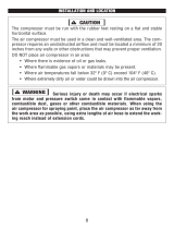
INSTALLATION
AND
LOCAT
ON
A
CAUTION
In
order
to
avoid
damaging
the
air
compressor,
do
not
allow
the
unit
to
be
tilt
ed
more
than
10°
from
the
normal
horizontal
position
when
operating.
The
compressor
must
be
run
with
the
rubber
feet
resting
on
a
flat
and
stable
horizontal
surface.
The
air
compressor
must
be
used
in
a
clean
and
well-ventilated
area.
The
com
pressor
requires
an
unobstructed
airflow
and
must
be
located
a
minimum
of
20
inches
(51cm)
from
any
walls
or
other
obstructions
that
may
prevent
proper
ventilation.

IA
CAUTION
1
DO
NOT
place
air
compressor
in
an
area:
•
Where
there
is
evidence
of
oil
or
gas
leaks.
•
Where
flammable
gas
vapors
or
materials
may
be
present.
•
Where
air
temperatures
fall
below
32°F
(0°C)
or
exceed
104°F
(40°C).
•
Where
extremely
dirty
air
or
water
could
be
drawn
into
the
air
compressor.
WARNING
Serious
injury
or
death
may
occur
if
electrical
sparks
from
motor
and
pressure
switch
come
in
contact
with
flammable
vapors,
combustible
dust,
gases
or
other
combustible
materials.
When
using
the
air
compressor
for
spraying
paint,
place
the
air
compressor
as
far
away
from
the
work
area
as
possible,
using
extra
lengths
of
air
hose
to
extend
the
work
ing
reach
instead
of
extension
cords.
GROUNDING
INSTRUCTIONS
This
product
should
be
grounded.
In
the
event
of
an
electrical
short
circuit,
ground
ing
reduces
the
risk
of
electric
shock
by
providing
an
escape
wire
for
the
electric
current.
This
product
is
equipped
with
a
cord
having
a
grounding
wire
with
an
appropriate
grounding
plug.
The
plug
must
be
plugged
into
an
outlet
that
is
prop
erly
installed
and
grounded
in
accordance
with
all
local
codes
and
ordinances.
GROUNDED
RECEPTACLE
TOOL
POWER
CORD
TAB
FOR
GROUNDING
SCREW
GROUNDING
ADAPTER
FIGURE
1.
CONNECTING
THE
AIR
COMPRESSOR
TO
THE
AC
POWER
RECEPTACLE
PARTS
LIST
NO.
25
26
27
28
29
30
31
32
33
34
35
36
37
38
39
40
41
42
43
44
45
46
47
48
PART
NO.
691531-25
691531-26
691531-27
691531-28
691531-29
691531-30
691531-31
691531-32
691531-33
691531-34
691531-35
691531-36
691531-37
691531-38
691531-39
691531-40
691531-41
691531-42
691531-43
691531-44
691531-45
691531-46
691531-47
691531-48
DESCRIPTION
Capacitor
Shroud
Cylinder
Head
Hexagon
Bolt,
M6x80
Washer,
M6
Spring
Washer,
M6
Elbow,
3/8-16x1.5
Valve
Gasket,
Top
Valve
Plate
Valve
Gasket,
Middle
Valve
Plate
Valve
Gasket.Bottom
Cylinder
Piston
Cover
Bolt,
M6x16
Piston
Ring
Rider
Ring
Circuit
Breaker
Sponge
Bolt
Washer
Air
Filter
Motor
Bolt
QTY
2
1
1
4
4
4
1
1
1
1
1
1
1
1
1
1
1
1
1
1
1
1
1
1
22

PARTS
LIST
NO.
1
2
3
4
5
6
7
8
9
10
11
12
13
14
15
16
17
18
19
20
21
22
23
24
PART
NO.
691531-1
691531-2
691531-3
691531-4
691531-5
691531-6
691531-7
691531-8
691531-9
691531-10
691531-11
691531-12
691531-13
691531-14
691531-15
691531-16
691531-17
691531-18
691531-19
691531-20
691531-21
691531-22
691531-23
691531-24
DESCRIPTION
Cooling
Fan
Bolt,
M6x16
Washer
Spring
Washer
Ball
Bearing,6203
Connected
Rod
Bolt,
M5x20
Washer,M5
Spring
Washer,M5
Crank
Crank
Case
Motor
Cover,
bottom
Bolt,
M6x16
Stator
Bolt
Washer
Ball
Bearing,6204
Rotor
Ball
Bearing,6204
Rear
Cover
Bolt,M5x90
Spring
Washer
Nut
Wave
Washer
QTY
1
1
1
1
1
1
1
1
1
1
1
1
4
1
4
4
1
1
1
1
4
4
2
2
21
A
DANGER
Improper
installation
of
the
grounding
plug
can
result
in
a
risk
of
electric
shock.
If
repair
or
replacement
of
the
cord
is
necessary,
do
not
connect
the
grounding
wire
to
either
flat
blade
terminal.
The
wire
with
GREEN
insulation
with or
without
yellow
stripes
is
the
grounding
wire.
This
product
is
for
use
on
a
nominal
120-volt
circuit
and
has a
three-prong
ground
ing
plug
that
looks
like
the
plug
illustrated
in
Figure
1.
A
temporary
adapter
sim
ilar
to
the
adapter
illustrated
in
sketch
B
(See
Page
9)
may
be
used
to
connect
this
plug
to
a
2-pole
receptacle
as
shown
in
illustration
B
when
a
properly
grounded
outlet
is
not
available.
The
temporary
adapter
shall
be
used
only
until
a
properly
grounded
outlet
(Illustration
A)
is
installed
by
a
qualified
electrician.
Tab
for
grounding
screw,
lug,
or
similar
part
extending
from
the
adapter
must
be
connect
ed
to
a
permanent
ground
such
as
a
properly
grounded
outlet
box
cover.
Whenever
the
adapter
is
used,
it
must
be
held
in
place
by
a
metal
screw.
The
use
of
a
GFCI
outlet
is
strongly
recommended.
The
third
prong
is
to
be
used
to
ground
the
tool
and
provide
protection
against
electrical
shock.
Never
remove
the
third
prong.
Check
with
a
qualified
electrician
or
serviceman
if
the
grounding
instructions
are
not
completely
understood,
or
if
in
doubt
as
to
whether
the
product
is
properly
grounded.
Do
not
modify
the
plug
provided,
if
it
will
not
fit
the
out
let,
have
the
proper
outlet
installed
by
a
qualified
electrician.
EXTENSION
CORDS
[A
CAUTION
THE
USE
OF
AN
EXTENSION
CORD
WITH
THIS
PRODUCT
IS
NOT
RECOM
MENDED
as
this
can
result
in
the
loss
of
power
to
your
air
compressor
which
can
prevent
the
motor
from
starting
or
running
properly.
This
can
also
cause
your
fuse
to
blow
or
circuit
breaker
to
trip.
Running
your
air
compressor
on
an
undersized
extension
cord
will
cause
permanent
damage
to
internal
switches
and
overheating
of
the
electric
motor.
Use
an
additional
length
of
air
hose
rather
than
an
extension
cord.
If
you
must
use
an
extension
cord,
it
should
be
plugged
into
a
GFCI
found
in
circuit
boxes
or
protected
receptacles.
Use
only
UL
listed
3-wire
extension
cords
that
have
a
3-blade
grounding
plug
and
a
3-slot
receptacle
that
will
accept
the
plug
on
the
product.
Make
sure
your
extension
cord
is
in
good
condition.
When
using
an
exten
sion
cord,
be
sure
to
use
one
heavy
enough
to
carry the
current
your
product
will
draw.
Refer
to
the
guide
on
the next
page
for
minimum
gauge
required
for
exten
sion
cords.
10

EXTENSION
CORD
LENGTH
Up
to
25
Feet
(7.6m)
26
to
50
Feet
(7.9m-15.2m)
51
to
100
Feet
(15.5m-30.5m)
WIRE
SIZE
(AWG)
12
Do
Not
Use
Do
Not
Use
Use
only
extension
cords
that
are
intended
for
outdoor
use.
These
cords
are
identi
fied
by
a
marking
"ACCEPTABLE
FOR USE
WITH
OUTDOOR
APPLIANCES,
STORE
INDOORS
WHEN
NOT
IN
USE."
Examine
extension
cord
before
use.
DO
NOT
USE
DAMAGED
EXTENSION CORDS.
Do
not
pull
on
cord
to
disconnect
from
receptacle;
always
disconnect
by
pulling
on
plug.
Keep
cord
away
from
heat
and
sharp
edges.
Always
shut
OFF
the
air
compressor
AUTO/ON
pressure
switch
before
unplugging
the
compressor.
Always
disconnect
the
extension
cord
from
the
receptacle
before
disconnecting
the
product
from
the
extension
cord.
A
WARNING
I
Avoid
electrical
shock
hazard.
Never
use
this
compres
sor
with
a
damaged
or
frayed
electrical
cord
or
extension
cord.
Inspect
all
electrical
cords
regularly.
Never
use
in
or
near
water
or
in
any
environment
where
electric
shock
is
possible.
To
reduce
the
risk
of
electrocution,
keep
all
connections
dry
and
off
the
ground.
Do
not
touch
the
plug with
wet
hands.
Guard
against
electrical
shock.
Avoid
body
contact
with
grounded
services
such
as
pipes,
ovens,
stoves,
and
refrigerator
enclosures.
If
not
properly
grounded,
this
air
compressor
can
incur
the
potential
hazard
of
light
trickle
shock,
particularly
when
used
in
damp
locations.
If
electrical
shock
occurs,
there
is
the
potential
of
second
ary
hazard
such
as
your
hands
contacting
an
operating
air
tool.
11
INSUFFICIENT
PRESSURE
AT
AIR
TOOL
OR
AIR
ACCESSORY:
PROBABLE
CAUSE:
Pressure
regulator
knob
is
not
turned
to
high
enough
pressure.
SOLUTION:
Adjust
pressure
regulator
knob
to
proper
setting.
Defective
motor/pressure
regulator
switch.
Replace.
Restricted
air
intake
filter.
Clean
or
replace
the
filter
element.
Air
leaks.
Check
for
leaks
by
applying
soap
solution
to
all
fittings
and
connections.
Bubbles
will
appear
at
leakage
points.
Tighten
or
replace
leaking
fittings
or
connections
as
needed.
Hose
or
hose
connections
are
too
small
or
long.
Replace
with
larger
hose
or
connectors.
Air
compressor
is
not
large
enough
for
air
requirement.
Check
the
accessory
air
requirement.
If
it
is
higher
than
the
CFM
or
pressure
supply
of
the
air
compressor,
you
need
a
larger
air
compressor.
MOISTURE
IN
DISCHARGE
AIR:
PROBABLE
CAUSE:
Condensation
in
air
tank
caused
by
high
level
of
atmospheric
humidity
or
air
compressor
is
not
running
long
enough.
SOLUTION:
Drain
tank
after
every
use.
Drain
air
tank
more
often
in
humid
weather
and
use
an
air
line
filter.
20

AIR
CONTINUES
TO
LEAK
AT
MOTOR/PRESSURE
SWITCH
RELEASE
VALVE
AFTER
MOTOR
STOPS:
PROBABLE
CAUSE:
SOLUTION:
Defective
pilot
valve,
the
check
Remove,
clean
or
replace.
valve
is
stuck
open.
,
,
AIR
CONTINUES
TO
LEAK AT
MOTOR/PRESSURE
SWITCH
RELEASE
VALVE
WHILE
MOTOR
IS
RUNNING:
PROBABLE
CAUSE:
SOLUTION:
Defective
motor/pressure
switch
Replace.
Check
valve
stuck
in
open
position.
Replace
check
valve.
DANGER-
Do
not
disassemble
the
check
valve
with
tank
pressurized.
Open
tank
petcock
valve
to
allow
air
to
escape
from
tank
prior
to
servicing.
AIR
LEAKS
FROM
SAFETY
RELIEF VALVE:
PROBABLE
CAUSE:
Possible
defective
safety
relief
valve.
SOLUTION:
Operate
safety
relief
valve
manually
by
pulling
on
ring.
If
it
still
leaks,
it
should
be
replaced.
Excessive
tank
pressure.
AIR
LEAKS
AT
FITTINGS:
PROBABLE
CAUSE:
Fittings
are
not
tight
enough.
Defective
motor/pressure
switch.
Replace.
SOLUTION:
Tighten
fittings
where
air
can
be
heard
escaping.
Check
fittings
with
soapy
water
solution.
DO NOT
OVERTIGHTEN.
AIR
LEAKS
IN
AIR
TANK:
PROBABLE
CAUSE:
SOLUTION:
Defective
or
rusted
air
tank.
Air
tank
must
be
replaced.
DO
NOT
ATTEMPT
TO
REPAIR
AIR
TANK!
AIR
BLOWING
FROM
INLET
FILTER:
SOLUTION:
PROBABLE
CAUSE:
Damaged
inlet
(reed)
valve.
Contact
Consumer
Helpline
at
1-800-590-3723.
19
COMPRESSOR
FEATURES
CONTROLS
AND
COMPONENTS:
1.
Automatic
On/Off
Pressure
Switch
2.
Air
Tank
Pressure
Gauge
3.
Outlet
Pressure
Gauge
4.
Dual
Air
Couplers
5.
Pressure
Regulator
6.
Safety
Relief
Valve
7.
Air
Tank
Drain
Valve
8.
Manual
Thermal
Overload
Switch
9.
Air
Intake
Filter
10.
Handle
12

COMPRESSOR
FEATURES:
1.
AUTOMATIC
ON/OFF
PRESSURE
SWITCH:
This
compressor
is
equipped
with
an
automatic
on/off
pressure
switch.
The
compressor
will
only
run
when
the
switch
is
in
the
ON/AUTO
position.
Once
the
tank
has
reached
the
desired
pre
set
pressure
("cut-out"
pressure),
the
pump
motor
will
automatically
shut
off.
While
the
switch
is
in
the
ON/AUTO
position,
the
pump
motor
will
automatically
turn
back
on
once
the
pressure
in
the
tank
drops
below
the
minimum
preset
pressure
("cut-in"
pressure).
A
WARNING
|
d0
noj
|eave
^e
compressor
unattended
while
the
power
switch
is
in
the
on/auto
position.
2.
AIR
TANK
PRESSURE
GAUGE:
The
tank
pressure
gauge
provides
a
reading
of
the
air
pressure
inside
of
the
compressor
tank.
3.
OUTLET
PRESSURE
GAUGE:
The
outlet
pressure
gauge
provides
a
reading
of
the
air
pressure
at
the
outlet
side
of
the
regulator.
This
pressure
is
controlled
by
the
pressure
regulator
and
is
always
less
than
or
equal
to
the
air
tank
pressure.
4.
DUAL
AIR
COUPLERS:
The
air
couplers
are
preinstalled
into
standard
1/4"
NPT
(F)
threads
in
the
pressure
manifold.
Use
PTFE
thread-sealing
tape
on
the
threads
to
make
sure
you
have
an
airtight
connection
when
replacing
quick
con
nect
couplers.
5.
PRESSURE
REGULATOR:
The
regulator
allows
you
to
select
the
amount
of
air
pressure
that
is
output
through
the
air
hose
into
tools
and
accessories.
Turn
the
pressure
regulator
knob
clockwise
to
increase
discharge
pressure,
and
counter
clockwise
to
decrease
discharge
pressure.
Please
refer
to
the
air
delivery
requirements
of
your
tools
for
the
proper
pressure
settings.
NOTICE:
Be
careful
not
to
overtighten
pressure
regulator
knob
when
it
"bottoms
out"
as
this
may
damage
pressure
regulator.
6.
SAFETY
RELIEF VALVE:
This
compressor
is
equipped
with
a
safety
relief
valve
that
is
designed
to
prevent
system
failures
by
relieving
pressure
from
the
system
when
the
air
pressure
reaches
a
predetermined
level.
The
safety
relief
valve
is
preset
by
the
manufacturer.
DO NOT
attempt
to
modify
or
remove
the
safety
relief
valve.
7.
AIR
TANK
DRAIN
VALVE:
Moisture
is
produced
whenever
air
is
compressed.
It
is
critical
to
drain
water
from
the
air
tank
on
this
compressor
frequently.
If
unit
is
used
only
occasionally,
tank
should
be
drained
after
each
use
and
prior
to
the
next
use.
To
drain
the
tank,
slowly
open
the
tank
drain
fitting
by
turning
counter
clockwise.
Once
all
moisture
has
drained
out,
close
the
fitting
securely.
NOTE:
Air
tank
will
not
pressurize
while
drain
valve
is
open.
13
TROUBLESHOOTING
GUIDE
THE
COMPRESSOR
DOES
NOT
START
OR
RESTART:
PROBABLE
CAUSE:
SOLUTION:
Power
cord
not
plugged
in.
Plug
cord
into
grounded
outlet.
Motor/Pressure
switch
in
OFF
position
Motor
thermal
overload
switch
has
tripped
Move
switch
to
AUTO
position.
Turn
air
compressor
off,
wait
until
the
motor
is
cool,
then
press
motor
thermal
overload
(red)
button
firmly
until
click
is
heard.
Fuse
blown
or
circuit
breaker
has
tripped.
Replace
fuse
or
reset
circuit
breaker.
Check
for
proper
fuse
amperage.
Check
for
low
voltage conditions.
Disconnect
any
other
electrical
appliances
from
circuit
or
operate
air
compressor
on
its
own
branch
circuit.
Wrong
gauge
wire or
length
of
extension
cord.
Check
chart
in
instruction
manual
for
proper
gauge
wire
and
cord
length.
Air
tank
pressure
exceeds
motor/pressure
switch
"cut-in"
pressure.
Motor
will
start
automatically
when
air
tank
pressure
drops
below
"cut-in"
pressure
of
motor/pressure
switch.
Pressure
release
valve
on
motor/pressure
switch
has
not
unloaded
pump
head
pressure.
Bleed
the
line
by
moving
the
switch
to
the
OFF
position.
Defective
motor,
motor
capacitor,
motor/pressure
switch.
Contact
Consumer
Helpline
at
1-800-590-3723
WHEN
IN
THE
START/STOP
OPTION,
MOTOR
RUNS
CONTINUOUSLY:
PROBABLE
CAUSE:
Motor/Pressure
switch
does
not
shut
off
motor
when
air
compressor
reaches
"cut-out"
pressure
and
safety
relief
valve
activates
SOLUTION:
Move
the
motor/pressure
switch
to
the
OFF
position.
If
the
motor
does
not
shut
off,
unplug
the
air
compressor.
If
the
electrical
contacts
are
welded
together,
replace
the
pressure
switch.
Air
compressor
is
incorrectly
sized.
Limit
the
air
pressure
to
the
capacity
of
the
air
compressor.
Either
use
a
smaller
tool
or
a
larger
air
compressor
18

MAINTENANCE
CHECKLIST:
Daily:
•
Drain
accumulated
liquid
from
tank.
•
Check
for
unusual
noise
and/or
vibrations.
•
Check
that
all
fasteners
are
secure.
•
Wipe
compressor
clean.
CHECKING
SAFETY
RELIEF
VALVE:
Weekly:
•
Inspect
and
clean
air
filter.
Monthly:
•
Check
for
air
leaks.
•
Check
safety
relief
valve.
A
WARNING
Safety
RELIEF
valve
must
be
replaced
if it
cannot
be
actuated or
it
leaks
air
after
the
ring
is
released.
I.The
air
compressor
must
be
turned
OFF.
2.
Disconnect
compressor
from
the
power
source.
3.
Open
tank
drain
to
bleed
off
all
air
pressure
before
attempting
any
maintenance
or
repair.
4.
Allow
compressor
to
fully
cool
before
attempting
any
maintenance
or
repair.
5.
Grasp
the
wire
ring
on
the
safety
relief
valve.
6.
Pull
and
release
the
ring
a
few
times
to
ensure
that
the
plunger
moves
in
and
out.
Replace
the
safety
relief
valve
if
plunger
does
not
move
or
is
difficult
to
move.
CHECKING
AIR
FILTER
ELEMENT:
I.The
air
compressor
must
be
turned
OFF.
2.
Disconnect
compressor
from
the
power
source.
3.
Open
tank
drain
to
bleed
off
all
air
pressure
before
attempting
any
maintenance
or
repair.
4.
Allow
compressor
to
fully
cool
before
attempting
any
maintenance
or
repair.
5.
Remove
the
face
of
the
filter
body
to
access
the
filter
element
by
removing
screw
holding
filter
in
place.
6.
Use
compressed
air
to
blow
loose
dirt
and
debris
from
the
paper
filter
element.
Replace
filter
element
if
it
cannot
be
cleaned
sufficiently.
7.
Reinsert
filter
element
into
filter
body
and
reinstall
filter
faceplate.
MOISTURE
IN
COMPRESSED
AIR
Moisture
is
a
normal
by-product
of
compressing
air.
As
the
moisture
builds
during
compressor
use,
it
can
be
carried
though
the
air
hose.
When
using
paint
spray
gun
or
sandblasting gun,
the
use
of
a
special
filter
to
remove
moisture
from
the
air
line
is
highly
recommended.
Moisture
in
the
compressed
air
will
cause
water
spots
in
paint
jobs
and
cause
blasting
media
to
clog
the
sandblasting
gun.
NOTE
A
dirty
air
filter
will
reduce
air
compressor
performance
and
can
lead
to
product
failure.
8.
MANUAL
THERMAL
OVERLOAD
SWITCH:
The
electric
motor
has
a
manual
thermal
overload
protector.
If
the
motor
overheats
for
any
reason,
the
thermal
overload
protector
will
shut
off
the
motor.
Turn
pressure
switch
to
the
"off"
position
and
wait
for
unit
to
cool
before
pushing
the
reset
button
and
restarting
the
compressor.
NOTICE:
This
air
compressor
is
designed
for
household
use
only
and
is
not
intended
to
operate
heavy-duty
air
tools.
If
your
application's
demands
exceed
the
capacity
of
this
air
compressor,
a
larger
air
compressor
that
is
matched
to
your
application
is
recommended.
If
the
unit
shuts
down
again,
please
call
the
consumer
helpline
at
1-800-590-3723
for
assistance.
9.
AIR
INTAKE
FILTER:
This
compressor
is
equipped
with
an
externally
accessible
air
intake
filter
that
is
designed
to
clean
air
coming
into
the
pump.
The
filter
element
is
easily
removed
for
periodic
cleaning.
Use
compressed
air
to
blow
loose
dirt
and
debris
from
the
paper
filter
element
and
reinstall.
Replace
filter
element
when
necessary.
10.HANDLE:
Convenient
handle
for
easy
transport.
OPERATING
THE
A
R
COMPRESSOR
INITIAL
SETUP
/
BREAK-IN
PROCEDURE:
A
CAUTION
|
do
not
attach
air
hose,
air
tools
or
other
air
accessories
to
the
air
outlet
until
break-in
procedure
has
been
successfully
completed.
1.
Read
and
understand
the
entire
instruction
manual,
including
all
safety
warn
ings
before
setting
up
air
compressor.
2.
Place
air
compressor
on
a
flat,
level
surface.
3.
Turn
the
pressure
regulator
knob
fully
clockwise
to
open
airflow
from
air
outlet
port.
NOTE
Be
careful
not
to
overtighten
pressure
regulator
knob
when
it
"bottoms
out"
as
this
may
damage
pressure
regulator.
4.
Turn
the
power
switch
to
the
OFF
position.
5.
Plug
power
cord
directly
into
a
properly
grounded
power
source
of
the
correct
voltage
(see
Grounding
Instructions
on page
9
of
this
instruction
manual).
6.
Open
the
tank
drain
valve
to
allow
air
to
escape
preventing
air
pressure
buildup
in
the
air
tank.
14

7.
Turn
the
compressor
ON
by
moving
the
switch
to
the
AUTO/ON
position
and
run
the
air
compressor
for
a
period
of
20
minutes
to
break-in
the
air
pump.
8.
With
the
compressor
still
running,
at
the
end
of
the
20-minute
break-in
period,
close
the
tank
drain
valve.
The
air
compressor
will
build
air
pressure
to
the
maximum
preset
pressure
("cut-out"
pressure)
and
automatically
shut
off.
9.
Slowly
turn
the
tank
drain
valve
to
open
airflow
from
drain
and
bleed
off
air
from
the
air
tank.
The
air
compressor
will
automatically
restart
once
the
pressure
in
the
air
tank
drops
below
the
minimum
preset
pressure
("cut-in"
pressure).
lO.Turn
the
compressor
off
by
moving
the
switch
to
the
OFF
position.
11.Release
pressure
from
the
system.
Drain
moisture
from
the
air
tank
by
slowly
opening
the
air
tank
drain
valve
by
turning
counter-clockwise.
Tilt
tank
to
remove
all
moisture.
Once
all
the
moisture
has
drained
out,
close
the
fitting
securely.
NOTE:
Air
tank
will
not
pressurize
while
drain
valve
is
open.
12.Disconnect
the
power
cord
from
the
power
outlet.
NOTE:
Make
sure
the
power
switch
is
in
the
OFF
position
when
connecting
or
disconnecting
power
cord
from
electrical
outlet.
13.Your
new
air
compressor
is
now
ready
to
use.
STARTUP:
1.
Before
each
startup,
make
sure
the
power
switch
is
in
the
OFF
position.
2.
Place
air
compressor
on
a
flat,
level
surface.
3.
Release
pressure
from
the
system.
Drain
moisture
from
the
air
tank
by
slowly
opening
the
air
tank
drain
valve
by
turning
counter-clockwise.
Once
all
the
moisture
has
drained
out,
close
the
fitting
securely.
NOTE:
Air
tank
will
not
pressurize while
drain
valve
is
open.
4.
Turn
the
pressure
regulator
knob
fully
counterclockwise
to
close
airflow
from
air
outlet
port.
5.
Attach
air
hose
and
accessories.
I
A
WARNING
|
Too
much
ajr
pressure
caUSes
a
hazardous
risk
of
bursting.
Check
the
manufacturer's
maximum
pressure
rating
for
air
tools
and
accessories.
The
regulator
outlet
pressure
must
never
exceed
the
maximum
pressure
rating.
6.
Before
connecting
the
compressor
to
the
grounded
outlet,
check
for
broken
compo
nents
and
accessories,
and
check
for
damage
to
the
hose.
7.
Plug
power
cord
directly
into
a
properly
grounded
power
source
of
the
correct
voltage
(see
Grounding
Instructions
on page
9
of
this
instruction
manual).
8.
Turn
the
compressor
ON
by
moving
the
switch
to
the
AUTO/ON
position
and
allow
the
tank
pressure
to
build.
Once
the
air
pressure
reaches
the
maximum
preset
pressure
("cut-out"
pressure)
it
will
automatically
shut
off.
9.
Slowly
turn
the
pressure
regulator
knob
clockwise
to
open
airflow
from
air
out
let
port
until
desired
output
pressure
is
reached.
NOTE:
The
air
compressor
will
automatically
restart
once
the
pressure
in
the
air
tank
drops
below
the
mini
mum
preset
pressure
("cut-in"
pressure).
MAINTENANCE
AND
CLEANING
A
WARNING
Disconnect
AIR
COMPRESSOR
from
power
source
and
bleed
off
all
air
pressure
before
attempting
any
maintenance
or
repair.
SHUTDOWN
AND
STORAGE:
NOTE:
NEVER
stop
the
air
compressor
by
unplugging
it
from
the
power
outlet
as
this
may
result
in
damage
to
the
compressor.
LTurn
the
switch
to
the
OFF
position
2.
Disconnect
the
power
cord
from
the
power
outlet.
Disconnect
the
power
cord
from
the
power
outlet
by
grabbing
the
plug
(not
the cord).
Loop
around
electric
cord
holder
for
storage.
3.
Turn
the
pressure
regulator
knob
fully
counterclockwise
to
close
airflow
from
air
outlet
port.
Check
the
outlet
pressure
gauge
to
ensure
that
it
reads
0
PSI.
4.
Remove
the
air
hose
and
any
air
accessories.
5.
Drain
moisture
from
the
air
tank
by
slowly
opening
the
air
tank
drain
valve
by
turning
counter-clockwise.
Tilt
tank
to
remove
all
moisture.
Once
all
the
mois
ture
has
drained
out,
close
the
fitting
securely.
6.
Allow
the
compressor
to
cool
down.
7.
Wipe
the
air
compressor
clean
and
store
it
in
a
clean,
dry,
and
non-freezing
location.
WHEN
PERFORMING
ANY
MAINTENANCE
OR
SERVICE:
I.The
air
compressor
must
be
turned
off.
2.
Disconnect
compressor
from
the
power
source.
3.
Open
tank
drain
to
bleed
off
all
air
pressure
before
attempting
any
maintenance
or
repair.
4.
Allow
compressor
to
fully
cool
before
attempting
any
maintenance
or
repair.
Check
the
air
compressor
frequently
for
any
visible
problems
and
follow
mainte
nance
procedures
each
time
the
compressor
is
used.
16

7.
Turn
the
compressor
ON
by
moving
the
switch
to
the
AUTO/ON
position
and
run
the
air
compressor
for
a
period
of
20
minutes
to
break-in
the
air
pump.
8.
With
the
compressor
still
running,
at
the
end
of
the
20-minute
break-in
period,
close
the
tank
drain
valve.
The
air
compressor
will
build
air
pressure
to
the
maximum
preset
pressure
("cut-out"
pressure)
and
automatically
shut
off.
9.
Slowly
turn
the
tank
drain
valve
to
open
airflow
from
drain
and
bleed
off
air
from
the
air
tank.
The
air
compressor
will
automatically
restart
once
the
pressure
in
the
air
tank
drops
below
the
minimum
preset
pressure
("cut-in"
pressure).
lO.Turn
the
compressor
off
by
moving
the
switch
to
the
OFF
position.
11.Release
pressure
from
the
system.
Drain
moisture
from
the
air
tank
by
slowly
opening
the
air
tank
drain
valve
by
turning
counter-clockwise.
Tilt
tank
to
remove
all
moisture.
Once
all
the
moisture
has
drained
out,
close
the
fitting
securely.
NOTE:
Air
tank
will
not
pressurize
while
drain
valve
is
open.
12.Disconnect
the
power
cord
from
the
power
outlet.
NOTE:
Make
sure
the
power
switch
is
in
the
OFF
position
when
connecting
or
disconnecting
power
cord
from
electrical
outlet.
13.Your
new
air
compressor
is
now
ready
to
use.
STARTUP:
1.
Before
each
startup,
make
sure
the
power
switch
is
in
the
OFF
position.
2.
Place
air
compressor
on
a
flat,
level
surface.
3.
Release
pressure
from
the
system.
Drain
moisture
from
the
air
tank
by
slowly
opening
the
air
tank
drain
valve
by
turning
counter-clockwise.
Once
all
the
moisture
has
drained
out,
close
the
fitting
securely.
NOTE:
Air
tank
will
not
pressurize while
drain
valve
is
open.
4.
Turn
the
pressure
regulator
knob
fully
counterclockwise
to
close
airflow
from
air
outlet
port.
5.
Attach
air
hose
and
accessories.
I
A
WARNING
|
Too
much
ajr
pressure
caUSes
a
hazardous
risk
of
bursting.
Check
the
manufacturer's
maximum
pressure
rating
for
air
tools
and
accessories.
The
regulator
outlet
pressure
must
never
exceed
the
maximum
pressure
rating.
6.
Before
connecting
the
compressor
to
the
grounded
outlet,
check
for
broken
compo
nents
and
accessories,
and
check
for
damage
to
the
hose.
7.
Plug
power
cord
directly
into
a
properly
grounded
power
source
of
the
correct
voltage
(see
Grounding
Instructions
on page
9
of
this
instruction
manual).
8.
Turn
the
compressor
ON
by
moving
the
switch
to
the
AUTO/ON
position
and
allow
the
tank
pressure
to
build.
Once
the
air
pressure
reaches
the
maximum
preset
pressure
("cut-out"
pressure)
it
will
automatically
shut
off.
9.
Slowly
turn
the
pressure
regulator
knob
clockwise
to
open
airflow
from
air
out
let
port
until
desired
output
pressure
is
reached.
NOTE:
The
air
compressor
will
automatically
restart
once
the
pressure
in
the
air
tank
drops
below
the
mini
mum
preset
pressure
("cut-in"
pressure).
MAINTENANCE
AND
CLEANING
A
WARNING
Disconnect
AIR
COMPRESSOR
from
power
source
and
bleed
off
all
air
pressure
before
attempting
any
maintenance
or
repair.
SHUTDOWN
AND
STORAGE:
NOTE:
NEVER
stop
the
air
compressor
by
unplugging
it
from
the
power
outlet
as
this
may
result
in
damage
to
the
compressor.
LTurn
the
switch
to
the
OFF
position
2.
Disconnect
the
power
cord
from
the
power
outlet.
Disconnect
the
power
cord
from
the
power
outlet
by
grabbing
the
plug
(not
the cord).
Loop
around
electric
cord
holder
for
storage.
3.
Turn
the
pressure
regulator
knob
fully
counterclockwise
to
close
airflow
from
air
outlet
port.
Check
the
outlet
pressure
gauge
to
ensure
that
it
reads
0
PSI.
4.
Remove
the
air
hose
and
any
air
accessories.
5.
Drain
moisture
from
the
air
tank
by
slowly
opening
the
air
tank
drain
valve
by
turning
counter-clockwise.
Tilt
tank
to
remove
all
moisture.
Once
all
the
mois
ture
has
drained
out,
close
the
fitting
securely.
6.
Allow
the
compressor
to
cool
down.
7.
Wipe
the
air
compressor
clean
and
store
it
in
a
clean,
dry,
and
non-freezing
location.
WHEN
PERFORMING
ANY
MAINTENANCE
OR
SERVICE:
I.The
air
compressor
must
be
turned
off.
2.
Disconnect
compressor
from
the
power
source.
3.
Open
tank
drain
to
bleed
off
all
air
pressure
before
attempting
any
maintenance
or
repair.
4.
Allow
compressor
to
fully
cool
before
attempting
any
maintenance
or
repair.
Check
the
air
compressor
frequently
for
any
visible
problems
and
follow
mainte
nance
procedures
each
time
the
compressor
is
used.
16

MAINTENANCE
CHECKLIST:
Daily:
•
Drain
accumulated
liquid
from
tank.
•
Check
for
unusual
noise
and/or
vibrations.
•
Check
that
all
fasteners
are
secure.
•
Wipe
compressor
clean.
CHECKING
SAFETY
RELIEF
VALVE:
Weekly:
•
Inspect
and
clean
air
filter.
Monthly:
•
Check
for
air
leaks.
•
Check
safety
relief
valve.
A
WARNING
Safety
RELIEF
valve
must
be
replaced
if it
cannot
be
actuated or
it
leaks
air
after
the
ring
is
released.
I.The
air
compressor
must
be
turned
OFF.
2.
Disconnect
compressor
from
the
power
source.
3.
Open
tank
drain
to
bleed
off
all
air
pressure
before
attempting
any
maintenance
or
repair.
4.
Allow
compressor
to
fully
cool
before
attempting
any
maintenance
or
repair.
5.
Grasp
the
wire
ring
on
the
safety
relief
valve.
6.
Pull
and
release
the
ring
a
few
times
to
ensure
that
the
plunger
moves
in
and
out.
Replace
the
safety
relief
valve
if
plunger
does
not
move
or
is
difficult
to
move.
CHECKING
AIR
FILTER
ELEMENT:
I.The
air
compressor
must
be
turned
OFF.
2.
Disconnect
compressor
from
the
power
source.
3.
Open
tank
drain
to
bleed
off
all
air
pressure
before
attempting
any
maintenance
or
repair.
4.
Allow
compressor
to
fully
cool
before
attempting
any
maintenance
or
repair.
5.
Remove
the
face
of
the
filter
body
to
access
the
filter
element
by
removing
screw
holding
filter
in
place.
6.
Use
compressed
air
to
blow
loose
dirt
and
debris
from
the
paper
filter
element.
Replace
filter
element
if
it
cannot
be
cleaned
sufficiently.
7.
Reinsert
filter
element
into
filter
body
and
reinstall
filter
faceplate.
MOISTURE
IN
COMPRESSED
AIR
Moisture
is
a
normal
by-product
of
compressing
air.
As
the
moisture
builds
during
compressor
use,
it
can
be
carried
though
the
air
hose.
When
using
paint
spray
gun
or
sandblasting gun,
the
use
of
a
special
filter
to
remove
moisture
from
the
air
line
is
highly
recommended.
Moisture
in
the
compressed
air
will
cause
water
spots
in
paint
jobs
and
cause
blasting
media
to
clog
the
sandblasting
gun.
NOTE
A
dirty
air
filter
will
reduce
air
compressor
performance
and
can
lead
to
product
failure.
8.
MANUAL
THERMAL
OVERLOAD
SWITCH:
The
electric
motor
has
a
manual
thermal
overload
protector.
If
the
motor
overheats
for
any
reason,
the
thermal
overload
protector
will
shut
off
the
motor.
Turn
pressure
switch
to
the
"off"
position
and
wait
for
unit
to
cool
before
pushing
the
reset
button
and
restarting
the
compressor.
NOTICE:
This
air
compressor
is
designed
for
household
use
only
and
is
not
intended
to
operate
heavy-duty
air
tools.
If
your
application's
demands
exceed
the
capacity
of
this
air
compressor,
a
larger
air
compressor
that
is
matched
to
your
application
is
recommended.
If
the
unit
shuts
down
again,
please
call
the
consumer
helpline
at
1-800-590-3723
for
assistance.
9.
AIR
INTAKE
FILTER:
This
compressor
is
equipped
with
an
externally
accessible
air
intake
filter
that
is
designed
to
clean
air
coming
into
the
pump.
The
filter
element
is
easily
removed
for
periodic
cleaning.
Use
compressed
air
to
blow
loose
dirt
and
debris
from
the
paper
filter
element
and
reinstall.
Replace
filter
element
when
necessary.
10.HANDLE:
Convenient
handle
for
easy
transport.
OPERATING
THE
A
R
COMPRESSOR
INITIAL
SETUP
/
BREAK-IN
PROCEDURE:
A
CAUTION
|
do
not
attach
air
hose,
air
tools
or
other
air
accessories
to
the
air
outlet
until
break-in
procedure
has
been
successfully
completed.
1.
Read
and
understand
the
entire
instruction
manual,
including
all
safety
warn
ings
before
setting
up
air
compressor.
2.
Place
air
compressor
on
a
flat,
level
surface.
3.
Turn
the
pressure
regulator
knob
fully
clockwise
to
open
airflow
from
air
outlet
port.
NOTE
Be
careful
not
to
overtighten
pressure
regulator
knob
when
it
"bottoms
out"
as
this
may
damage
pressure
regulator.
4.
Turn
the
power
switch
to
the
OFF
position.
5.
Plug
power
cord
directly
into
a
properly
grounded
power
source
of
the
correct
voltage
(see
Grounding
Instructions
on page
9
of
this
instruction
manual).
6.
Open
the
tank
drain
valve
to
allow
air
to
escape
preventing
air
pressure
buildup
in
the
air
tank.
14

COMPRESSOR
FEATURES:
1.
AUTOMATIC
ON/OFF
PRESSURE
SWITCH:
This
compressor
is
equipped
with
an
automatic
on/off
pressure
switch.
The
compressor
will
only
run
when
the
switch
is
in
the
ON/AUTO
position.
Once
the
tank
has
reached
the
desired
pre
set
pressure
("cut-out"
pressure),
the
pump
motor
will
automatically
shut
off.
While
the
switch
is
in
the
ON/AUTO
position,
the
pump
motor
will
automatically
turn
back
on
once
the
pressure
in
the
tank
drops
below
the
minimum
preset
pressure
("cut-in"
pressure).
A
WARNING
|
d0
noj
|eave
^e
compressor
unattended
while
the
power
switch
is
in
the
on/auto
position.
2.
AIR
TANK
PRESSURE
GAUGE:
The
tank
pressure
gauge
provides
a
reading
of
the
air
pressure
inside
of
the
compressor
tank.
3.
OUTLET
PRESSURE
GAUGE:
The
outlet
pressure
gauge
provides
a
reading
of
the
air
pressure
at
the
outlet
side
of
the
regulator.
This
pressure
is
controlled
by
the
pressure
regulator
and
is
always
less
than
or
equal
to
the
air
tank
pressure.
4.
DUAL
AIR
COUPLERS:
The
air
couplers
are
preinstalled
into
standard
1/4"
NPT
(F)
threads
in
the
pressure
manifold.
Use
PTFE
thread-sealing
tape
on
the
threads
to
make
sure
you
have
an
airtight
connection
when
replacing
quick
con
nect
couplers.
5.
PRESSURE
REGULATOR:
The
regulator
allows
you
to
select
the
amount
of
air
pressure
that
is
output
through
the
air
hose
into
tools
and
accessories.
Turn
the
pressure
regulator
knob
clockwise
to
increase
discharge
pressure,
and
counter
clockwise
to
decrease
discharge
pressure.
Please
refer
to
the
air
delivery
requirements
of
your
tools
for
the
proper
pressure
settings.
NOTICE:
Be
careful
not
to
overtighten
pressure
regulator
knob
when
it
"bottoms
out"
as
this
may
damage
pressure
regulator.
6.
SAFETY
RELIEF VALVE:
This
compressor
is
equipped
with
a
safety
relief
valve
that
is
designed
to
prevent
system
failures
by
relieving
pressure
from
the
system
when
the
air
pressure
reaches
a
predetermined
level.
The
safety
relief
valve
is
preset
by
the
manufacturer.
DO NOT
attempt
to
modify
or
remove
the
safety
relief
valve.
7.
AIR
TANK
DRAIN
VALVE:
Moisture
is
produced
whenever
air
is
compressed.
It
is
critical
to
drain
water
from
the
air
tank
on
this
compressor
frequently.
If
unit
is
used
only
occasionally,
tank
should
be
drained
after
each
use
and
prior
to
the
next
use.
To
drain
the
tank,
slowly
open
the
tank
drain
fitting
by
turning
counter
clockwise.
Once
all
moisture
has
drained
out,
close
the
fitting
securely.
NOTE:
Air
tank
will
not
pressurize
while
drain
valve
is
open.
13
TROUBLESHOOTING
GUIDE
THE
COMPRESSOR
DOES
NOT
START
OR
RESTART:
PROBABLE
CAUSE:
SOLUTION:
Power
cord
not
plugged
in.
Plug
cord
into
grounded
outlet.
Motor/Pressure
switch
in
OFF
position
Motor
thermal
overload
switch
has
tripped
Move
switch
to
AUTO
position.
Turn
air
compressor
off,
wait
until
the
motor
is
cool,
then
press
motor
thermal
overload
(red)
button
firmly
until
click
is
heard.
Fuse
blown
or
circuit
breaker
has
tripped.
Replace
fuse
or
reset
circuit
breaker.
Check
for
proper
fuse
amperage.
Check
for
low
voltage conditions.
Disconnect
any
other
electrical
appliances
from
circuit
or
operate
air
compressor
on
its
own
branch
circuit.
Wrong
gauge
wire or
length
of
extension
cord.
Check
chart
in
instruction
manual
for
proper
gauge
wire
and
cord
length.
Air
tank
pressure
exceeds
motor/pressure
switch
"cut-in"
pressure.
Motor
will
start
automatically
when
air
tank
pressure
drops
below
"cut-in"
pressure
of
motor/pressure
switch.
Pressure
release
valve
on
motor/pressure
switch
has
not
unloaded
pump
head
pressure.
Bleed
the
line
by
moving
the
switch
to
the
OFF
position.
Defective
motor,
motor
capacitor,
motor/pressure
switch.
Contact
Consumer
Helpline
at
1-800-590-3723
WHEN
IN
THE
START/STOP
OPTION,
MOTOR
RUNS
CONTINUOUSLY:
PROBABLE
CAUSE:
Motor/Pressure
switch
does
not
shut
off
motor
when
air
compressor
reaches
"cut-out"
pressure
and
safety
relief
valve
activates
SOLUTION:
Move
the
motor/pressure
switch
to
the
OFF
position.
If
the
motor
does
not
shut
off,
unplug
the
air
compressor.
If
the
electrical
contacts
are
welded
together,
replace
the
pressure
switch.
Air
compressor
is
incorrectly
sized.
Limit
the
air
pressure
to
the
capacity
of
the
air
compressor.
Either
use
a
smaller
tool
or
a
larger
air
compressor
18

AIR
CONTINUES
TO
LEAK
AT
MOTOR/PRESSURE
SWITCH
RELEASE
VALVE
AFTER
MOTOR
STOPS:
PROBABLE
CAUSE:
SOLUTION:
Defective
pilot
valve,
the
check
Remove,
clean
or
replace.
valve
is
stuck
open.
,
,
AIR
CONTINUES
TO
LEAK AT
MOTOR/PRESSURE
SWITCH
RELEASE
VALVE
WHILE
MOTOR
IS
RUNNING:
PROBABLE
CAUSE:
SOLUTION:
Defective
motor/pressure
switch
Replace.
Check
valve
stuck
in
open
position.
Replace
check
valve.
DANGER-
Do
not
disassemble
the
check
valve
with
tank
pressurized.
Open
tank
petcock
valve
to
allow
air
to
escape
from
tank
prior
to
servicing.
AIR
LEAKS
FROM
SAFETY
RELIEF VALVE:
PROBABLE
CAUSE:
Possible
defective
safety
relief
valve.
SOLUTION:
Operate
safety
relief
valve
manually
by
pulling
on
ring.
If
it
still
leaks,
it
should
be
replaced.
Excessive
tank
pressure.
AIR
LEAKS
AT
FITTINGS:
PROBABLE
CAUSE:
Fittings
are
not
tight
enough.
Defective
motor/pressure
switch.
Replace.
SOLUTION:
Tighten
fittings
where
air
can
be
heard
escaping.
Check
fittings
with
soapy
water
solution.
DO NOT
OVERTIGHTEN.
AIR
LEAKS
IN
AIR
TANK:
PROBABLE
CAUSE:
SOLUTION:
Defective
or
rusted
air
tank.
Air
tank
must
be
replaced.
DO
NOT
ATTEMPT
TO
REPAIR
AIR
TANK!
AIR
BLOWING
FROM
INLET
FILTER:
SOLUTION:
PROBABLE
CAUSE:
Damaged
inlet
(reed)
valve.
Contact
Consumer
Helpline
at
1-800-590-3723.
19
COMPRESSOR
FEATURES
CONTROLS
AND
COMPONENTS:
1.
Automatic
On/Off
Pressure
Switch
2.
Air
Tank
Pressure
Gauge
3.
Outlet
Pressure
Gauge
4.
Dual
Air
Couplers
5.
Pressure
Regulator
6.
Safety
Relief
Valve
7.
Air
Tank
Drain
Valve
8.
Manual
Thermal
Overload
Switch
9.
Air
Intake
Filter
10.
Handle
12
/