Page is loading ...

P/N: 2300-0551
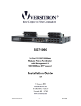
Quick Installation Guide
Gigabit Managed Switch
Model No.: SP6524A / SP6524F
6
7
Hardware Installation
Connecting to the Console Port and Ethernet Port
Attach one end of the supplied RS-232 cable to PC or
terminal and the other end to the console port of the
SP6524A/SP6524F front panel. The connected terminal or
PC must support the terminal emulation program.
Connect one end of an RJ-45 cable to the Ethernet port at
the front panel and the other end to PC or terminal for web
interface management.
Cabling Requirements for 1000Base-SX/LX SFP Module
SP6524A/SP6524F is more complex and comprehensive
contrast TP cabling in the fiber media. Basically, there are two
categories of fiber, multimode and single mode. The later is
categorized into several classes by the distance supported.
They are SX, LX, LHX, XD and ZX. Form the viewpoint of
connector type, there mainly are LC and Bi-Di LC.
Gigabit Fiber with multimode LC SFP module
Gigabit Fiber with single-mode LC SFP module
Gigabit Fiber with Bi-Di LC 1310nm SFP module
Gigabit Fiber with Bi-Di LC 1550nm SFP module
Note : SP6524A/SP6524F only supports the SFP module from
the following venders:
1. Micronet Communications
2. Finisar Corporation
3. AVAGO Technologies
4. Agilient Technologies
For more details, please refer to user manual.
•
•
•
•
•
•
•
1.
1.
1.
1.
5
Configuration
Web-based User Interface
Before using web management, install the SP6524A/SP6524F
on the network and make sure that any one of the PCs on the
network can connect with the SP6524A/SP6524F through the
web browser. The default IP, subnet mask, username and
password are as follows:IP
Address: 192.168.1.1
Subnet Mask: 255.255.255.0
User Name: admin
Password: admin
Login in the Console Interface
When the connection between SP6524A/SP6524F and PC is
ready, turn on the PC and run a terminal emulation program or
Hyper Terminal and configure its communication parameters to
match the following default characteristics of the console port:
Baud Rate: 115200 bps
Data Bits: 8
Parity: none
Stop Bit: 1
After finishing the parameter settings, click "OK". When the
blank screen shows up, press Enter key to bring out the login
prompt. Key in the "admin" (default value) for the both User
name and Password (use Enter key to switch), then press
Enter key and the command line interface of console
management appears.
----------For more details, please refer to user manual.--------
IP
IP
IP
IP
IP
IP
IP
IP
CE Mark Warning
This equipment complies with the requirements relating to
electromagnetic compatibility of the essential protection
requirement of Council Directive 89/336/EEC on the
approximation of the laws of the Member States. Company
has an on-going policy of upgrading its products and it may be
possible that information in this document is not up-to-date.
Please check with your local distributors for the latest
information. No part of this document can be copied or
reproduced in any form without written consent from the
company.
Web: www.micronet.com.tw ; www.micronet.info

4
1 2
Introduction
Micronet SP6524A /SP6524F Gigabit Managed Switch delivers
wire speed Gigabit performance and rich layer 2 management
functions, suitable for high performance workgroups and server
applications. With 10/100/1000Mbps RJ-45 ports and shared
mini-GBIC slots for fiber optic connection, it provides a perfect
solution for huge data transmission and preserves the great
flexibility of network infrastructure.
Package Contents
Before you start installing the device, verify the following items
are in the package:
SP6524A /SP6524F Managed Switch
Quick Installation Guide
Manual CD
RS-232 cable
Mounting accessory
Power Cord
•
•
•
•
•
•
3
Physical Description
SP6524F front view
SP6524F rear view
RESET Button:
It is used to reset the management system.
Key Features
Compliant with IEEE802.3 10Base-T, IEEE802.3u 100Base-
TX, IEEE802.3ab 1000Base-T, and IEEE802.3z 1000Base-
LX/SX standards.
SP6524A provide 24 RJ-45 ports of 10/100/1000Mbps and 4
shared mini-GBIC slots for fiber extension
SP6524F provide 8 combo SFP/RJ-45 ports and 16 SFP slots
for fiber extension
Support IEEE 802.3ad Link Aggregation, up to 12 trunk
groups, up to 16 ports for each group
Support IEEE802.1q tag-based VLAN, IEEE 802.1q-in-q
nested VLAN, and IEEE802.1p traffic prioritization (CoS)
Support traffic classification based on user-defined priority or
information in MAC, IP, and TCP/UDP header
Support ingress and egress bandwidth control with a
resolution of 1Mbps
Support broadcast / multicast / unknown unicast storm control
Support jumbo frame up to 9216K bytes
Support 802.1d STP, 802.1w Rapid STP, IEEE802.1s MSTP
Support 802.1x port-based authentication and port security
with MAC address
Support IGMP snooping including active and passive mode
Support Virtual Stacking Management for 16 devices stacking
Support MIBs: Interface MIB, Address Translation MIB,
RMON MIB, IP MIB, ICMP MIB, TCP MIB, UDP MIB, SNMP
MIB, MIB-II, Bridge MIB, Ethernet MIB, Enterprise MIB
•
•
•
•
•
•
•
•
•
•
•
•
•
•
•
•
•
•
•
•
•
•
•
•
•
SP6524A front view
SP6524A rear view
LED Definition:
LED Status Operation
POWER
Power is on
On/Green
10/100/1000M Ethernet TP Port SP6524F (1 to 8)
or SP6524A(1 to 24) LED
Link detected
Traffic detected
Traffic detected
1000M link detected
100M link detected
10M or no link detected
1000Base-SX/LX Gigabit Fiber Port SP6524F
(1 to 24) or SP6524A(21to 24) LED
Link detected
Link detected
Link detected
LINK/ACT
On/Green
Blink/Green
Off
10/100/1000
Mbps
On/Green
Blink/Green
Off
SFP
(LINK/ACT)
On/Green
Blink/Green
Off
/