Page is loading ...

RFBA & RFBA Plus User Manual Crown Broadcast Page 1
RF Broadcast Appliance Family
User Manual
Applicable Models:
RFBA – AM/FM/NOAA Weather Band/Public Service Band Triple Receiver and FM MPX Translator
RFBA Plus – AM/FM/NOAA Weather Band/Public Service Band Triple Receiver, FM MPX Translator, and
AM/FM/NOAA Weather Band/Public Service Band Triple Modulation Monitor
Document Revision History:
V0.9 27APR2012 CHT Preliminary Release
V1.03 30APR2012 CHT Release
V1.04 25JUN2012 CHT Update for Public Service Band
V1.05 19NOV2012 CHT Typos Fixed and Updated for Firmware 1.04
V1.10 19MAR2013 CHT Updated for Firmware 1.10
V1.20 8JUL2014 CHT Updated for Firmware 1.20, SNMP, AF Lists

RFBA & RFBA Plus User Manual Crown Broadcast Page 2
Table of Contents
Table of Figures ............................................................................................................................................. 4
Getting Started .............................................................................................................................................. 5
Model Numbers ............................................................................................................................................ 6
Installation and Configurations ..................................................................................................................... 6
Triple Tuner for EAS/CAP Reception ......................................................................................................... 6
Triple Tuner Modulation Monitor ............................................................................................................ 7
Standalone FM Translator with RDS Encoding ......................................................................................... 7
Stand-alone Automatic Stereo Separation (SASS) ................................................................................ 7
Mixed Combination of Other Configurations ........................................................................................... 8
System Overview .......................................................................................................................................... 8
Functionality ............................................................................................................................................. 8
Block Diagram ............................................................................................................................................... 8
Front Panel .................................................................................................................................................... 9
User Interface ........................................................................................................................................... 9
Tuner Setup Menu .............................................................................................................................. 11
Tuner Monitor Menu .......................................................................................................................... 13
MPX Setup Menu ................................................................................................................................ 16
Network Setup Menu .......................................................................................................................... 19
System Setup Menu ............................................................................................................................ 20
Front Panel Lock Out ........................................................................................................................... 22
Web Server.................................................................................................................................................. 23
User Interface ......................................................................................................................................... 23
Appliance Home ...................................................................................................................................... 23
Receiver Status ........................................................................................................................................ 24
Modulation Analyzer............................................................................................................................... 25
Device Setup ........................................................................................................................................... 26
Contact Info ......................................................................................................................................... 35
SNMP (Simple Network Management Protocol) Server ............................................................................. 35
User Interface ......................................................................................................................................... 35
Product Specifications................................................................................................................................. 36
Software Updates ....................................................................................................................................... 37

RFBA & RFBA Plus User Manual Crown Broadcast Page 3
USB flash drive requirements ............................................................................................................. 37
FCC / IC Compliance .................................................................................................................................... 38
Class A Product: .................................................................................................................................. 38
Class B Product: ................................................................................................................................... 38
Contact Information .................................................................................................................................... 39
Crown Broadcast ..................................................................................................................................... 39
Sales .................................................................................................................................................... 39
Service ................................................................................................................................................. 39

RFBA & RFBA Plus User Manual Crown Broadcast Page 4
Table of Figures
Figure 1 - Front View ..................................................................................................................................... 5
Figure 2 - Rear Views .................................................................................................................................... 5
Figure 3 - Phoenix 20-Pin photo (The RFBA uses the 16-pin version of this connector) .............................. 5
Figure 4 - Pin-out ........................................................................................................................................... 6
Figure 5 - Block Diagram ............................................................................................................................... 9
Figure 6 - Main Menu .................................................................................................................................. 10
Figure 7 - Navigation Menu Overview ........................................................................................................ 10
Figure 8 - Tuner Setup Menu ...................................................................................................................... 11
Figure 9 - Audio Level Conversions ............................................................................................................. 13
Figure 10 - Tuner Monitor Menu ................................................................................................................ 14
Figure 11 - MPX Setup Menu ...................................................................................................................... 17
Figure 12 - Network Setup Menu ................................................................................................................ 19
Figure 13 - System Menu ............................................................................................................................ 20
Figure 14 - Relay Codes ............................................................................................................................... 22
Figure 15 - Web Server Navigation Menu ................................................................................................... 23
Figure 16 - Appliance Home ........................................................................................................................ 24
Figure 17 - Receiver Status.......................................................................................................................... 25
Figure 18 - Modulation Analyzer................................................................................................................. 26
Figure 19 - Device Setup -> Receivers ......................................................................................................... 27
Figure 20 - Device Setup -> MPX Output .................................................................................................... 28
Figure 21 - Device Setup -> Alerts ............................................................................................................... 30
Figure 22 - Device Setup -> Network -> IPV4 .............................................................................................. 31
Figure 23 - Device Setup -> Network -> SMTP ............................................................................................ 32
Figure 24 - Device Setup -> Network -> SNMP ........................................................................................... 33
Figure 25 - Device Setup -> System ............................................................................................................. 34
Figure 26 - Contact Info .............................................................................................................................. 35
Figure 27 - Specifications ............................................................................................................................ 37

RFBA & RFBA Plus User Manual Crown Broadcast Page 5
Getting Started
The front panel of your RFBA family of Broadcast Appliances has a 40x2 character LCD display and a
navigation style button that are shown in FIGURE 1. The user is able to adjust most of the settings of the
RFBA unit by navigating through the display’s menu with the front panel buttons. Some of the advanced
features are only available via the Ethernet connection.
The rear of the RFBA is shown in FIGURE 2. The RFBA includes communication connections for Ethernet
and USB, BNC connectors for each tuner input, and one BNC connector for an FM MPX output. The
Phoenix-style connector provides analog audio output from each tuner and a relay output for
configurable alerts. The power jack is used to power the RFBA unit via the included power supply at
12Volts, 1 Amp. Please note that not all power supplies are created equal. The power supply that ships
with the RFBA was specifically selected for its noise performance in the bands of interest.
Figure 1 - Front View
Figure 2 - Rear Views
The Phoenix connector mating part number is “FMCD 1.5/8-ST-3.5” and the order number is 1738869.
FIGURE 3 shows the 20-pin version of the connector for the RFBA. One mating connector is provided with
the purchase of each RFBA.
Figure 3 - Phoenix 20-Pin photo (The RFBA uses the 16-pin version of this connector)
The pin-out for the RFBA is shown in FIGURE 4. The first pin is located closest to the power supply
connector, and is numbered right to left when viewed from the rear of the product. A silkscreen is also

RFBA & RFBA Plus User Manual Crown Broadcast Page 6
provided on the rear of the unit for quick reference. Connections to the connector are made by using a
small screwdriver to push in on the orange portion of the connector while inserting your stripped cable
into the corresponding hole.
Top Row
Description
Description
Bottom Row
Top #1
Tuner 3- Left - / Relay-P1
Tuner 3- Right - / Relay-P2
Bottom #1
Top #2
Ground
Reserved
Bottom #2
Top #3
Tuner 3- Left +
Tuner 3- Right +
Bottom #3
Top #4
Tuner 2- Left -
Tuner 2- Right -
Bottom #4
Top #5
Tuner 2- Left +
Tuner 2- Right +
Bottom #5
Top #6
Ground
Ground
Bottom #6
Top #7
Tuner 1- Left -
Tuner 1- Right -
Bottom #7
Top #8
Tuner 1- Left +
Tuner 1- Right +
Bottom #8
Figure 4 - Pin-out
Model Numbers
Currently, there are two models in the RFBA family available: The RFBA and the RFBA Plus. Both units
will be labeled as “RFBA” on the front panel
The RFBA Plus contains every feature of the RFBA, but also adds the ability to operate as a highly
accurate DSP-Based Triple Tuner Modulation Monitor. Every RFBA unit can be upgraded to be an RFBA
Plus via a user-installable software key. If you are interested in upgrading your RFBA unit to the full
capabilities of the RFBA Plus, please contact Crown Broadcast for sales and demo information.
Installation and Configurations
Your RFBA is versatile and designed to handle many user configurations. The typical configurations
for the RFBA are: Triple Tuner for EAS/CAP, Triple Tuner Modulation Monitor, Standalone FM
Translator with RDS Encoding, or a Mixed Combination of Other Configurations.
Triple Tuner for EAS/CAP Reception
This all-in-one product allows the user to monitor three separate broadcasts while outputting the audio
to a stand-alone EAS/CAP decoder unit. By separating the tuners from the EAS/CAP decoder, the user
can be assured that the sensitivity of the tuners is not compromised by the harsh EMC noise that is
typically seen in the PC-based EAS/CAP decoder units. In this configuration, the audio signals from the
Phoenix connector may be connected directly to the EAS/CAP decoder unit. The audio level for each
tuner may be digitally adjusted to meet the voltage requirements of your particular EAS/CAP decoder.
The RFBA includes capability for Hi-Jack Avoidance and Squelch functions; in this configuration, users
will typically disable these features. The Hi-Jack and Squelch functions can be adjusted via the front
panel setup menus or via the Ethernet connection.

RFBA & RFBA Plus User Manual Crown Broadcast Page 7
Triple Tuner Modulation Monitor
The RFBA is capable of monitoring over 20 FM signal parameters as well as RDS data for each tuner
simultaneously. The end user may wish to monitor several of their own stations to assure proper
functionality or they may wish to monitor adjacent channels that sometimes over-modulate. The RFBA
can also be controlled via the Ethernet connection (Web Pages or SNMP), allowing a remote user to
switch between stations that are being monitored. For operation in this configuration, the only
connections required are the RF antennas and, if remote monitoring is desired, Ethernet. All of the
parameters are available via the display menu or via the Ethernet connection. Note: the modulation
monitor feature is only available on the RFBA Plus or as an upgrade to the RFBA. All units are capable of
performing modulation monitor functionality. If your RFBA does not include this function, please
contact Crown Broadcast for sales and demo information.
Standalone FM Translator with RDS Encoding
The RFBA uses a Digital Signal Processor, or DSP, to reconstruct an FM Stereo Composite Signal. In
addition to the typical composite signal, the RFBA can also add RDS data to the composite signal. The
audio source for this configuration is only available from the main tuner (Tuner #1). Tuner #2 and Tuner
#3 do not include capability for composite signal regeneration, but can still be used for signal reception
or analyzing.
The FM Stereo Composite Signal is always available from Tuner #1. In contrast to older translator
designs, the RFBA does not simply pass through a down-converted FM multiplex. Instead, the audio and
RDS data are recovered using world-class automotive-grade reception algorithms customized for
translator purposes. A new FM multiplex with optional RDS data is then created digitally. The composite
output signal is available on the BNC connector on the rear of the product, and can be fed to the
composite input of your RF modulator/transmitter. The user can digitally adjust the MPX output level,
pilot percentage, RDS modulation level, and many RDS parameters. Your RFBA will automatically adjust
the audio portions of the FM Multiplex to account for user adjustments of the Pilot level and of the RDS
level, ensuring strict adherence to the composite level specifications of the FCC.
The user can program many of the RDS parameters to be passed through from the received signal or to
be user defined, allowing for certain data to be unique to your translator location. Program
Identification (PID) is an example of an RDS parameter that the end user may wish to program
differently, while leaving Program Service Name (PSName) and other fields unmodified.
Stand-alone Automatic Stereo Separation (SASS)
The FM translator also includes a new function to align the composite output with a specific RF
modulator. Many RF modulators include a filter on the MPX input. This filter can cause a small shift in
the L-R component of the composite signal and will degrade the maximum stereo separation. The RFBA
includes an alignment routine where the RFBA can adjust the L-R for your specific RF modulator thus
optimizing the maximum separation. Please see the Sass Alignment section of this manual for further
details.

RFBA & RFBA Plus User Manual Crown Broadcast Page 8
Mixed Combination of Other Configurations
The RFBA is capable of performing many of the above configurations concurrently. Tuner #1 is always
able to receive a broadcast station and output audio. It is also always able to reconstruct an FM
composite signal from the station received. If the modulation monitor option is installed, it can also do
a full analysis of the signal received on Tuner #1.
System Overview
The RF Broadcast Appliance (RFBA) has been designed to perform multiple functions. The RFBA includes
three independent automotive-grade DSP-based receivers. Each receiver is capable of receiving AM,
FM, NOAA Weather band or Public Service frequencies. This makes the RFBA desirable for meeting the
broadcasters EAS needs of monitoring of multiple stations. The RFBA also incorporates a DSP based FM
composite generator that can be used for FM translators. The FM composite generator has additional
functionality to add RDS capability to your translated signal, acting in a RDS pass thru mode or a user
programmable mode. The RFBA can also be used as a triple tuner modulation monitor and RDS
decoder. Band and frequency selection is performed by front panel user control or remote Ethernet
control.
Functionality
The onboard AM/FM receiver utilizes a Digital Signal Processor (DSP) that incorporates advanced
algorithms to provide world-class receiver performance. Tuner parameters have been optimized by
experts in AM/FM reception to provide the best overall performance for this specific product,
eliminating the need for broadcasters to make adjustments. The receiver is capable of tuning:
1) FM frequencies from 76.00 – 108.00 MHz in steps of 0.05 MHz (50 kHz)
2) AM frequencies from 520 – 1710 kHz in 10 kHz increments
3) AM frequencies from 531 – 1629 kHz in 9 kHz increments
4) All NOAA weather band channels from 162.400 – 162.550 MHz (Channels 1 – 7)
5) Public Service band from 144.000 – 175.000 MHz in 5 kHz increments
Block Diagram
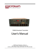
A high level block diagram of the RFBA is shown in FIGURE 5. As described previously, this product
contains three independent tuners. Each tuner is capable of receiving AM, FM, NOAA Weather band or
Public Service band. Each tuner has its own BNC RF connector. The right and left audio signals for each
tuner are available as differential outputs on the supplied Phoenix connector. The audio outputs of
tuner #1 are also used by the onboard DSP to generate a FM composite signal that can be used for
translators. The onboard DSP also uses an RDS encoder so the user can add RDS information to the
translator output. The FM composite output is available via a BNC connector on the rear of the product.
Tuner #3 has an option to have a differential or single-ended audio output for the right and left
channels. In the single-ended mode the negative outputs are used as connections to an internal relay.
The relay can be programmed via the display or Ethernet to open or close based on certain events, such

RFBA & RFBA Plus User Manual Crown Broadcast Page 9
as squelch or Hi-Jack. The default configuration for Tuner #3 is single ended audio with the internal
relay.
Figure 5 - Block Diagram
Front Panel
User Interface
The RFBA includes a 2 x 40 character LCD and a navigation-style button that allows the user to adjust
most settings and monitor most available parameters. The navigation control has up, down, left, right,
and enter buttons. Long-pressing the up or down button will auto-increment/-decrement the current
field until the button is released. Some of the more advanced features of the RFBA are only accessible
via the Ethernet interface, though these features are generally only applicable when Ethernet is
TUNER 1
Audio
DSP
Left+
Left-
BNC
Composite Out
Micro
40 x 2 LCD Display
RDS
Encoder
USB
Ethernet
Right+
Right-
BNC
TUNER#1
TUNER 2
Left+
Left-
Right+
Right-
BNC
TUNER#2
TUNER 3
Left+
Left-
Right+
Right-
BNC
TUNER#3
Button
Relay

RFBA & RFBA Plus User Manual Crown Broadcast Page 10
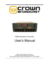
connected. The display incorporates arrows allow menu navigation. Upon product initialization, the
RFBA will display, for each tuner, the currently tuned frequency and one other parameter that is
configured in each tuner’s setup menu as “Main Meter.” FIGURE 6 shows an example main screen. The
RFBA will also default to this main screen after a defined period of inactivity, if the user has configured
the “Screen Timeout” option under the System menu.
9
8
.
1
M
H
z
S
t
1
0
8
0
k
H
z
1
6
2
.
4
7
5
M
H
z
R
S
S
I
█
█
█
█
█
█
▎
R
S
S
I
█
█
█
█
█
█
▎
R
S
S
I
█
█
█
█
█
█
▎
Figure 6 - Main Menu
The overall menu navigation map is shown below:
Figure 7 - Navigation Menu Overview
Main
Tuner 1
Setup
Band
Frequency
Frequency #2
Auto Squelch
Squelch Level
RSSI Alert
De Emphasis
Main Meter
PPM
threshold
PPM Holdoff
Hi-jack
Avoidance
Hi-jack PID
RX PID
Mono/
Stereo
Bandwidth
Audio Level
Tuner 1
Monitor
RSSI dBuV
RSSI bar
graph
RDS
• PID
• PSNAME
• PTY
• PTYN
• UTC Time
• UTC Offset
• Local Time
• Local Date
• TP
• TA
• MS
• DI
Modulation
Analyzer
• Pilot Level
• RDS Level
• SCA 67 kHz
• SCA 92 kHz
• Peaks/Minute
• Modulation
• Deviation
Positvie
• Deviation
Negative
• Audio Left
• Audio Right
• Audio L+R
• Audio L-R
• AM Noise
• Multipath
Tuner 2
Setup
Band
Frequency
Frequency #2
Auto Squelch
Squelch Level
RSSI Alert
De Emphasis
Main Meter
PPM
threshold
PPM Holdoff
Hi-jack
Avoidance
Hi-jack PID
RX PID
Mono/
Stereo
Bandwidth
Audio Level
Tuner 2
Monitor
RSSI dBuV
RSSI bar
graph
RDS
• PID
• PSNAME
• PTY
• PTYN
• UTC Time
• UTC Offset
• Local Time
• Local Date
• TP
• TA
• MS
• DI
Modulation
Analyzer
• Pilot Level
• RDS Level
• SCA 67 kHz
• SCA 92 kHz
• Peaks/Minute
• Modulation
• Deviation
Positvie
• Deviation
Negative
• Audio Left
• Audio Right
• Audio L+R
• Audio L-R
• AM Noise
• Multipath
Tuner 3
Setup
Band
Frequency
Frequency #2
Auto Squelch
Squelch Level
RSSI Alert
De Emphasis
Main Meter
PPM
threshold
PPM Holdoff
Hi-jack
Avoidance
Hi-jack PID
RX PID
Mono/
Stereo
Bandwidth
Audio Level
Tuner 3
Monitor
RSSI dBuV
RSSI bar
graph
RDS
• PID
• PSNAME
• PTY
• PTYN
• UTC Time
• UTC Offset
• Local Time
• Local Date
• TP
• TA
• MS
• DI
Modulation
Analyzer
• Pilot Level
• RDS Level
• SCA 67 kHz
• SCA 92 kHz
• Peaks/Minute
• Modulation
• Deviation
Positvie
• Deviation
Negative
• Audio Left
• Audio Right
• Audio L+R
• Audio L-R
• AM Noise
• Multipath
MPX Setup
MPX Level
Pilot Level
RDS Settings
• RDS State
• RDS Level
• PID SOURCE
• USER PID
• PSNAME
SOURCE
• USER
PSNAME
• PTY SOURCE
• USER PTY
• TP SOURCE
• USER TP
• TA SOURCE
• USER TA
• MS SOURCE
• USER MS
• DI SOURCE
• USER DI
• CT SOURCE
• RT SOURCE
SASS
Aligment
SASS
Separation
Network
Setup
IP
SUBNET
GATEWAY
MAC
System
Setup
Model
Number
Serial
Number
Firmware
version
Region
Software
reset
Restore
Factory
Defaults
Relay
Screen
Timeout
Screen
Autolock
Modulation
Analyzer Key

RFBA & RFBA Plus User Manual Crown Broadcast Page 11
Tuner Setup Menu
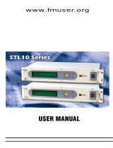
Each tuner has a separate menu and can be controlled independently. The menu structure for all tuners
are identical thus the following descriptions are relevant for all three tuners. A description of each of
the setup features is detailed below:
R
X
1
:
S
E
T
U
P
→
B
A
N
D
:
F
M
R
S
S
I
:
5
5
d
B
µ
V
F
R
E
Q
:
1
0
1
.
7
M
H
z
F
R
E
Q
-
D
U
A
L
:
N
/
A
A
U
T
O
S
Q
U
E
L
C
H
:
D
i
s
a
b
l
e
d
S
Q
U
E
L
C
H
L
E
V
E
L
:
4
d
B
µ
V
R
S
S
I
A
L
E
R
T
L
V
L
:
1
1
d
B
µ
V
D
E
-
E
M
P
H
A
S
I
S
:
7
5
µ
S
e
C
M
A
I
N
M
E
T
E
R
:
R
S
S
I
P
P
M
T
H
R
E
S
H
O
L
D
1
1
2
%
P
P
M
H
O
L
D
O
F
F
5
m
s
H
I
-
J
A
C
K
A
V
O
I
D
A
N
C
E
:
O
F
F
H
I
-
J
A
C
K
P
I
D
:
0
x
1
F
3
E
R
E
C
E
I
V
E
D
P
I
D
:
0
x
1
F
3
E
M
O
N
O
/
S
T
E
R
E
O
:
S
T
E
R
E
O
B
A
N
D
W
I
D
T
H
:
A
U
T
O
A
U
D
I
O
L
E
V
E
L
:
+
0
.
4
d
B
V
Figure 8 - Tuner Setup Menu
Band: The user can select the broadcast band to receive. Each tuner is capable of receiving AM,
FM, NOAA Weather band, Dual NOAA Weather band and Public Service band. The dual NOAA
weather band feature allows the user to receive two NOAA weather band channels on one tuner.
In the dual band receiver mode, frequency #1 audio is output to the left channel and frequency
#2 audio is output to the right channel. Dual NOAA weather band mode requires a software key
to enable the feature.
Frequency:
This menu allows the user to program the received frequency for each band.
The channel spacing and band limits are determined based on the band and region settings.
Frequency dual: This menu is only used in the dual NOAA weather band mode. This menu allows
tuning of the second frequency for this tuner. Recall that the audio output of frequency #2 will only
be available on the right channel while the audio for frequency #1 will be available on the left
channel, and this feature requires a software key to enable the option.
Auto Squelch: This menu item will allow the audio levels to be squelched when the RSSI level is
below a particular threshold. For Tuner #1, the MPX composite level will also be squelched. During
Dual NOAA Weather band operation, the squelch will only trigger on the first frequency selected,
and not on frequency #2.
Squelch Level:
This control allows the user to determine the RSSI level where the audio squelch
will occur. This control has units of dBµV in 1dB steps. If the received RSSI level drops below the

RFBA & RFBA Plus User Manual Crown Broadcast Page 12
currently set squelch control level, the audio outputs will mute. If this occurs on Tuner #1, the MPX
output of the receiver will also mute, keeping a transmitter equipped with a silence detector from
broadcasting “dead air.” The RFBA will automatically un-mute the audio (and MPX output for Tuner
#1) when the input RSSI level is more than 6dB above the currently-set squelch control level. Email
alerts, if configured, will be sent whenever the unit is squelched or un-squelched. The email alert
must be properly configured in the Ethernet interface for this to function correctly.
RSSI Alert Level: This control allows the user to determine the RSSI level at which an email alert
will be sent out. If the email alerts are not set properly then the email alerts will not be received.
This control has units of dBµV in 1dB steps. This setting has no effect on the audio or MPX output
levels. This feature is useful for a station engineer to monitor a change in the receive antenna which
might require adjusting.
De Emphasis:
This
setting allows control of the receiver de-emphasis. Options are OFF, 50
µ
sec or 75 µsec. Available options will vary by Region and tuner number.
Main Meter: This allows the user to determine which bar graph to be displayed on the main
menu, if any. If the modulation analyzer is not available, then the user may only select RSSI or OFF
for Tuners 2 and 3, or may only choose RSSI, MOD, or OFF for Tuner 1.
PPM Threshold: This allows control of the peaks per minute readings in the “Peaks/Minute”
section of the modulation analyzer. The user can adjust the percentage modulation trigger
threshold in which the PPM counter will start counting. The nominal setting for this control is
105%.
PPM Holdoff: This allows control of the peaks per minute readings in the “Peaks/Minute” section
of the modulation analyzer. The user can adjust the time in which the PPM counter can re-trigger
for an over modulation event. The nominal setting for this control is 5 mSec.
Hi-jack Avoidance: This menu item will allow the user to monitor the received RDS PID and
perform user selectable tasks if the RDS PID is not received or is invalid. This is useful when a rogue
station is broadcasting on your frequency. Email alerts will be sent whenever the unit is hijacked or
un-hijacked. Note: the email alert must be properly configured via the Ethernet interface for this to
function correctly.
Hi-jack PID: This setting allows the user to program the desired PID to be monitoring on the
received frequency.
Received PID:
This
value is a visual aid of the currently tuned station PID. It is intended to
assist t
he user while setting the Hi-jack PID. This value cannot be adjusted.
Mono/Stereo: This allows the user to force the receiver to mono or stereo reception. This is
useful under very weak signal conditions where stereo reception produces undesirable levels of
noise. When setting the signal to mono on tuner #1 the MPX output will also output a mono
signal (L+R only). RDS will still be encoded if it is turned on, however.

RFBA User Manual Crown Broadcast Page 13
Bandwidth: This allows the user to program the receiver IF bandwidth. The allowed settings are
“AUTO” or “WIDE”. The receivers used in the RFBA are state of the art DSP based receivers and in
most conditions the AUTO setting is highly recommended. If the primary use of a specific receiver is
as a modulation analyzer, then the WIDE setting will give the most accurate results.
Volume Level: This allows the user to adjust the audio output levels on the Phoenix connector. The
user can adjust the output level in 0.1 dB steps. The default setting is 0 dBV, which is equivalent to
1 V
RMS
into a 600 ohm load single ended. The signal is twice that level if using the differential
signals. The user can select between +10dBV and -40dBV. The volume level should not be set
above +3.0dBV for a received station broadcasting 75 kHz deviation. Exceeding that level will start
to cause distortion in the output audio. If using a single ended configuration, use the + outputs and
GND as the audio reference. In FIGURE 9, conversions from dBV to V
rms
and V
pk-pk
are included for
reference. Note that the V
rms
and V
pk-pk
are actually twice that level when using the differential
signals.
dBV
3.0
2.5
2.0
1.5
1.0
0.5
0.0
-0.5
-1.0
-1.5
-2.0
-2.5
-3.0
-3.5
V
rms
1.413
1.334
1.259
1.189
1.122
1.059
1.000
0.944
0.891
0.841
0.794
0.750
0.708
0.668
V
pk-pk
3.995
3.772
3.561
3.362
3.174
2.996
2.828
2.670
2.521
2.380
2.247
2.121
2.002
1.890
dBV
-3.5
-4.0
-4.5
-5.0
-5.5
-6.0
-6.5
-7.0
-7.5
-8.0
-8.5
-9.0
-9.5
-10.0
V
rms
0.668
0.631
0.596
0.562
0.531
0.501
0.473
0.447
0.422
0.398
0.376
0.355
0.335
0.316
V
pk-pk
1.890
1.785
1.685
1.591
1.502
1.418
1.338
1.263
1.193
1.126
1.063
1.004
0.947
0.894
Figure 9 - Audio Level Conversions
Tuner Monitor Menu
Each tuner has a separate monitor menu and can be viewed independently. While in the monitor
menu the user is not allowed to modify any of the tuner setup parameters, only viewing of the
received parameters are allowed. The menu structure for all tuners are identical thus the following
descriptions is relevant for all three tuners. A description of each of the monitor features is detailed
below:

RFBA & RFBA Plus User Manual Crown Broadcast Page 14
R
X
1
:
M
O
N
I
T
O
R
R
S
S
I
:
5
5
d
B
µ
V
1
0
5
.
1
M
H
z
S
t
→
R
S
S
I
:
█
█
█
█
█
█
█
█
█
█
█
█
█
▎
R
D
S
P
I
D
:
0
x
1
2
C
4
R
D
S
P
S
N
A
M
E
:
W
A
B
C
R
D
S
P
T
Y
:
C
O
U
N
T
R
Y
R
D
S
P
T
Y
N
:
B
A
S
E
B
A
L
L
R
D
S
U
T
C
T
I
M
E
:
1
9
:
5
3
R
D
S
U
T
C
O
F
F
S
E
T
:
-
0
5
:
0
0
R
D
S
L
O
C
A
L
T
I
M
E
:
1
4
:
5
3
R
D
S
D
A
T
E
(
M
D
Y
)
0
3
/
1
5
/
1
2
R
D
S
T
P
:
1
R
D
S
T
A
:
1
R
D
S
M
S
:
M
U
S
I
C
R
D
S
D
I
:
0
P
I
L
O
T
L
E
V
E
L
:
9
.
0
%
R
D
S
L
E
V
E
L
:
6
.
0
%
S
C
A
6
7
K
H
z
L
E
V
E
L
:
3
.
0
%
S
C
A
9
2
K
H
z
L
E
V
E
L
:
3
.
0
%
S
C
A
L
E
V
E
L
:
1
.
2
3
5
V
r
m
s
P
E
A
K
S
/
M
I
N
U
T
E
:
1
2
9
M
O
D
:
█
█
█
█
█
█
█
█
█
▎
▏
1
0
3
%
D
E
V
+
:
█
█
█
█
█
█
█
▎
▏
1
0
2
k
z
D
E
V
-
:
█
█
█
█
█
█
█
█
█
▎
▏
8
2
k
z
L
E
F
T
:
█
█
█
█
█
█
█
▎
▏
1
0
3
%
R
G
H
T
:
█
█
█
█
█
█
█
█
█
▎
▏
1
0
3
%
L
+
R
:
█
█
█
█
█
█
█
█
█
▎
▏
+
2
d
B
L
-
R
:
█
█
█
█
█
█
█
█
▏
-
3
5
d
B
A
M
N
:
█
▎
▏
4
%
M
P
T
H
:
█
█
█
█
▏
2
0
%
Figure 10 - Tuner Monitor Menu
RSSI dBµV: This is the Received Signal Strength Indicator and is displayed in units of dB
relative to 1µV at the antenna input. The RSSI range is valid from 0 dBµV to 65 dBµV.
RSSI:
This is the Received Signal Strength Indicator bar graph and gives a visual
indication of the RSSI amplitude. Maximum scale is 65 dBµV and minimum scale is 0 dBµV
RDS PID: This is the decoded RDS PID value expressed as a 4 digit Hexadecimal number
(e.g. 1F7E).
RDS PSNAME: This is the decoded RDS Program Service name (PSNAME) value expressed as an
8 character string.

RFBA User Manual Crown Broadcast Page 15
RDS PTY:
This is the decoded RDS Program Type (TYP) flag. It is a value from 0-31 and is
displayed as the actual program type, not value based on the region.
RDS PTYN:
This is the decoded RDS Program Type Name (PTYN) value expressed as an 8
digit character. This is used to allow additional descriptions of the program content (e.g.
“Baseball”).
RDS UTC TIME: This is the decoded RDS Coordinated Universal Time (UTC) value.
RDS CT OFFSET: This is the decoded RDS Clock Time Offset (CT OFFSET) value. This time should
indicate the offset based on the time zone and daylight savings time setting.
RDS LOCAL TIME: This is the decoded RDS Clock Time (CT). This is the calculated value of the
current time based on RDS DATE, UTC and CT OFFSET.
RDS DATE: This is the decoded RDS Date (DATE). The Date value is expressed in
MM/DD/YYYY format.
RDS TP:
This is the decoded RDS Traffic Program (TP) flag. It is used in conjunction with
the Traffic Announcement (TA) flag for traffic announcements.
RDS TA:
This is the decoded RDS Traffic Announcement (TA) flag. It is used in
conjunction with the Traffic Program (TP) flag for traffic announcements.
RDS MS: This is the decoded RDS Music/Speech switch. A “0” indicates a Speech
program and a “1” indicates a Music Program.
RDS DI:
This is the decoded RDS Decoder Information (DI) value. The DI value ranges
from 0-15 and identifies various operating modes for the RDS decoders.
Pilot Level: This is the received FM pilot amplitude and is referenced to 75 kHz deviation.
Maximum scale is 25.5 % and minimum scale is 0 %.
RDS Level: This is the received FM RDS amplitude and is referenced to 75 kHz deviation.
Maximum scale is 25.5 % and minimum scale is 0 %.
SCA 67 kHz Level: This is the received FM 67 kHz SCA amplitude and is referenced to 75 kHz
deviation. Maximum scale is 25.5 % and minimum scale is 0 %.
SCA 92 kHz Level: This is the received FM 92 kHz SCA amplitude and is referenced to 75 kHz
deviation. Maximum scale is 25.5 % and minimum scale is 0 %.
PPM: This is a running count of the number of peaks above a specified threshold in
one minute. The default threshold is 105% of 75 kHz. Maximum scale is 255 and minimum is 0.
This count is reset every time a frequency is tuned.

RFBA & RFBA Plus User Manual Crown Broadcast Page 16
Modulation: This is the FM modulator output and is expressed in percent, referenced to 75 kHz.
Maximum scale is 127%. In AM mode the reading is expressed in percentage, relative to 100%
modulation. In WX or PS band the reading is expressed in kHz, referenced to 5 kHz deviation.
Deviation Positive: This is the positive peaks of the FM modulator output and is an absolute
reading expressed in kHz. Maximum scale is 95.625 kHz and minimum scale is 0 kHz. In AM mode
the reading is expressed in percentage.
Deviation Negative: This is the negative peaks of the FM modulator output and is an absolute
reading expressed in kHz. Maximum scale is 95.625 kHz and minimum scale is 0 kHz. In AM
mode the reading is expressed in percentage.
Audio Left: This is the output of the stereo decoder, measuring the Left signal amplitude
and is expressed in percent, referenced to 75 kHz. Maximum scale is 127 %.
Audio Right: This is the output of the stereo decoder, measuring the Left signal amplitude
and is expressed in percent, referenced to 75 kHz. Maximum scale is 127 %.
Audio Left+ Right: This is the output of the stereo demodulator prior to the demux operation
of the stereo decoder. This is measuring the level of the L+R portion of the composite signal.
This reading is expressed in log units of dB, referenced to 75 kHz.
Audio Left- Right: This is the output of the stereo demodulator prior to the demux operation
of the stereo decoder. This is measuring the level of the L+R portion of the composite signal.
This reading is expressed in log units of dB, referenced to 75 kHz.
AMN: AM NOISE: This is the measure of amplitude modulation on the FM signal. This is measured
in percent modulation. This measurement is only valid for a strong signal with no multipath. It is
normally meant to measure any AM modulation that might occur in the power amp stages of the
FM transmitter. This is usually best measured with a direct monitor output from the transmitter.
MPTH: Multipath: This is the measure of multipath noise on the signal. This is measured in
percent. Values greater than 30% indicate several signal paths at the receiver. The user should use
this indicator to verify proper antenna setup during installation. If this reading is high, the accuracy
of many of the modulation analyzer parameters will be greatly compromised and may be
inaccurate.
MPX Setup Menu
This menu allows user configuration of the MPX output. A description of each of the monitor features is
detailed below:

RFBA & RFBA Plus User Manual Crown Broadcast Page 17
M
P
X
:
S
E
T
U
P
→
M
P
X
L
V
L
7
5
K
:
1
.
2
5
0
V
r
m
s
S
O
U
R
C
E
:
R
X
1
P
I
L
O
T
L
E
V
E
L
:
9
.
0
%
R
D
S
S
T
A
T
E
:
O
N
R
D
S
L
E
V
E
L
:
6
.
0
%
P
I
D
S
O
U
R
C
E
:
U
S
E
R
U
S
E
R
P
I
D
:
0
x
1
2
C
4
P
S
N
A
M
E
S
O
U
R
C
E
:
P
A
S
S
-
T
H
R
U
U
S
E
R
P
S
N
A
M
E
:
N
/
A
P
T
Y
S
O
U
R
C
E
:
U
S
E
R
U
S
E
R
P
T
Y
:
C
O
U
N
T
R
Y
T
P
S
O
U
R
C
E
:
P
A
S
S
-
T
H
R
U
U
S
E
R
T
P
:
N
/
A
T
A
S
O
U
R
C
E
:
P
A
S
S
-
T
H
R
U
U
S
E
R
T
A
:
N
/
A
M
S
S
O
U
R
C
E
:
P
A
S
S
-
T
H
R
U
U
S
E
R
M
S
:
N
/
A
D
I
S
O
U
R
C
E
:
P
A
S
S
-
T
H
R
U
U
S
E
R
D
I
:
N
/
A
C
T
S
O
U
R
C
E
:
P
A
S
S
-
T
H
R
U
R
T
S
O
U
R
C
E
:
P
A
S
S
-
T
H
R
U
A
L
I
G
N
S
A
S
S
:
S
T
A
R
T
S
A
S
S
S
E
P
A
R
A
T
I
O
N
:
5
4
.
6
d
B
Figure 11 - MPX Setup Menu
MPX Level: The user can adjust the MPX output amplitude. The default setting is 1.25 V
RMS
into a
600 ohms load. The user can adjust this level up to a maximum of 1.414 V
RMS
in 1 mV steps.
Pilot Level: The user can adjust the 19 kHz pilot on the composite output. The value is referenced
to the MPX Level as a percentage. The user can adjust the pilot level in 0.1 % steps. The default
setting is 9% and has a range between 0 % and 10%.
RDS STATE:
The user can turn the RDS encoder on or off with this adjustment. If the off
state is chosen then the remaining parameters for RDS adjustment will not be adjustable.
RDS Level: The user can adjust the 57 kHz RDS signal on the composite output. The value is
referenced to the MPX Level as a percentage. The user can adjust the RDS level in 0.1 % steps. The
default setting is 6% and has a range between 0 % and 20%.
PID SOURCE: The user can set the RDS encoder to use the received PID from Tuner #1 (“PASS-
THRU”) or the user specified PID (“USER”). Use the navigation keys to select the PID state. Push the
enter button to have the RFBA accept the new RDS PID state.
USER PID: The user can set the RDS encoder PID to a specified value. Use the navigation keys to
select the PID value. Push the enter button to have the RFBA accept the new RDS PID. If the

RFBA & RFBA Plus User Manual Crown Broadcast Page 18
RDS state is set to “OFF” or the PID SOURCE is not set to “PASS-THRU” then this parameter will not
be adjustable.
PSNAME SOURCE: The user can set the RDS encoder to use the received PSNAME from Tuner #1
(“PASS-THRU”) or the user specified PSNAME (“USER”). Use the navigation keys to select the PID
state. Push the enter button to have the RFBA accept the new RDS PSNAME state.
USER PSNAME: The user can set the RDS encoder Program Service Name (PSNAME) to a
specified value. Use the navigation keys to select the PS Name. Push the enter button to have
the RFBA accept the new RDS PS Name. If the RDS state is set to “OFF” or the PSNAME SOURCE is
not set to “PASS-THRU” then this parameter will not be adjustable.
PTY SOURCE: The user can set the RDS encoder to use the received PTY from Tuner #1 (“PASS-
THRU”) or the user specified PTY (“USER”).Use the navigation keys to select the PTY state. Push the
enter button to have the RFBA accept the new RDS PTY state.
USER PTY: The user can set the RDS encoder Program Type (PTY) to a specified value. Use the
navigation keys to select the Program Type. Push the enter button to have the RFBA accept the
new RDS Program Type. If the RDS state is set to “OFF” or the PTY SOURCE is not set to “PASS-
THRU” then this parameter will not be adjustable.
TP SOURCE: The user can set the RDS encoder to use the received TP from Tuner #1 (“PASS-
THRU”) or the user specified TP (“USER”).Use the navigation keys to select the TP state. Push the
enter button to have the RFBA accept the new RDS TP state.
USER TP:
The user can set the RDS encoder Traffic Program (TP) to a specified value. Use
the navigation keys to select the Traffic Program. Push the enter button to have the RFBA accept
the new RDS Traffic Program. If the RDS state is set to “OFF” or the TP SOURCE is not set to “PASS-
THRU” then this parameter will not be adjustable.
TA SOURCE:
The user can set the RDS encoder to use the received TA from Tuner #1 (“PASS-
THRU”) or the user specified TA (“USER”).Use the navigation keys to select the TA state. Push the
enter button to have the RFBA accept the new RDS TA state.
USER TA: The user can set the RDS encoder Traffic Announcement (TA) to a specified value. Use
the navigation keys to select the Traffic Announcement. Push the enter button to have the RFBA
accept the new RDS Traffic Announcement. If the RDS state is set to “OFF” or the TA SOURCE is
not set to “PASS-THRU” then this parameter will not be adjustable.
MS SOURCE:
The user can set the RDS encoder to use the received MS from Tuner #1 (“PASS-
THRU”) or the user specified MS (“USER”).Use the navigation keys to select the MS state. Push the
enter button to have the RFBA accept the new RDS MS state.
USER MS: The user can set the RDS encoder Music/Speech (MS) to a specified value. Use the
navigation keys to select the Music/Speech. Push the enter button to have the RFBA accept the

RFBA & RFBA Plus User Manual Crown Broadcast Page 19
new RDS Music/Speech. If the RDS state is set to “OFF” or the MS SOURCE is not set to “PASS-THRU”
then this parameter will not be adjustable.
DI SOURCE:
The user can set the RDS encoder to use the received DI from Tuner #1 (“PASS-
THRU”) or the user specified DI (“USER”).Use the navigation keys to select the DI state. Push the
enter button to have the RFBA accept the new RDS DI state.
USER DI: The user can set the RDS encoder Decoder Identification (DI) to a specified value. Use
the navigation keys to select the Decoder Identification. Push the enter button to have the RFBA
accept the new RDS Decoder Identification. If the RDS state is set to “OFF” or the DI SOURCE is not
set to “PASS-THRU” then this parameter will not be adjustable. The valid values for DI are 0-15
where the least significant bit represents a mono/stereo flag. The RFBA will always use an
internal reference for the stereo pilot and this flag will always be “1”. Thus the RFBA only had
valid values of the odd numbered settings for DI {1, 3, 5…13, 15}.
CT SOURCE: The user can set the RDS encoder to use the received Clock Time (CT) from
Tuner #1 (“PASS-THRU”) or off (“OFF”).Use the navigation keys to select the CT state. Push
the enter button to have the RFBA accept the new RDS CT state.
RT SOURCE: The user can set the RDS encoder to use the received Radio Text (RT) from
Tuner #1 (“PASS-THRU”) or off (“OFF”).Use the navigation keys to select the RT state. Push
the enter button to have the RFBA accept the new RDS RT state.
SASS Alignment: The Stand-alone Automatic Stereo Separation alignment menu is used to initiate
the stereo separation routine. To start this routine, connect the MPX output to the RF modulator
(transmitter). Connect the output of the RF Modulator to the Tuner #1 input at a level of 60 dBµV –
117 dBµV (+10dBm). Make sure that tuner #1 is set to the output frequency of the RF modulator
(this is done in the Tuner #1 setup menu). Once the connections are complete and tuner #1 is tuned
to the correct frequency then start the calibration. This will take less than 10 seconds. During the
calibration, the display will show the stereo separation as the algorithm achieves the maximum
value. Upon completion of the SASS the new calibration value will be stored in EEPROM. This
calibration should only need to be completed upon initial setup.
Network Setup Menu
The RFBA has capability to operate via an Ethernet connection. This menu allows the user to set the IP
and Subnet address for the RFBA. A description of each of the monitor features is detailed below:
N
E
T
W
O
R
K
→
I
P
:
1
9
2
.
1
6
8
.
0
0
1
.
0
0
1
S
U
B
N
E
T
:
2
5
5
.
2
5
5
.
2
5
5
.
0
0
1
G
A
T
E
W
A
Y
:
0
0
1
.
0
0
1
.
0
0
1
.
0
0
1
M
A
C
:
0
3
-
A
C
-
E
3
-
5
8
-
B
5
-
E
F
Figure 12 - Network Setup Menu

RFBA & RFBA Plus User Manual Crown Broadcast Page 20
IP: This displays the current IP address of the RFBA. The user can modify this address by using
the buttons to navigate and change. Once the user input is complete, push the enter button to
have the RFBA accept your request to change IP address. This change will not take effect until the
RFBA is rebooted either through the soft reset command or cycling power.
SUBNET: This displays the current subnet address of the RFBA. The user can modify this address
by using the buttons to navigate and change. Once the user input is complete, push the enter
button to have the RFBA accept your request to change the subnet address. This change will not
take effect until the RFBA is rebooted either through the soft reset command or cycling power.
GATEWAY: This displays the current gateway address of the RFBA. The user can modify this
address by using the buttons to navigate and change. Once the user input is complete, push the
enter button to have the RFBA accept your request to change the subnet address. This change will
not take effect until the RFBA is rebooted either through the soft reset command or cycling power.
MAC:
This displays the MAC address of the RFBA. The user cannot modify this value.
It is used for display purposes only.
System Setup Menu
The RFBA system menu is designed to show the general features of this product. A description of each
of the monitor features is detailed below:
S
Y
S
T
E
M
M
O
D
E
L
N
O
:
R
F
B
A
-
1
M
A
→
S
E
R
I
A
L
N
O
:
0
0
4
5
1
F
I
R
M
W
A
R
E
R
E
V
:
1
.
0
0
R
E
G
I
O
N
:
U
S
A
S
O
F
T
R
E
S
E
T
:
C
A
U
T
I
O
N
!
!
!
R
E
S
T
O
R
E
D
E
F
A
U
L
T
S
:
S
T
A
R
T
R
E
L
A
Y
:
0
:
3
:
7
S
C
R
E
E
N
T
I
M
E
O
U
T
:
1
M
I
N
S
C
R
E
E
N
A
U
T
O
L
O
C
K
:
5
M
I
N
M
O
D
A
N
K
E
Y
:
I
N
S
T
A
L
L
E
D
Figure 13 - System Menu
Model Number: This is the Model number of your unit. This value can’t be changed by the user.
Serial Number: This is the Serial number of your unit. This value can’t be changed by the user.
Firmware Revision: This is the Product firmware revision. This value can’t be changed by
the user.
Region: This is the region setting of the RFBA. The RFBA can be set to USA, Europe or
Japan bands. Changing the region setting will change the band frequencies, channel spacing, and
/