Page is loading ...

USER MANUAL
www.fmuser.org

STL10
FM STL TRANSMITTER / RECEIVER
INTRODUCTION
The STL10-xxT is a solid-state wideband FM Transmitter providing a continuously
variable RF output form 0 to 25 watts into a 50 Ohm load at many frequency within the
UHF/ VHF band in 10 kHz increments.
The STL10-xxR receiver uses the same synthesized oscillator as the transmitter. A
comb line band pass filter ensures image-frequency rejection exceeding 60dB. The
achieved sensitivity in mono is around 10mV per 60dB of SNR. low noise and distortion,
and high interference rejection.
With full range universal power input and built-in active PFC function. Those STLs can
operate on either 90 ~ 264VAC / 47~63Hz or 127 ~ 370VDC as mean power to suitable
most of Countries in the world.
Digital & Microwave System (D&M) has designed and manufactured broadcast
equipment since its incorporation in 2000. Our product line has consistently applied the
best in current technology to the specific needs of broadcasters.
FEATURES
z Easy and direct programming of the frequency by LCD, Step 10 KHz.
z Soft-start from RF mute status.
z Adjustable power output from 0 to 25 W with automatic power control, maintaining the
output at any fixed level.
z Available with External AUX/MPX input connectors.
z Meets or exceeds all FCC and CCIR requirements.
z High reliability provided by conservatively rated components.
z Modular layout with Plug-in, easy replaceable circuits and parts.
z Built-in stereo coder.
www.fmuser.org

SAFETY FIRST!
IMPORTANT: In order to avoid risks to personnel in the installation, utilization and
maintenance of units, the following safety procedures and guidelines will be followed.
Improper use or installation of this apparatus could cause serious damage to objects
and people alike. Therefore it is essential to rely on an installer who has been previously
authorized or approved by D&M or by our local representative and that both the user and
the installer read the whole manual before carrying out any operation.
Failure to apply these guidelines can lead to situations in which legally applicable safety
standards are not met. In these cases, D&M shall be exempt from any responsibility.
All units will be properly grounded, through the network wire or through a special
ground wire for this purpose. The ground should meet guidelines applicable to low voltage
systems.
Do not use units in areas containing an explosive atmosphere, or where inflammable
gases or smoke may be present.
Fuses blown as a result of short-circuit must be replaced with new one of the same
value and characteristics. Repaired fuses must never be used. Fuse sockets should be
checked to ensure that they have not been damaged.
Do not make any modifications to units. Any modification can lead to additional
dangers that cannot be controlled.
Do not use inflammable products, which can lead to a risk of fire. Do not use solvents
that may damage the paint surface, markings or lettering.
Maintenance personnel must not remove unit covers without taking required protective
measures. Any manipulation must always be carried out by qualified or maintenance
personnel. Appropriate precautions must be taken even when the unit has been
disconnected: the inside of the unit may still have a dangerous voltage level.
!!! MAINS VOLTAGE MAY KILL !!!
www.fmuser.org

TECHNICAL SPECIFICATIONS
TECHNICAL CHARACTERISTICS for TRANSMITTER
Frequency range…………………... 200.00 to 220 MHz /240 to 260 MHz / 300 to 320 MHz / 320 to 340 MHz /
400 to 420 MHz / 460 to 470 MHz / or other frequency on demand.
Output Power……………………….. 25W MAX /250W MAX
Output Connector………………….. 50 ohm, Type N female
Frequency Stability……………….. ± 0.0002%, 0°C to + 50°C
Spurious Signal Emission……………. 60 dB below maximum carrier power
Base band Frequency Response……. ± 0.1 dB or better, 50 Hz to 53 kHz. ± 0.3 dB or better,
30 Hz to 100 kHz, the 3 dB roll off is approximately 220 kHz.
Stereo Separation……………………. > 55 dB at 1 kHz modulating frequency
Total Harmonic Distortion……………. 0.02%, 75 μsec de-emphasis
Signal-to-Noise Ratio………………… 80 dB below ±75 kHz deviation, 75 μsec de-emphasis
Nonlinear Crosstalk…………………... 50 dB or better
Sub channel-to-Main…………………. 60 dB or better
Modulation Capability………………… Stereo channel and MUX input for RBDS, SCA, or MUX
Modulation Input Levels……………… Composite: 3 Vp-p into 2k ohms for ± 50 kHz deviation.
Input Connectors……………………… BNC and XLR
Mains power supply requirements…. 90~264VAC; 127~370VDC, Full range universal input
Operating temperature range…… -10 to 45 ℃
Dimensions……………………….. 483 x 89 x 400 mm, rack std. 19” 2U (STL10-25W)
483 x 132.5 x 400 mm, rack std. 19” 3U (STL10-250W)
Weight………………………………………… 6.5 Kg (STL10-25W), 16.5 Kg (STL10-250W)
TECHNICAL CHARACTERISTICS for RECEIVER
Frequency range…………………... The same with transmitter above
RF Input Connector ................... Type N Female, 50 ohm
Sensitivity……………………… 30 mV for 60 dB SNR, 400 mV for 80 dB
Stereo Separation...................... 50 dB at 1 kHz, 40 dB or better at other frequencies
Total Harmonic Distortion……… 0.05% with 75 μsec de-emphasis
Crosstalk (Mux-to-Main) ............ 50 dB or better
Signal-to-Noise Ratio………….. 75 dB with 75μ sec de-emphasis at maximum deviation.
AC power……………………………… 85~264VAC; 120~370VDC, Full range universal input
Operating temperature range…. -10 to 45 ℃
Dimensions…………………………….. 483 x 89 x 320 mm , rack std. 19” 2U
Weight…………………………………….. 5 Kg
www.fmuser.org

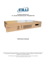
FRONT PANEL
All FMT-Series digital front panels are pretty similar; they all carry the LCD display and
function keys for operation control.
The power-on switch with internal mains signaling lamp is on the right.
www.fmuser.org

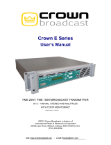
REAR PANEL CONNECTORS
RF
OUTPUT
50 OHM
EARTH
90~264V AC
50/60 Hz 80VA
FUSE 3A/250V
AUDIO INPUT
RIGHT
LEFT
EXTERNAL
AUX
10-100000 Hz
20-100 KHz
ANT.
EARTH
90~264V AC
50/60 Hz 80VA
FUSE 3A/250V
PHONE STEREO
MONITOR
20-100 KHz
MPX
LEFT
RIGHT
AUDIO OUTPUT
All STL input and out put are allocated on the rear panel. They are:
z The audio channels sockets on balanced female XLR-type connectors.
z The wide-band external processed / stereo composite signal input/output on a
grounded, unbalanced BNC connector.
z The low-frequency limited (20k~100kHz) auxiliary channel input on a
grounded, unbalanced BNC connector for transmitter.
z The RF antenna connector, N-type.
z The hot center-pin on the “EXTERNAL” BNC input in physically in parallel
with the signal + input (pin3) on the mono/right channel XLR socket. For
this reason both connectors cannot be used at the same time.
z This panle also carries the IEC-type mains socket with fuse and an earth
screw for system earthing, besides the ground ping on mains socket.
www.fmuser.org

INSTALLATION AND USE
STL TRANSMITTERS
FOREWORD TO INSTALLATION
Install the transmitter in a dry, vented, dust-free environment, with a mean
temperature of +10~+35 °C. Do not install on surfaces or racks subjected to vibrations,
external vibrations can impair S/N ratio.
Connect your audio source using suitable cables and connectors.
The STL10 Series audio circuitry is similar to hi-fi equipment and should be installed
and wired with the same attention; avoid earth loops as much as possible. When these
conditions are met, the transmitter will deliver excellent audio characteristics.
The STL10 Series are fully RF shielded and can be installed close to the production
studio, this type of installation allows constant monitoring of audio levels, deviation and
power parameters. The transmitter can also be installed in other locations away from the
studio and connected with several meters of LF co-axial cables with no adverse effect on
modulation quality. Remote installation usually requires STL (Studio to Transmission Link
equipment).
Final modulation performance is based upon the system installation, give careful
consideration to where you will locate the transmitter. Additional advices are given in
the appropriate paragraphs in this manual to assist you to achieve an optimum
environment.
www.fmuser.org

RF CONNECTION
Connect the N type output connector, marked "RF OUT" to the antenna system with
top-grade 50-ohm shielded cable.
Note: Although most 50-ohm specified cable has enough power management
capability, its power attenuation can be too high and may excessively lower the power
available to the antenna. For this reason use only low-attenuation type cable; we suggest
RG213 cable or in certain applications, where the power is over dimensioned or the cable
length is small, RG58 cable can be used. Times Microwave, Cell Flex, Andrews all
manufacture high quality low loss coax.
POWER UP
1) Connect transmitter to mains, check the ground, switch on.
Menu will display the model and firmware version. “Our ODM Series will display the
customer’s information”
If this is the first boot or you need to change the systems configuration select “No” by
pressing the ► button. If no changes are made the unit press the “set” button unit will
perform a 10 second internal self test, once complete the LCD will look like this:
www.fmuser.org

.
Initially, the PLL requires sometime to lock onto your frequency. During this phase
the LCD will display “UNLOCK” and “**INH** PLL UNLOCK” alarm.
Once locked onto your frequency the display will show “LOCKED” and “NORMAL
STATE”. At this point the transmitter will begin delivering power to your antenna.
www.fmuser.org

SETTING FREQUENCY AND TRANSMIT POWER
From the main menu, press “SET” for 3 seconds, the LCD will display the setup
mode. You should see FREQ with the [ ***.**MHz ] in blocks.
Use “▲” “▼” keys to change frequency, press and hold for fast forward, for fine
tune press and release. You can select any frequency in 10 kHz steps.
Once you have set the frequency use the “◄” “►” keys to change to the next
parameter. This will display the output power “PS” with the PS in [ 0 ] blocks use the
“▲" “▼" keys to set the power from zero to maximum. Power output is displayed
as “FWD:” reflected power is displayed as “REF”.
Correct operation will be within a range where the reflected power should be less
than 10% of the forward power. In the event your reflected power exceeds 10% you
should immediately inspect all connections, coax cable/feed line, antenna connection
or antenna match/tune.
Check the transmitter's maximum output power does not harm the downstream
amplifier stage (if any). If needed, set output power to the minimum.
Once you have finished setting the frequency and power press “SET” for 3 seconds
again; this will save your new settings to the unit’s memory. All parameters will be
saved even during a power outage or reboot.
www.fmuser.org

Use the “▲" “▼" keys to move to the next display parameter.
Next, we will repeat the setup mode in the audio display, press “SET” for 3
seconds or until you see the [ ] blocks.
The [ ] blocks will be in “MODE” area. Use the “▲" “▼" keys to change from
Stereo to Mono, when you have selected stereo/mono press the “►” key, this will
advance the selection to “PR” change the pre-emphasis by pressing either “▲"
“▼" keys, now press the “►” key the blocks will advance to “LIM” the units on-board
limiter, to make changes press the “▲" “▼" keys, press the “►” key once more
and it will highlight the L/R: Audio input level, use the “▲" “▼" keys to select the
audio level, now press the “►” key once more the blocks advance to the “A"
section, “Auxiliary Channel" again use the “▲" “▼" keys, to make your
selection. Once finished remember to press “SET" for 3 seconds for the new
parameters to be saved to the units memory. The digital menu display system is very
easy to understand and you will become familiar with its functions very quickly.
www.fmuser.org

LF CONNECTION
Pre-emphasis setting “PR:”
Low frequency and stereo channel signals have to be adequately "pre-emphasized". For
this purpose, select the setting “PR” and choose 0, 25, 50, and 75μs. Factory preset is
50μs. (Europe/Pacific/South America). USA requires 75μs. When using an external
processor that employs pre-emphasis you must set the “PR” to 0.
If you need to alter the setting, select and adjust the “PR” to the required parameter.
LF wiring and impedance selection
The STL10 Series supports
balanced/unbalanced signals with selectable
input impedance.
The audio inputs can be set to 600/10K
ohm resistive impedance; factory preset is
10k ohm. They can be connected to the
balanced output of a professional mixer or to
the unbalanced output of a low cost unit
without appreciable degradation.
Selection of the input impedance is done
by jumpers JP1 and JP2 on the input board
www.fmuser.org

shown to the right; Impedance selection is silkscreened on the component mask of the
board.
LF audio mono or stereo input employ " XLR" female connectors, use balanced coaxial
cable connected to pin 3(+) and pin 2(-). Connect the ground of the driving equipment to
pin 1.
In case of unbalanced drive, input pin 2 shall be
short-circuited with ground and shield on pin 1, while the
signal shall be available on pin 3.
High impedance selection. 5K ohm instead of 10K ohm.
With a balanced audio signal, the audio cables can be
run for 100 meters.
MPX or an externally processed signal, usually an
unbalanced signal, can be supplied to the female BNC
connector, marked "EXTERNAL", which is internally parallel
wired with the mono /right channel connector: for this reason
it is not possible to connect signals to these two connectors
at the same time. Higher impedance position is 5K ohm in
this case.
Connect this input with a 50-ohm (RG58) cable up to 3
meters’ distance; if the distance exceeds several tens of
meters, use 75-ohm (RG59) or 92-ohm (RG62) cables.
The auxiliary-channel connector, also of the BNC female type, is ground as usual. Use
50-ohm (RG58) or 75-ohm (RG59) cables to connect to the driver.
LF input level range, setting and requirements
In the following paragraph we will refer to 0 dBm as the audio signal which produce
1mW on 600 ohm, i.e. a 775mVrms / 2200 mVpp sine. Irrespective of the impedance we
will continue to assume 0dBm as a LF signal whose peak is + (or-) 1100 mV.
www.fmuser.org

In the same way, when discussing the modulation, we will assume a 0dB signal
produces 100% maximum modulation, i.e. 75 kHz deviation.
There is no absolute world-wide standard regarding LF peak level as a modulation
signal for a transmitter, nor for the mean deviation. Many Broadcasters use 0 or +6 dBm as
LF peak level for 100% modulation, USA often uses +10 dBm.
Many European countries specify +6dBm for 40 kHz deviation (which is assumed to be
a "mean" modulation). This allows for 5.5dB headroom to max 75 kHz deviation, i.e. +11.5
dBm.
Higher level audio inputs and ambient noise:
High levels will stress the input circuitry of the transmitter, reducing the dynamic
distortion-free range over the nominal level (headroom). It will also reduce the quality of
audio. For this reason we recommend, whenever possible, to adopt a +6 ~ +10 dBm as
nominal peak level for audio modulation purposes.
The STl10 Series transmitters allows an input level range on the main channel of-9 ~
+6 dBm to be set for 100% modulation, with almost no difference in modulation
performances, if a high quality signal is provided. Even at the higher level, +6 dB minimum
headroom is allowed (i.e. up to 150 kHz deviation, with no distortion). Obviously this
deviation is not currently allowed by the broadcast standards and the limiter threshold
must be set at its maximum to permit undistorted performance.
The auxiliary channel's gain lies within -6 and -24 dB, with respect to 0 dBm and 100%
modulation; this input's maximum applicable level is 0 dBm (775 mV rms).
Typical input levels for an SCA-type signal (10% max. admissible deviation) may lie in
the --9 to 0 dBm range (245 - 775 mV rms / 696~2200 mV pp), when the gain is set
between -9 dB. Typical-input levels for an RDS-type signal (max. admissible peak deviation
2 kHz) may lie in the -21.5 to -11.5 dBm (185 ~ 585 mV pp) ranges, when the gain is set
between -9 dB as above.
The nominal input level to 0 dB modulation may be set with good precision on audio /
stereo composite channels, by change the gain to reach the wanted level.
www.fmuser.org

- 15 -
The auxiliary channel level is much more difficult to be precisely set, due to the wider
range of the continuously variable control, 18 dB vs. 4 dB. Nevertheless dB control is easy
to be set when applying the nominal signal from an external generator, whose level is
known, and regulating it to display the wanted modulation on the modulation meter.
The transmitter’s internal limiter is of the peak-clipping type; this means that as soon
at it cuts in, modulation distortion increases sharply. For this reason, the modulation signal
should be kept under control to prevent intervention of the limiter.
The cut-in limiter threshold is factory preset to +2.5 dB (100 kHz peak value). It may
be set from 0 dB (75 kHz) and more than +6 dB (150 kHz). This threshold value is mostly
specified in the various national standards, and tolerance to short over-modulating peaks
varies from country to country.
In any case, the modulation peak value that is internationally admitted for FM is 75
kHz for peaks that are not extremely short. For this reason, the limiter's cut-in threshold
should never be too high. It is highly recommended to use an external multi-band limiter to
optimize modulation, with higher tolerance for any audio-signal peaks. Such devices
momentarily reduce the amplifier circuits' gain if the threshold is exceeded and prevent
severe, significant distortion.
Any external compressor, limiter or audio meter must be frequency compensated with
the same time constant of the pre-emphasis to modulate or monitor deviation properly.
Therefore, the audio level shall be constantly and correctly monitored and adjusted, to
prevent as much as possible, the internal limiter from cutting in. On the other hand, the
audio level should be as high as possible, to achieve the best on-air sound.
www.fmuser.org

The tendency to over process the audio signal is common with local broadcasting
stations: some sort of processing is advisable and we recommend using a top grade
multiband compressor but not as to compress the signal to a point that impairs the original
dynamics.
The audio response of the STL10 Series is very flat, without perceivable loss on low
and high audio frequency: for these reasons large frequency alterations of the audio
signal supplied by using a so-called "frequency equalizer," are not advisable. An
increase of the low and high frequency contents of the audio signal by more than a
few dB can cause general degradation of modulation dynamics and improper
functioning of the limiter.
www.fmuser.org

OPERATION
Stereo Broadcasting with 2 Input Audio Channels:
1) Wire the XLR-type modulation input connectors, marked "Left" (channel) and "Right"
(channel), to the output of the two channels
from the mixer or stereo source.
2) Change "MODE" to "Stereo".
Mono Broadcasting, from a monophonic audio
source:
1) Wire the "right" (or mono) input connector to the corresponding audio source as above.
Please note that in this case too, the signal runs through the channel(s) processors and is
15-kHz filtered and pre-emphasized.
The FMT-Series with internal stereo-encoder is usually factory preset to process the right
channel input signal in the mono mode: it is however possible to use the left channel signal
in a similar way by moving jumper "BD1" on
the stereo encoder board from position "R" to
"L". It is also possible to mix automatically the
left and right channels for mono by inserting 2
jumpers in "L" and "R" on the encoder: the
transmitter is thereby already preset for stereo
operation if needed.
2) Move "MODE:" to "Mono" and set "L/R: " to "0dB".
www.fmuser.org

Mono or Stereo Broadcasting from Radio-Link Receiver or an External Encoder:
1) In this case, the signal is already
multiplexed and pre-emphasized. Use the
"External" or "Stereo" audio input.
The signal skips the coding and filtering
stage and therefore is not pre-emphasized.
2) Move "MODE" switch to "External".
Operation with a RDS or SCA Encoder
1) Wire the BNC-type "Aux" connector to the output of the RDS or SCA Encoder,
momentarily disconnecting any other signal, if present. Wire the pilot-tone synchronization
output to the corresponding input of RDS encoder, if present.
2) Momentarily move "MODE:" switch to "Mono".
3) Adjust RDS or SCA encoder output level and /or transmitter aux level front trimmer,
marked "aux gain", to achieve the right modulation level.
Modulation Adjustment with broadcast signal:
Check the modulation level for adequacy, as follow:
1) Send a sufficiently constant musical signal to modulator input, check that the meter
needle hovers around 0 dBm and moves into the red range during signal peak only and by
no more than 1 or2dB. For any other reading, adjust the mixer's "MASTER" volume until the
above conditions are obtained.
The "Limiter" alarm should never or very rarely shows up as this would indicate distortion.
If the limiter is set just above 75 kHz, the ”LIM” will shows up above 0dB and the
www.fmuser.org

meter will never show a much greater value. Factory preset is 100kHz (+2.5dB).
"MODE" Switch on "Mono " and “0dB”
In this position, the audio circuit gain of the transmitter is slightly below unity (90%)
and corresponds to the sensitivity obtainable in the stereo position, with pilot tone which
allows for the remaining 10%.
Use this setting exclusively to test briefly stereo-mono switch, when no volume
variation is desired in the modulation. In this case, for two-channel mono operation, it is
preferable to place two jumpers in "L" and "R" at the BDI position on the stereo encoder
board, to use both channel mixed in transmission.
For protracted mono broadcasting, use the position "Mono” “0dB", which permits
correct 100% modulation with 0dB level, as indicated by the internal meter.
Low power level transmission
The FMT-Series transmitters are not specified at power level less than 2 Watt, as with
some power and frequency combinations (usually at less than 0.5 Watt, some
sub-harmonic and/or spurious signals may be generated.
Were low power level transmission was imperative, verify with a spectrum analyzer
that the transmitter is correctly functioning at and just below the operation power: lowering
the exciter to final amplifier power, via the exciter board power regulator, may help and
even completely fix the problem.
The installation of the transmitters is thereby completed. D&M wishes you success in
your work and remind you that they are always available for further information or to tackle
any specific problem.
www.fmuser.org

STL RECIEVER
FOREWORD TO INSTALLATION
Install the RECIEVER in a dry, vented, dust-free environment, with a mean temperature
of +10~+35 °C. Do not install on surfaces or racks subjected to vibrations, external
vibrations can impair S/N ratio.
Connect your audio source using suitable cables and connectors.
The STL10 Series audio circuitry is similar to hi-fi equipment and should be installed
and wired with the same attention; avoid earth loops as much as possible. When these
conditions are met, the transmitter will deliver excellent audio characteristics.
The STL10 Series are fully RF shielded and can be installed close to the production
studio, this type of installation allows constant monitoring of audio levels, deviation and
power parameters. The transmitter can also be installed in other locations away from the
studio and connected with several meters of LF co-axial cables with no adverse effect on
modulation quality. Remote installation usually requires STL (Studio to Transmission Link
equipment).
Final modulation performance is based upon the system installation, give careful
consideration to where you will locate the transmitter. Additional advices are given in
the appropriate paragraphs in this manual to assist you to achieve an optimum
environment.
www.fmuser.org
/