Page is loading ...

R5976426
user’s manual

R5976426
Title: CYCLOPS User’s Manual
ID-no.:
R5976426
Date: 2001-12
main issue update
chapter 1 new
chapter 2 new
chapter 3 new
chapter 4 new
chapter 5 new
chapter 6 new
chapter 7 new
chapter 8 new
chapter 9 new
chapter 10 new
chapter 11 new
chapter 12 new
chapter 13 new
chapter 14 new
chapter 15 new
new: The corresponding chapters are new or completely revised.
corr.: Passages of the corresponding chapter were corrected; see modification bars.
add.: Passages of the corresponding chapter were added; see modification bars.
Document History
Modifications which result in a new version are indicated by a vertical bar.
Keep this sheet!

Trademarks
Brand and product names mentioned in this manual may be trademarks, registered trademarks or
copyrights of their respective holders. All brand and product names mentioned in this manual
serve as comments or examples and are not to be understood as advertising for the products or
their manufacturers.
Copyright © 2001 by Barco Control Rooms GmbH
Die Weitergabe sowie die Vervielfältigung aller Unterlagen, die von uns überlassen werden, deren
Verwertung und Mitteilung ihres Inhaltes an Dritte ist nicht gestattet, soweit dies nicht ausdrück-
lich zugestanden ist. Urheberrechte, insbesondere auch solche an Software, werden nur insoweit
übertragen, als es für die Erreichung des speziellen Vertragszwecks erforderlich ist. Zuwider-
handlungen können zu Schadensersatz verpflichten. Alle Rechte aus der Erteilung eines Patents
oder der Eintragung eines Gebrauchsmusters verbleiben bei uns.
Copyright © 2001 by Barco Control Rooms GmbH
All rights reserved. No part of this document may be copied, reproduced or translated. It shall not
otherwise be recorded, transmitted or stored in a retrieval system without the prior written consent
of Barco Control Rooms GmbH.
Guarantee and Compensation
Barco Control Rooms GmbH provides a guarantee relating to perfect manufacturing as part of the
legally stipulated terms of guarantee. On receipt, the purchaser must immediately inspect all deliv-
ered goods for damage incurred during transport, as well as for material and manufacturing faults.
Barco Control Rooms GmbH must be informed immediately in writing of any complaints.
The period of guarantee begins on the date of transfer of risks, in the case of special systems and
software on the date of commissioning, at the latest 30 days after the transfer of risks. In the event
of justified notice of complaint, Barco Control Rooms GmbH can repair the fault or provide a re-
placement at its own discretion within an appropriate period. If this measure proves to be impossi-
ble or unsuccessful, the purchaser can demand a reduction in the purchase price or cancellation of
the contract. All other claims, in particular those relating to compensation for direct or indirect
damage, and also damage attributed to the operation of software as well as to other services pro-
vided by Barco Control Rooms GmbH, being a component of the system or independent services,
will be deemed invalid provided the damage is not proven to be attributed to the absence of prop-
erties guaranteed in writing or due to the intent or gross negligence on the part of Barco Control
Rooms GmbH
If the purchaser or a third party carries out modifications or repairs on good delivered by Barco
Control Rooms GmbH, or if the goods are handled incorrectly, in particular if the systems are
commissioned or operated incorrectly or if, after the transfer of risks, the goods are subject to in-
fluences not agreed upon in the contract, all guarantee claims of the purchaser will be rendered in-
valid. Not included in the guarantee coverage are system failures which are attributed to programs
or special electronic circuitry provided by the purchaser, e. g. interfaces. Normal wear as well as
normal maintenance are not subject to the guarantee provided by Barco Control Rooms GmbH ei-
ther.
The environmental conditions as well as the servicing and maintenance regulations specified in
this manual must be complied with by the customer.

Revision sheet
To:
Barco Control Rooms GmbH
An der Rossweid 5 • D-76229 Karlsruhe • Germany
Phone (49) (721) 6201-0 • Fax (49) (721) 6201-298
E-mail
docu.de.bcd@barco.com, Web www.barcocontrolrooms.de
BARCO N.V. Projection Systems
Noordlaan 5 • B-8520 Kuurne • Belgium
Phone (32) (56) 36-8211 • Fax (32) (56) 36-8251
E-mail
sales.bcd@barco.com• Web www.barcocontrolrooms.com
From:
Date:
Please correct the following points in this documentation (R5976426)
page wrong correct

Contents
1 Introduction.................................................................................................................................. 1-1
1.1 How This Manual Is Organized .......................................................................................... 1-2
1.2 Styles And Symbols ............................................................................................................ 1-3
1.3 Safety Information............................................................................................................... 1-4
1.3.1 Precautions.................................................................................................................. 1-6
1.3.2 Unpacking of Devices ................................................................................................1-6
1.3.3 Modification of Devices ............................................................................................. 1-6
2 Abbreviated Summary ................................................................................................................. 2-1
2.1 Design.................................................................................................................................. 2-2
2.2 Properties of C
YCLOPS ........................................................................................................ 2-2
3 Design and Function .................................................................................................................... 3-1
3.1 Components of Cyclops ...................................................................................................... 3-2
3.1.1 Structure...................................................................................................................... 3-2
3.1.2 Deflection Mirror........................................................................................................ 3-2
3.1.3 Projection System .......................................................................................................3-2
3.1.4 Screen Module............................................................................................................ 3-3
4 Location and Functions of Control .............................................................................................. 4-1
4.1 Access.................................................................................................................................. 4-2
4.2 Control Unit......................................................................................................................... 4-2
4.2.1 Power, source and communication connections [1]................................................... 4-2
4.3 Control Panel Terminology................................................................................................. 4-3
4.3.1 Local keypad............................................................................................................... 4-3
4.3.2 Remote control ........................................................................................................... 4-4
4.3.3 Terminology of keypad and RCU controls ................................................................4-5
5 Connections.................................................................................................................................. 5-1
5.1 Power connection ................................................................................................................5-2
5.1.1 AC Power (mains) cord connection ........................................................................... 5-2
5.1.2 Fuses ........................................................................................................................... 5-2
5.1.3 Switching on ...............................................................................................................5-2
5.1.4 Image projection .........................................................................................................5-2
5.1.5 Lamp Run Time..........................................................................................................5-2
5.1.6 Switching to Stand-by ................................................................................................5-3
5.1.7 Switching Off.............................................................................................................. 5-3
5.1.8 Input Connections....................................................................................................... 5-3
5.1.9 Set up of the input selection: ...................................................................................... 5-4
5.1.10 5-cable Input Slot (slot 1) ......................................................................................... 5-4
5.1.11 Computer input/Monitor output ............................................................................... 5-6
5.1.12 Video Input ............................................................................................................... 5-6
5.1.13 S-Video Input ........................................................................................................... 5-7
5.1.14 Serial Digital Input / Serial Digital Output............................................................... 5-7
5.1.15 IEEE 1394 Input ....................................................................................................... 5-7
5.1.16 Communication Connections ................................................................................... 5-8

5.1.17 RS232 in / RS232 out ............................................................................................... 5-8
5.1.18 Communication port for communication with peripherals ......................................5-8
5.1.19 TRIG Output............................................................................................................. 5-9
5.1.20 MOUSE ....................................................................................................................5-9
5.1.21 Audio Connections ................................................................................................... 5-9
6 Controlling ................................................................................................................................. 6-10
6.1 RCU used in a hardwired configuration............................................................................ 6-11
6.2 How to use the RCU?........................................................................................................ 6-11
6.3 Projector address ............................................................................................................... 6-11
6.3.1 Using the RCU.......................................................................................................... 6-11
6.3.2 Displaying a Projector Address ................................................................................ 6-11
6.3.3 How to Program an Address into the RCU? ............................................................6-11
6.3.4 Picture Controls with Direct Access......................................................................... 6-12
6.3.5 Sound controls with direct access............................................................................. 6-13
7 Start Up of the Adjustment Mode................................................................................................ 7-1
7.1 Adjustment mode ................................................................................................................7-2
7.1.1 Password ..................................................................................................................... 7-2
8 Random Access Adjustment Mode.............................................................................................. 8-1
8.1 File Service.......................................................................................................................... 8-2
8.1.1 Load File..................................................................................................................... 8-3
8.1.2 Edit File ......................................................................................................................8-4
8.1.3 Rename ....................................................................................................................... 8-6
8.1.4 Copy............................................................................................................................ 8-7
8.1.5 Delete.......................................................................................................................... 8-7
8.1.6 File Options ................................................................................................................8-8
8.2 Picture Tuning ..................................................................................................................... 8-8
8.2.1 Color Temperature...................................................................................................... 8-9
8.2.2 Gamma........................................................................................................................ 8-9
8.2.3 Color Depth .............................................................................................................. 8-10
8.2.4 Black Color...............................................................................................................8-10
8.2.5 Audio Tuning............................................................................................................ 8-10
8.2.6 Volume, Balance, Bass and Treble........................................................................... 8-10
8.2.7 Mute.......................................................................................................................... 8-11
8.2.8 Fade........................................................................................................................... 8-11
8.2.9 Mode [stereo]/[mono]............................................................................................... 8-11
8.2.10 Video - Audio lock ................................................................................................. 8-11
8.3 Geometry ...........................................................................................................................8-12
8.3.1 Shift........................................................................................................................... 8-12
8.3.2 Size ........................................................................................................................... 8-13
8.3.3 Side Keystone ........................................................................................................... 8-13
8.3.4 Blanking.................................................................................................................... 8-13
8.3.5 Aspect Ratio [5:4]/[4:3]/[16:9]................................................................................. 8-13
8.3.6 Options...................................................................................................................... 8-14

9 Installation Mode ......................................................................................................................... 9-1
9.1 Input Slots............................................................................................................................ 9-2
9.2 800 Peripheral...................................................................................................................... 9-3
9.3 Configuration....................................................................................................................... 9-3
9.4 OSD color (On-Screen Display) .........................................................................................9-3
9.5 Internal Patterns................................................................................................................... 9-4
9.6 Lens Adjustments................................................................................................................ 9-5
9.7 Quick Access Keys.............................................................................................................. 9-5
9.8 Internal Patterns................................................................................................................... 9-6
10 Service Mode ........................................................................................................................... 10-1
10.1 Identification ...................................................................................................................10-2
10.2 Change Password ............................................................................................................ 10-2
10.3 Change Language ............................................................................................................ 10-3
10.4 Change Projector Address............................................................................................... 10-3
10.5 Change Baudrate PC ....................................................................................................... 10-4
10.6 Reset Lamp Runtime....................................................................................................... 10-4
10.7 Lamp Runtime History.................................................................................................... 10-4
10.8 BARCO logo ................................................................................................................... 10-5
10.9 Panel Adjustment ............................................................................................................ 10-5
10.10 Uniformity ..................................................................................................................... 10-6
10.11 Preset Input Balance...................................................................................................... 10-6
10.12 I2C Diagnosis. ............................................................................................................... 10-6
11 Maintenance and Servicing...................................................................................................... 11-1
11.1 General ............................................................................................................................ 11-2
11.2 Cleaning........................................................................................................................... 11-2
11.2.1 Cleaning the Screen ................................................................................................ 11-2
11.2.2 Lens Cleaning Procedure........................................................................................11-2
12 Technical Data ......................................................................................................................... 12-1
12.1 General Data.................................................................................................................... 12-2
12.2 Technical Data of Optical System................................................................................... 12-2
12.3 Technical Data Of Electrical System .............................................................................. 12-3
12.3.1 Slot 1: 5 cable input, 5×BNC ................................................................................. 12-3
12.3.2 Slot 2: Computer input/Monitor output.................................................................. 12-3
12.3.3 Slot 3: Video Input .................................................................................................12-4
12.3.4 Slot 4: S-Video Input.............................................................................................. 12-4
12.3.5 Slot 5: Serial digital Input / Serial digital Output................................................... 12-4
12.4 Parts List.......................................................................................................................... 12-5

12.4.1 Scope of Delivery of R9831150 ............................................................................. 12-5
12.4.2 Optional Parts ......................................................................................................... 12-5
12.4.3 User’s Manuals ....................................................................................................... 12-5
12.5 Addresses......................................................................................................................... 12-5
13 Troubleshooting ....................................................................................................................... 13-1
13.1 Faults ............................................................................................................................... 13-2
13.2 Contact............................................................................................................................. 13-3
13.2.1 Hot Line .................................................................................................................. 13-3
14 Appendix A: Standard Source Set Up Files............................................................................. 14-1
15 Appendix B: Source Numbers 81 - 86 And 91 - 96................................................................. 15-4
15.1 Projector without any 800 peripheral connected............................................................. 15-4
15.2 Projector with a 800 peripheral connected...................................................................... 15-4
15.2.1 Source numbers 91 - 99. ......................................................................................... 15-4
15.2.2 Source numbers 81 - 86 .......................................................................................... 15-5

1 Intro duction
This manual describes design, function, operation and maintenance of the modular rear projection
system C
YCLOPS of BARCO.
C
YCLOPS is a modular structure to house a 3-panel Poly-Silicon LCD projector. Cyclops 100S has
a screen diagonal of approx. 100" (98"), up to 2 units can be piled up. In horizontal direction the
number of units to be aligned depends on the operating conditions (temperature, relative humid-
ity).
The projector of C
YCLOPS has native SXGA resolution (5:4 aspect ratio) and allows you to display
a wide variety of common video and RGB sources. The display can be controlled via an IR remote
control or via an integrated keypad.

CYCLOPS (2001-12) R5976426 1-2
1.1 How Th is Manual Is Organized
This manual is divided into fifteen chapters:
Preliminary Remarks
explains the structure of the manual itself and the used typographic styles and symbols. Safety
information is provided concerning the operation of systems from BARCO.
Summary
provides a summary of the system components and characteristics.
Design and Functions
provides a technical description of the equipment listing the fundamental characteristics and
functional principles. Knowledge of this section is not absolutely essential for operation.
Location and Functions of Control
describes the functions and explains the control panel terminology
Connections
describes the interfaces of CYCLOPS
Controlling
explains how CYCLOPS is operated via the Remote Control Unit and the local keypad
Start Up of the Adjustment Mode
explains how to use the menu controlled software of CYCLOPS
Random Access Adjustment Mode
provides an overview of the commands of CYCLOPS
Installation Mode
describes the possible configurations of CYCLOPS
Service Mode
explains the commands which are available in Service Mode
Maintenance and Servicing
explains how the equipment can be serviced
Technical Data
provides tabular overviews about the technical details of CYCLOPS.
Troubleshooting
lists possible errors together with steps to eliminate the respective fault.
Appendix A: Standard Source Set Up Files
lists all the available set up files for the various timings
Appendix B: Source Numbers 81-85 AND 91-96
explains the relationship between source input, source number and set up file
Chapters, pages, figures and tables are numbered separately. Chapters are indicated by a »point
syntax«, e. g.
4.2.3, pages by a »dash syntax«, e. g. 2-1, as figures and tables are, e. g. Figure 5-4.

CYCLOPS (2001-12) R5976426 1-3
1.2 Styles And Symbols
The typographic styles and the symbols used in this document have the following meaning:
Arial bold
Labels, menus and buttons are printed in the Arial bold font.
Condensed
Links to both other chapters of this manual and to sites in the Internet are printed condensed. In the
on-line version of this manual all hyperlinks appear
teal.
Courier
Names of files and parts from programs are printed in the Courier font.
Courier bold
Inputs you are supposed to do from the keyboard are printed in Courier bold font.
Within a piece of programming code this arrow marks a line, that must be made up
in two lines, though meant to be one line.
This arrow marks tips and notes.
If you do not heed instructions indicated by this symbol there is a risk of damage to
the equipment!
If you do not heed instructions indicated by this symbol there is a risk of electrical
shock and danger to personal health!

CYCLOPS (2001-12) R5976426 1-4
1.3 Safety Information
This section describes safety precautions which must be observed when installing a product from
BARCO.
Safetey
CYCLOPS is built in accordance with the requirements of the international safety standard IEC950,
UL1950 and CSA C22.2 No. 950, which are the safety standards of information technology
equipment including electrical business equipment.
The safety standards of information technology equipment impose important requirements on the
use of safety critical components, materials and isolation, in order to protect the user or operator
against the risk of electric shock and energy hazard, and having access to live parts.
Safety standards also impose limits to the internal and external temperature rises, radiation levels,
mechanical stability and strength, enclosure construction and protection against risk of fire.
Simulated single fault condition testing ensures the safety of the equipment to the use even when
the equipment’s normal operation fails.
General safety instructions
All the safety and operating instructions should be read before using this unit.
The operating instructions manual should be retained for future reference.
All warnings on the device and in the documentation manuals should be adhered to.
All instructions for operating and use of this equipment must be followed precisely.
Installation and Service
Installation and preliminary adjustments should be performed by qualified BARCO personnel or
authorized BARCO service dealers.
On Safety
Check the power rating on your outlet before connecting the devices to the wall
outlet or to a power strip. Contact your facilities manager or a qualified electrician if
you are not sure what type of power is supplied to your building.
The devices are designed to operate with single-phase power systems having a
grounded neutral conductor. To reduce the risk of electrical shock, do not plug into
any other type of power system.
A. Mains lead (AC Power cord) with CEE 7 plug:
The colors of the mains lead are colored in accordance with the following code:
Green-and-yellow: Earth (safety earth)
Blue: Neutral
Brown: Line (live)

CYCLOPS (2001-12) R5976426 1-5
B. Power cord with ANSI 73.11 plug:
The wires of the power cord are colored in accordance with the following code:
Green/yellow: Ground
White: Neutral
Black: Line (live)
Do not allow anything to rest on the power cord. Do not locate this product where persons will
walk on the cord.
To disconnect the cord, pull it out by the plug. Never pull the cord itself.
If an extension cord is used with this product, make sure that the total of the ampere ratings on
the products plugged into the extension cord does not exceed the extension cord ampere rating.
Also make sure that the total of all products plugged into the wall outlet does not exceed 15
amperes.
Never push objects of any kind into this product through cabinet slots as they may touch dan-
gerous voltage points or short out parts that could result in a risk of fire or electrical shock.
Never spill liquid of any kind on the product. Should any liquid or solid object fall into the
cabinet, unplug the set and have it checked by qualified service personnel before resuming op-
erations.
Warning: Do Not Place Flammable or Combustible Materials Near Projector!
BARCO products are designed and manufactured to meet the most stringent safety regulations.
Exposing flammable or combustible materials into close proximity of this device could result in
the spontaneous ignition of that material, resulting in a fire. For this reason, it is absolutely neces-
sary to leave an "exclusion zone" around all external surfaces of the projector whereby no flam-
mable or combustible materials are present. The exclusion zone must be not less than 10 cm (4").
Do not cover the projector with any material while the projector is in operation.
Keep flammable and combustible materials away from the projector at all times. Mount the pro-
jector in a well ventilated area away from sources of ignition and out of direct sun light. Never ex-
pose this product to rain or excessive moisture. In the event of fire, use sand, CO
2
, or dry powder
fire extinguishers; never use water on an electrical fire.
Always have service performed on this product by authorized BARCO service personnel. Always
insist on genuine BARCO replacement parts. Never use non-BARCO replacement parts as they
may degrade the safety of this device.
Use only the power cord supplied with your device. While appearing to be similar, other power
cords have not been safety tested at the factory and may not be used to power the projector. For a
replacement power cord, contact your dealer.
Slots and openings in the cabinet and the sides are provided for ventilation; to ensure reliable op-
eration of the device and to protect it from overheating, these openings must not be blocked or
covered. This product should never be placed near or over a radiator or heat register. This product
should not be placed in a built-in installation or enclosure unless proper ventilation is provided.

CYCLOPS (2001-12) R5976426 1-6
On Servicing
Do not attempt to service this device yourself, as opening or removing covers may expose you to
dangerous voltage potential and risk of electric shock! Refer all projector service to a qualified
BARCO service center.
Adjust only those controls that are covered by the operating instructions since improper adjust-
ment of the other controls may result in damage and will often require extensive work by a quali-
fied technician to restore the product to normal operation.
Call for service in the following conditions :
When the power cord or plug is damaged or frayed.
If liquid has been spilled into the device.
If the product has been exposed to rain or water.
If the product does not operate normally when the operating instructions are followed.
If the product has been dropped or the cabinet has been damaged;
If the product exhibits a distinct change in performance, indicating a need for service.
When replacement parts are required, be sure the service technician has used original BARCO re-
placement parts or authorized replacement parts which have the same characteristics as the
BARCO original part. Unauthorized substitutions may result in degraded performance and reli-
ability, fire, electric shock or other hazards. Unauthorized substitutions may void warranty.
Upon completion of any service or repairs to this unit, ask the service technician to perform safety
checks to determine that the unit is in proper operating condition.
1.3.1 Precaut ions
For your own protection, observe the following safety precautions when installing your device!
Observe all warnings and instructions printed on the devices!
Check that the voltage and frequency of your power supply match those printed on the device
label with the rated electrical values!
Servicing not explicitly mentioned in this manual should never be carried out by unauthorized
personnel!
1.3.2 Unpack ing of Devices
Note advises on the packaging for unpacking!
1.3.3 Modific ation of Devices
Mechanical or electrical modifications others than described in this manual must not be made to
the devices. BARCO is not liable for damages resulting from modified devices.
Only authorized personnel should carry out other maintenance work not explicitly
mentioned in this user's manual!
Never open the case of the power supply or of the projection unit without first dis-
connecting the power supply cord! Measurements and tests with an opened device
may be carried out only in the factory or by specially trained personnel, due to the
dangers of electrical shock.

2 Abbr eviated Summary
This chapter provides a summary of the system components and characteristics.

CYCLOPS (2001-12) R5976426 2-2
2.1 Design
High-quality and large-area displaying of monitor contents is becoming increasingly important in
conference and presentation theaters, at exhibitions, in public areas of insurance companies, banks,
hotels or transport services. Personal computers are primarily used in this context, but also UNIX
workstations. Simple data presentations are being increasingly supplemented by multimedia appli-
cations with video displays. C
YCLOPS provides optimum solutions which also satisfy the highest
demands. C
YCLOPS is multimedia-compatible since it can be connected to any current source
(digital and analog camcorder sources, analog video tape sources, DVD, Laserdisc, digital video
tape sources, computer data sources). Audio reproduction is possible by connecting amplifiers or
active boxes to the audio socket. Personal computers with the following graphics adapters can be
connected as the data sources: SXGA, XGA, SVGA, VGA. Workstations, Apple Macintosh and
Power Macintosh are also supported. Remote real-time switching is possible between all sources.
C
YCLOPS can be used as one large monitor with a screen diagonal of 100 inches – or multiple units
can be combined to achieve an impressive Display Wall. C
YCLOPS is designed for long term op-
eration in control rooms and each application can benefit from the high reliability and ease of use.
2.2 Proper ties of C
YCLOPS
CYCLOPS can be used as one large monitor with a screen diagonal of 100 inches. The technologies
used guarantee the best optical properties for high-quality presentation of both computer data and
video displays:
High, Constant Reading Accuracy Over the Complete Display Panel
Optimally adjusted high-performance lens systems guarantee a distortion-free and sharp image.
Bright Displays
A 120 W UHP lamp provides a high luminous flux which is passed on at great efficiency by
the illumination system.
High Contrast
The screen has a surface which absorbs ambient light falling on it and increases the contrast.
Easy Adjustment and Low-maintenance
Readjustment of the components is not required. The operation time of the lamps is about 6000
hours.
Ready for any application
The source is automatically recognized. The projector has intelligent and user-adjustable prior-
ity switching.

3 Desig n and Function
This chapter provides a technical description of the equipment listing the fundamental characteris-
tics and functional principles. Knowledge of this section is not absolutely essential for operation.

CYCLOPS (2001-12) R5976426 3-2
3.1 Compo nents of Cyclops
C
YCLOPS consists of the following components:
Mechanical structure: the metal housing incorporates the projector, mirror and screen.
Projector: The projector employed in C
YCLOPS is based on most modern 3-panel poly-Silicon
LCD technology. It is an independent device, including lamp, control unit, interfaces. The
projector is mounted on a support; once adjusted, the position is locked, and no re-adjustment
is needed.
Deflection mirror: a mirror in the top part of the housing deflects the light onto the rear of the
projection screen.
For Cyclops 100S, two kinds of screen are available, a double element Fresnel-Lenticular
screen with high gain and a single element diffusion screen with high vertical and horizontal
viewing angles (important when sitting close to the wall)
3.1.1 Structu re
The structure incorporates the projector, the mirror, and the screen. All elements are optically ad-
justed to provide an optimized image. Due to the principle of rear projection, high contrast ratio is
provided even at daylight.
If required, Cylops can be outfit with an architectural trim around the screen and/or a cladding.
3.1.2 Deflecti on Mirror
Due to folding up the optical path by a mirror the entire depth of CYCLOPS is only
1487 millimeters.
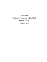
3.1.3 Projecti on System
The projector is mounted via a support. The light path is folded up by a mirror to shorten the in-
stallation depth. The image is projected onto the rear of the screen.
1
2
3
1 Projector
2 Mirror
3 Screen

CYCLOPS (2001-12) R5976426 3-3
Figure 3-1
Poly-Silicon TFT-LCD
The LCD panels are based on Poly-Silicon technology. Poly-Silicon material consists of nu-
merous small crystals leading to small circuitry. The results are a big aperture (ratio of a pixel’s
shutter area to it’s total area), high speed and reliability. The panels have 1,310,720 (SXGA
1280×1024) pixels.
3.1.4 Screen Module
The image is generated in the screen module.
Two kinds of screens are available, a double element Fresnel-Lenticular screen with a high gain
and a single element diffusion screen, which, due to its excellent white field uniformity, is recom-
mended when sitting close to the wall.
Fresnel-Lenticular Screen
The screen is a double element system with 4 active lens surfaces for optimum light control. It
combines high brightness uniformity with a fine pitch and wide viewing angles. The rear element
consists of a Fresnel lens which directs all projected light forwards at a right-angle. The first len-
ticular lens on the front element of the screen controls vertical viewing angles. The unique profile
of the wide angle lenticular lens distributes the light horizontally.
Fresnel Lens
The Fresnel lens deflects the light coming from the projection lens system such that it falls
perpendicularly onto the lenticular screen.
Lenticular Lens
The lenticular lens guarantees that the light is distributed horizontally.

CYCLOPS (2001-12) R5976426 3-4
Diffusion Screen
Diffusion screens distribute the projected light evenly over a wide horizontal and vertical viewing
area. The reflection value (gain) is 1.They are appreciated for their versatility. It is a perfect choice
for any application which requires a wide viewing angle or where ambient light conditions are
controllable.
1/81