
TeleWell TW-EA400
User’s Manual
Ver. 1.0
Version 2

2
Table of Contents
1. Introduction................................................................................................4
1.1 ROUTER DESCRIPTION AND OPERATION.............................................................4
1.2 ADSL TECHNOLOGY ...........................................................................................4
1.3 PRODUCT FEATURES ...........................................................................................5
1.4 STANDARDS COMPATIBILITY AND COMPLIANCE ..................................................7
1.5 FRONT PANEL ......................................................................................................8
1.6 REAR PANEL ........................................................................................................8
1.7 LED INDICATORS .................................................................................................8
1.8 PACKAGE CONTENTS...........................................................................................8
2 Hardware Installation..................................................................................9
2.1 CONNECT THE POWER ........................................................................................9
2.2 CONNECT ADSL LINE .........................................................................................9
2.3 CONNECT ETHERNET LAN TO ROUTER..............................................................9
2.4 RESET ..................................................................................................................9
3. System Requirements .............................................................................10
4. Software Installation ................................................................................11
4.1 PC TCP/IP SETTINGS.......................................................................................11
4.2 ADSL ROUTER SETTINGS.................................................................................14
5. Status ........................................................................................................15
5.1 HOME PAGE .......................................................................................................15
5.2 ADSL STATUS PAGE..........................................................................................16
5.3 LAN PAGE .........................................................................................................17
5.4
PPP PAGE .........................................................................................................18
6. Configuration ...........................................................................................19
6.1
WAN CONFIGURATION ......................................................................................19
MAC Spoofing.................................................................................................20
ATM .................................................................................................................20
Encapsulation/Bridge.......................................................................................21
IGMP................................................................................................................22
PPP/DHCP .......................................................................................................23
6.2 LAN CONFIGURATION .......................................................................................24
DHCP Server....................................................................................................24
Ethernet Mode Setting .....................................................................................26
6.3 PPP CONFIGURATION .......................................................................................26
6.4 NAT CONFIGURATION........................................................................................28
6.5 VIRTUAL SERVER CONFIGURATION ...................................................................30
6.6 DNS CONFIGURATION.......................................................................................31
6.7 BRIDGE FILTERING.............................................................................................32

3
6.8 SAVE SETTINGS .................................................................................................33
6.9 REBOOT WITHOUT SAVING .................................................................................33
7. Admin Privilege........................................................................................34
7.1 WAN STATUS ....................................................................................................34
7.2 ATM STATUS ......................................................................................................34
7.3 TCP STATUS ......................................................................................................35
7.4 ROUTE TABLE ....................................................................................................35
7.5 LEARNED MAC TABLE.......................................................................................36
7.6 ADSL CONFIGURATION .....................................................................................37
7.7 RIP CONFIGURATION.........................................................................................38
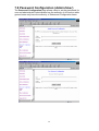
7.8 PASSWORD CONFIGURATION (ADMIN/USER)....................................................40
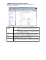
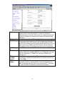
7.9 MISCELLANEOUS CONFIGURATION....................................................................41
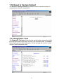
7.10 RESET TO FACTORY DEFAULT .........................................................................43
7.11 DIAGNOSTIC TEST ...........................................................................................43
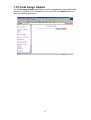
7.12 CODE IMAGE UPDATE......................................................................................44
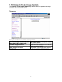
7.13 NETWORK CODE IMAGE UPDATE ....................................................................45
Firmware..........................................................................................................45
Boot Code ........................................................................................................46
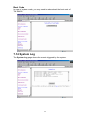
7.14 SYSTEM LOG ...................................................................................................46
8. Technical Specifications .........................................................................47
Appendix A. ..................................................................................................48
Appendix B...................................................................................................49

4
1. Introduction
This chapter describes the TW-EA400 ADSL Router and its features and gives
a brief introduction to ADSL technology.
1.1 Router Description and Operation
TW-EA400 ADSL Router combines an “always-on” high speed Asymmetric
Digital Subscriber Line (ADSL) connection to the telephone line into a single
cost-effective solution.
TW-EA400 ADSL Router is compliant with the full-rate ANSI T1.413 Issue 2
and ITU G.dmt (G.992.1) ADSL standards, and with the splitterless ITU G.lite
(G.992.2) specification. Both Annex A (ADSL over POTS) and Annex B (ADSL
over ISDN) of G.992.1 and G.992.2 are supported. This rate-adaptive solution
is designed for Customer Premise Equipment and supports downstream data
rates of up to 8 Mbps and upstream data rates of up to 1 Mbps.
TW-EA400 ADSL Router simultaneously supports Ethernet to enable the
widest array of host connectivity. The Router performs ATM Segmentation and
Reassembly (SAR), industry standards for PPP over ATM (RFC 2364),
bridged/routed Ethernet over ATM (RFC 1483), Classical IP over ATM (RFC
1577), and PPP over Ethernet (RFC 2516), resulting in a cost-effective
solution suitable for both full rate and G.lite applications. The non-reliance on
host PC software drivers make the TW-EA400 ADSL Router ideal for
ubiquitous broadband connectivity that is not limited by host OS, processor
type/speed, or memory.
Networking support includes both bridge and router modes. Router Mode
supports advanced features such as Network Address Translation (NAT),
Dynamic Host Configuration Protocol (DHCP), and Routing Information
Protocol (RIPv2).
All setup and provisioning is performed by a simple, easy-to-use, Web
interface.
1.2 ADSL Technology
Asymmetric Digital Subscriber Line (ADSL) is an access technology that
utilizes ordinary copper telephone lines to enable broadband high-speed digital
data transmission and interactive multimedia applications for business and
residential customers. Using existing copper telephone lines forgoes the need
for upgrading or adding expensive new cable.
ADSL devices use digital coding techniques that greatly increase the potential
capacity of phone lines without interfering with regular telephone services. For
the ADSL user, this means much faster data communications and the potential
for interactive video capabilities. ADSL devices make it possible to enjoy
benefits such as high-speed Internet access, telecommuting (remote LAN
access), collaborative computing, distance learning, movies on demand and
multi-player video gaming, without experiencing any loss of quality or
disruption of voice/fax telephone capabilities.

5
ADSL provides a dedicated service over a single telephone line operating at
speeds of up to 8 Mbps downstream (to the user) and up to 1 Mbps upstream
(to the ADSL service provider’s central office). Actual data rates depend on the
transceiver implementation, loop length, impairments, and transmitted power.
These conditions are ideal for many time sensitive user applications. A secure
point-to-point connection is established between the user and the central office
of the ADSL service provider. The user is always connected thus eliminating
dial-up time and simplifying connectivity issues.
TW-EA400 ADSL Router device is based upon a scalable architecture. This
architecture enables the device set to support splitterless G.lite as well as
splittered and splitterless full-rate ADSL. G.lite enables telephone companies
to deploy consumeroriented, “always on” 1.5 Mbps Internet access services
without the need for splitter equipment, micro-filters, or wiring changes at the
customer premises.
1.3 Product Features
The TW-EA400 ADSL Router utilizes the latest ADSL enhancements and
router technologies to provide a robust Internet gateway suitable for most
small to medium sized offices.
z ADSL Compliance
9 Compliant with ADSL standards
Full-rate ANSI T1.413 Issue 2 and ITU G.dmt (G.992.1)
standards
Splitterless ITU G.lite (G.992.2) specification
ADSL over POTS (Annex A) and ADSL over ISDN (Annex B)
9 DMT modulation and demodulation
9 Full-rate adaptive modem
Maximum downstream rate of 8 Mbps
Maximum upstream rate of 1 Mbps
9 Tone detection for low power mode
9 Supports splitterless ADSL implementation
9 Supports Dying Gasp
z ATM Protocols
9 WAN mode support: PPP over ATM (RFC 2364) and PPP over
Ethernet (RFC 2516)
9 LAN mode support: bridged/routed Ethernet over ATM (RFC 1483)
and Classical IP over ATM (RFC 1577)
9 ATM Forum UNI 3.1/4.0 PVC
9 Up to 8 VCs (Virtual Circuits)
9 ATM SAR (Segmentation and Reassembly)
9 ATM AAL5 (Adaption Layer type 5)
9 OAM F4/F5
z Bridge Mode
9 Ethernet to ADSL self-learning Transparent Bridging (IEEE 802.1D)
9 Supports up to 128 MAC learning addresses

6
z Router Mode
9 IP routing–RIPv2
9 Static routing
9 DHCP (Dynamic Host Configuration Protocol) Server and Client
9 NAPT (Network Address and Port Translation)
9 NAT (Network Address Translation)
9 ICMP (Internet Control Message Protocol)
z Security
9 User authentication for PPP
9 PAP (Password Authentication Protocol)
9 CHAP (Challenge Authentication Protocol)
9 Password protected system management
z Ethernet interface
9 Compliant with IEEE 802.3 standard
9 10/100 Mbps auto selection
z HTTP Web-based management
9 Firmware upgrade via FTP
9 Customizable Web pages
9 WAN and LAN side connection statistics
9 Configuration of static routes and Routing table
9 Configuration of NAT/NAPT
9 Password protected access
9 Selection of Bridge or Router Mode
9 PPP user ID and password
9 Configuration of VCs (Virtual Circuits)

7
1.4 Standards Compatibility and Compliance
The TW-EA400 complies with or is compatible with the following standards as
recognized by their respective agencies.
z ITU G.994.1 (G.Hs Auto-handshake) compliant
z ITU G.992.1 (G.dmt Full-rate ADSL) compliant
z ITU G.992.2 (G.lite “Splitterless ADSL”) compliant
z ITU-T Rec. I.361 compliant
z ITU-T Rec. I.610 compliant
z RFC 1483 Multi-protocol over ATM “Bridged Ethernet” compliant
z RFC 2364 PPP over ATM compliant
z RFC 2516 PPP over Ethernet compliant
z RFC 1334 PPP Authentication Protocol compliant
z RFC 1994 Challenge Handshake Authentication Protocol compliant
z RFC 791 Internet Protocol compliant
z RFC 826 Address Resolution Protocol compliant
z RFC 950 Internet Control Message Protocol compliant
z RFC 1631 Net Address Translator compliant
z Supports RFC 2131 and RFC 2132 DHCP functions including: automatic
assignment of IP address, use of subnet mask and default gateway and
provision of DNS server address for all hosts
z Compatible with all T1.413 issue 2 (full rate DMT over analog POTS), and
CO DSLAM equipment
z IEEE 802.3 compliant
z IEEE 802.3u compliant
z IEEE 802.1d compliant
z Supports RIP v1 and RIP v2
z Supports Static Routing
z Supports ATM Forum UNI V3.1/4.0 PVC
z Minimum ATM cell forwarding rate: 640 Kbps
z Supports up to eight simultaneous ATM virtual connections

8
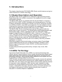
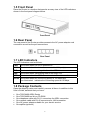
1.5 Front Panel
Place the Router in a location that permits an easy view of the LED indicators
shown in the front panel diagram below.
Front Panel
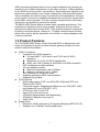
1.6 Rear Panel
The rear panel of the Router provides access to the AC power adapter cord
connection as well as the port connections.
Rear Panel
1.7 LED Indicators
The LED Indicators read as follows:
PWR
Illuminated when the unit is powered on.
LINK
Illuminated when the device is connected to LAN port(s).
TXD
Illuminated when receiving data from the ADSL line.
RXD
Illuminated when transmitting data to the ADSL line.
ADSL
Illuminated when the ADSL transceiver is in Showtime mode.
10/100
Illuminated when the connecting speed at 100 Mbps and
non-illuminated indicates the connecting speed at 10 Mbps .
1.8 Package Contents
Open the shipping carton and carefully remove all items. In addition to this
User's Guide, ascertain that you have:
• One TW-EA400 ADSL Router
• One TW-EA400 tool kit on CD-ROM
• One telephone cable with RJ-11 connectors for ADSL connection
• One network cable with RJ-45 connectors for LAN connection
• One AC power adapter suitable for your electric service
• One splitter (optional)

9
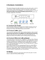
2 Hardware Installation
This section discusses the cable connections you will need to make in order to
use the Router. When selecting the location for the Router, allow room to
access the connections on the rear panel. You will want to place the Router so
that you will be able to see the LED indicators on the front panel.
It may be convenient for you locate the Router near the PC you intend to use
for initial configuration of the Router.
2.1 Connect the Power
Insert the Power Adapter cord into the power receptacle located on the rear
panel of the Router and plug the adapter into a nearby power source. You
should see the Power LED indicator light up and remain lit.
2.2 Connect ADSL Line
You can use the twisted-pair ADSL cable (standard telephone cable) included
with the Router to connect to your telephone line. Simply plug one end of the
cable into the LINE port (RJ-11 receptacle) on the rear panel of the Router and
insert the other end into the wall jack. This connection provides the link
between the Router and the ISPs network including access to the Internet.
2.3 Connect Ethernet LAN to Router
The Router may be connected to any 10/100BASE-T Ethernet LAN or Ethernet
concentrating device. Connection to an Ethernet concentrating device such as
a switch or hub should use standard twisted-pair cable with RJ-45 connectors.
The dedicated RJ-45 port on the Router are a crossed (MDI-X) connection
ports. Follow standard Ethernet guidelines when deciding what type of cable to
use to make this connection.
Use straight-through cable when connecting the Router to a normal (MDI-X)
port on a switch or hub. Use crossed cable when connecting it to an uplink
(MDI-II) on a hub or switch. When connecting the Router directly to a PC or
server use a straight-through cable. A valid connection will be indicated by the
Link LED indicator corresponding to the connected port.
2.4 Reset
The TW-EA400 comes with a reset button built into the rear panel. Use this
button to restore the factory default settings.

10
3. System Requirements
• Pentium Ⅱ 233 MHz processor minimum
• 32 MB RAM minimum
• 20 MB of free disk space minimum
• Etherne Network Interface Controller (NIC) RJ45 Port
• Internet Browse

11
4. Software Installation
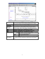
4.1 PC TCP/IP Settings
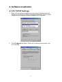
1. Right click the Network Neighborhood then select Properties. Network
dialog box would pop up. Under Configuration tab select TCP/IP->xxxxx,
where xxxxx is name of the network adapter. Click Properties.
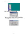
2. Click IP Address tab. Select “Obtain an IP Address automatically” and
then click OK.

12
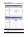
3. Select Run item from Start.
4. Enter winipcfg in the text field and then click OK.
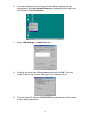
5. Select the adapter from pull-down list. Press Release All and then Renew
All to get the information of adapter. If you could not obtain the related
information, go back to step 2 to indicate the default gateway as
192.168.0.254 and then go through step3 to5 again.

13
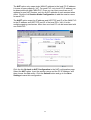
6. You must uncheck the Proxy server function before logining the web
configuration. Highlight Internet Explorer on desktop and then right-click
your mouse to select Properties.
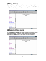
7. Select LAN Settings in Connections tab.
8. Uncheck the check box of Proxy server and then click OK. (You may
enable Proxy server function after logout if you need to use it.)
9. Type the default IP address 192.168.0.254 the address bar of the browser
to open web configuration.

14
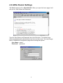
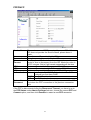
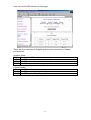
4.2 ADSL Router Settings
TW-EA400 default’s IP is 192.168.0.254. When you open the home page it will
ask you for User Name and Password.
Type the User Name and Password then click Ok button. The default login
name and password for administrator and user are the same. You may change
them in Password Configuration page after entering the system.
User Name : admin
Password :password

15
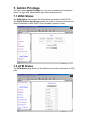
5. Status
The links under the Status column are associated to the pages that represent
the status of system and interfaces.
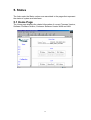
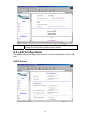
5.1 Home Page
The Home page displays the related information of current Firmware Version,
Software Firmware Version, Customer Software Version WAN and LAN.

16
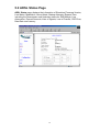
5.2 ADSL Status Page
ADSL Status page displays the information of Showtime Firmware Version,
Line Status, Modulstion, Annex Mode, Startup Attempts, Elapsed Time
including the Downstream and Upstream status for SNR Margin, Line
Attenuation, Errored Seconds, Loss of Signals, Loss of Frames, CRC Error,
Data Rate and Latency.

17
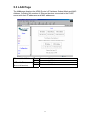
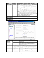
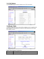
5.3 LAN Page
The LAN page displays the ADSL Router’s IP Address, Subnet Mask and MAC
Address. Including the number of Ethernet devices connected to the DHCP
server with their IP addresses and MAC addresses.
UP
Connected Mode
Ethernet Link Status
DOWN
Disconnected Mode
UP
Connected Mode
USB Link Status
(Reserved function)
DOWN
Disconnected Mode

18
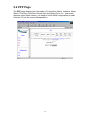
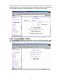
5.4 PPP Page
The PPP page displays the information of Connection Name, Interface, Mode,
Status, Pkts Sent, Pkts Revd, Bytes Sent and Bytes Revd. If a * (star mark)
appears under Mode column, you need to check WAN configuration to make
sure the VC has the correct encapsulation.

19
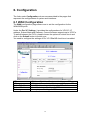
6. Configuration
The links under Configuration column are associated to the pages that
represent the configurations of system and interfaces.
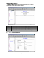
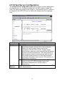
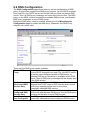
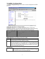
6.1 WAN Configuration
The WAN configuration page allows user to set the configuration for the
WAN/ADSL ports.
Under the Per VC Settings, it provides the configurations for VPI/VCI, IP
address, Subnet Mask and Gateway. Current firmware supports up to 8 PVCs.
To switch between the PVCs, please choose the options of virtual circuit and
click on the Submit button to switch over.
You need to configure the settings of Per VC if Per VC check box is enabled.
VPI
(VPI) Virtual Path Identifier is provided by your ISP.
VCI
(VCI) Virtual Channel Identifier is provided by your ISP.
Static IP Address
Static IP Address is provided by your ISP.
Subnet Mask
Subnet Mask is provided by your ISP.
Gateway
Gateway is provided by your ISP.

20
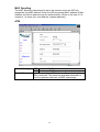
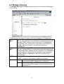
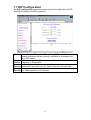
MAC Spoofing
The MAC Spoofing is developed to solve the scenario when the ISP only
recognizes one MAC address. Enter the ISP-recognized MAC address in Mac
Address text field to pass through the authentication. (Refer to the step 3-5 in
chapter 4.1 to know your mac address (adapter address)).
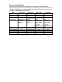
ATM
UBR
Undefined Bit Rate.
Service Category
CBR
Continuous Bit Rate.
Bandwidth
Set the bandwidth of ATM. It takes effect only when the
CBR is selected. The maximum available bandwidth is
from the upstream data rate of ADSL status page.
Page is loading ...
Page is loading ...
Page is loading ...
Page is loading ...
Page is loading ...
Page is loading ...
Page is loading ...
Page is loading ...
Page is loading ...
Page is loading ...
Page is loading ...
Page is loading ...
Page is loading ...
Page is loading ...
Page is loading ...
Page is loading ...
Page is loading ...
Page is loading ...
Page is loading ...
Page is loading ...
Page is loading ...
Page is loading ...
Page is loading ...
Page is loading ...
Page is loading ...
Page is loading ...
Page is loading ...
Page is loading ...
Page is loading ...
-
 1
1
-
 2
2
-
 3
3
-
 4
4
-
 5
5
-
 6
6
-
 7
7
-
 8
8
-
 9
9
-
 10
10
-
 11
11
-
 12
12
-
 13
13
-
 14
14
-
 15
15
-
 16
16
-
 17
17
-
 18
18
-
 19
19
-
 20
20
-
 21
21
-
 22
22
-
 23
23
-
 24
24
-
 25
25
-
 26
26
-
 27
27
-
 28
28
-
 29
29
-
 30
30
-
 31
31
-
 32
32
-
 33
33
-
 34
34
-
 35
35
-
 36
36
-
 37
37
-
 38
38
-
 39
39
-
 40
40
-
 41
41
-
 42
42
-
 43
43
-
 44
44
-
 45
45
-
 46
46
-
 47
47
-
 48
48
-
 49
49


Ask a question and I''ll find the answer in the document
Finding information in a document is now easier with AI
Related papers
Other documents
-
Sitecom LN-118UK Datasheet
-
 LaToscana SHOWER2CP Installation guide
-
Mercury Asus RT-N56U Dual-Band Gigabit Wireless-N Router Operating instructions
-
Digitus DN-50031 User manual
-
D-Link DSL-500 Quick start guide
-
Abocom AR3500 User manual
-
Zonet ZEW3002 Quick Installation Manual
-
 Dynalink ALE800 User manual
-
Intenso 3413770 Datasheet
-
 MicroNet Technology SP3367N User manual


