2
Important Information
Precautions: Please read this manual carefully before
using your NP-02HD and keep the manual handy for future
reference.
The NP-02 (projector head), NP-24LU01 / NP-20LU01 /
NP-18LU01 (light module), NP-NC2402ML / NP-NC2002ML
/ NP-NC1802ML (projector unit) are called the “projector”
and the NP-90MS02 (integrated media server) is called the
“media block” or “IMB” in this manual.
• DLP (Digital Light Processing), DLP Cinema and DLP
Cinema logo are trademarks of Texas Instruments.
• Microsoft, Windows and Internet Explorer are either reg-
istered trademarks or trademarks of Microsoft Corporation
in the United States and/or other countries.
• Mozilla and Firefox are either registered trademarks or
trademarks of the Mozilla Foundation in the United States
and/or other countries.
• Oracle and Java are registered trademarks of Oracle
and/or its affiliates.
• Linux is a registered trademark of Linus Torvalds in the
United States and/or other countries.
• Other product names and logos mentioned in the user’s
manual may be the trademarks or registered trademarks
of their respective holders.
• The display screens and illustrations shown in this man-
ual may differ slightly from the actual ones.
• GPL/LGPL Software Licenses
•
The product includes software licensed under GNU
• General Public License (GPL), GNU Lesser General
Public License (LGPL), and others.
•
For more information on each software, see “readme.pdf”
inside the “about GPL&LGPL” folder on the supplied
CD-ROM.
WARNING
TO REDUCE THE RISK OF FIRE OR ELECTRIC SHOCK,
DO NOT EXPOSE THIS APPLIANCE TO RAIN OR
MOISTURE.
CAUTION
TO PREVENT ELECTRIC SHOCK, DO NOT OPEN TOP
COVER. NO USER SERVICEABLE PARTS INSIDE.
This symbol warns the user that uninsulated
voltage within the unit may have sufficient
magnitude to cause electric shock. Therefore,
it is dangerous to make any kind of contact
with any part inside of this unit.
This symbol alerts the user that important lit-
erature concerning the operation and mainte-
nance of this unit has been included. Therefore,
it should be read carefully in order to avoid any
problems.
Laser Safety Caution
This product is classied as Class 1 of IEC60825-1 Third
edition 2014. This product is classied as RG3 of IEC62471-5
First edition 2015. This product is classied as RG3 of
IEC62471:2006.(for USA). Obey the laws and regulations of
your country in relation to the installation and management
of the device.
CAUTION
Use of controls or adjustments of procedures other than
those specied herein may lead to hazardous laser radi-
ation exposure.
• Hazardous optical radiation is emitted from this product,
RG3 IEC 62471:2006. (for USA).
• No direct exposure to the beam shall be permitted, RG3
IEC 62471-5:2015.
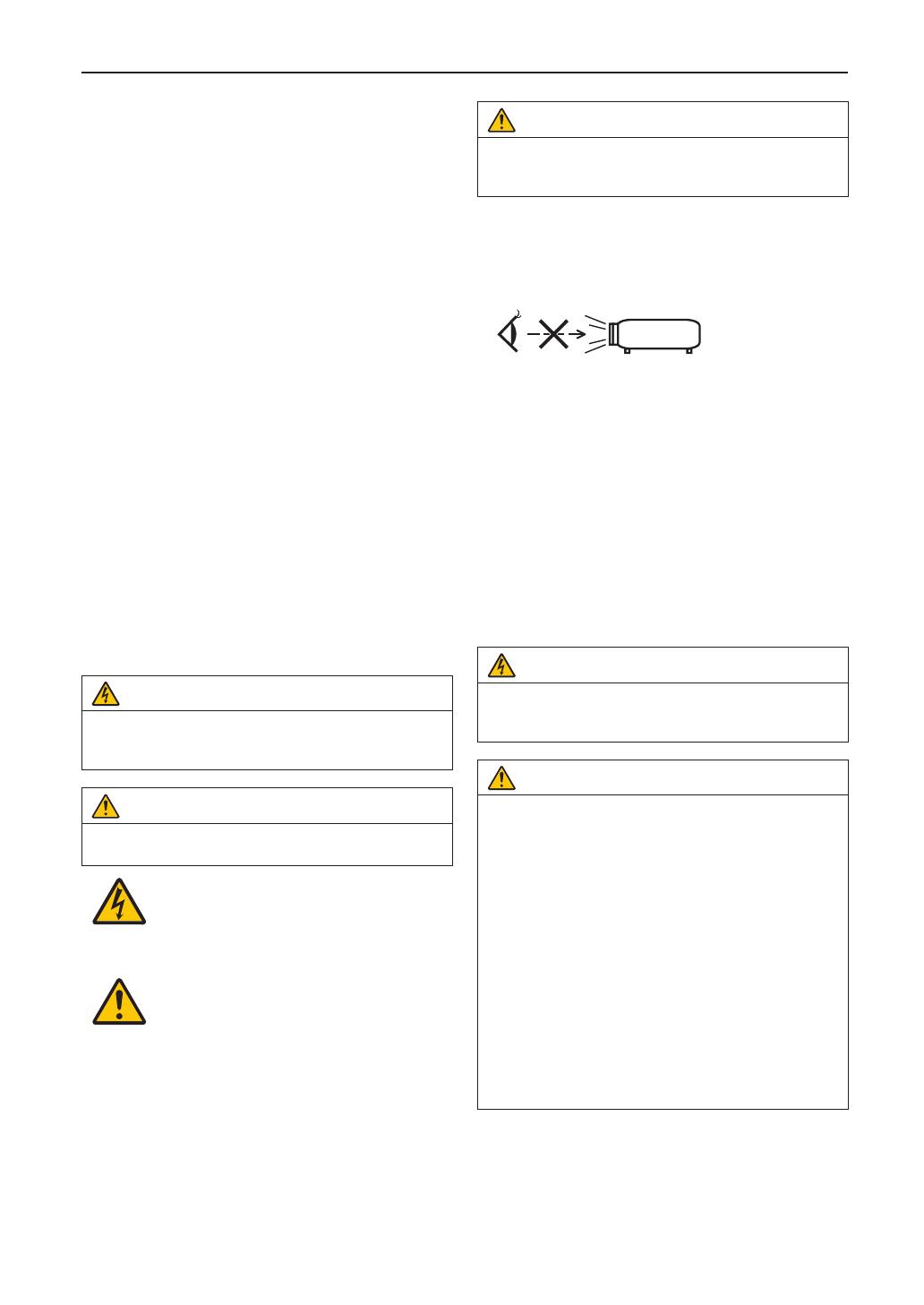
• Do not look into the lens while the projector is on. Serious
damage to your eyes could result.
• Keep any items such as magnifying glass out of the light
path of the projector. The light being projected from the
lens is extensive, therefore any kind of abnormal objects
that can redirect light coming out of the lens, can cause
unpredictable outcome such as re or injury to the eyes.
• When turning on the projector, ensure that nobody is fac-
ing towards the lens in the path of the light emitted from
the laser.
• This product can only be operated in theaters by speci-
ed personnel. Customers should not operate this
product.
Machine Noise Information Regulation - 3. GPSGV,
The highest sound pressure level is less than 70 dB (A) in
accordance with EN ISO 7779.
WARNING
This equipment is compliant with Class A of CISPR 32.
In a residential environment this equipment may cause
radio interference.
CAUTION
• In order to reduce any interference with radio and tele-
vision reception use a signal cable with ferrite core
attached. Use of signal cables without a ferrite core
attached may cause interference with radio and televi-
sion reception.
• This equipment has been tested and found to comply
with the limits for a Class A digital device, pursuant to
Part 15 of the FCC Rules. These limits are designed
to provide reasonable protection against harmful
interference when the equipment is operated in a
commercial environment. This equipment generates,
uses, and can radiate radio frequency energy and, if
not installed and used in accordance with the installa-
tion manual, may cause harmful interference to radio
communications. Operation of this equipment in a
residential area is likely to cause harmful interference
in which case the user will be required to correct the
interference at his own expense.


