NEC NC3541L Installation guide

Type
Installation guide

This manual is also suitable for

NC3541L
NC2041L
NP-NC3541L, NP-NC2041L
DLP Cinema Projector Installation and Adjustment NEC Display Solutions, Ltd. Manual (This document) describes the
procedures to install, adjust and maintain the projector and peripheral devices. For safe and correct installation, adjustment
and use of this projector, carefully read this document before location assessment and installation.
Refer to the operation manuals of the applicable products for basic operation and remarks of the projector. This document
expects the readers who have basic knowledge about projector installation. After reading, please keep this document under
care of the company which installed or adjusted the projector.
The product name used in this manual
In this manual, the device name is written as listed below. If the function has difference by devices, the product name is
written in the text.
NC3541L / NC2041L Projector
NP-90MS01 / NP-90MS02 Media block or IMS
Digital Cinema Communicator v2 DCC
Important Information
Please read this manual carefully before using your
NC3541L/NC2041L and keep the manual handy for
future reference. The NC3541L/NC2041L (projector
unit) is called the “projector”, and the NP-90MS01/
NP-90MS02 (integrated Media server) is called the
“media block” or “IMB” in this manual.
(for USA)
4
Important Information
WARNING
This equipment is compliant with Class A of CISPR 32. In
a residential environment this equipment may cause radio
interference.
CAUTION
In order to reduce any interference with radio and tele-
vision reception use a signal cable with ferrite core
attached. Use of signal cables without a ferrite core
attached may cause interference with radio and televi-
sion reception.
This equipment has been tested and found to comply
with the limits for a Class A digital device, pursuant to
Part 15 of the FCC Rules. These limits are designed to
provide reasonable protection against harmful interfer-
ence when the equipment is operated in a commercial
environment. This equipment generates, uses, and can
radiate radio frequency energy and, if not installed and
used in accordance with the installation manual, may
cause harmful interference to radio communications.
Operation of this equipment in a residential area is
likely to cause harmful interference in which case the
user will be required to correct the interference at his
own expense.
WARNING
THE END USER IS NOT ALLOWED TO OPEN OR MOD-
IFY THE PRODUCT.
NO USER SERVICEABLE PARTS.
MAINTENANCE AND SERVICE OF THE PRODUCT IS
ONLY TO BE HANDLED BY NEC AUTHORIZED
TECHNICIANS.
Important Safeguards
These safety instructions are to ensure the long life of your
projector and to prevent fire and shock. Please read them
carefully and heed all warnings.
Installation
1. Do not point the projection beam toward other people or
reflective objects.
2. Consult your dealer for information about transporting
and installing the projector. Do not attempt to transport
and install the projector yourself. The projector must be
installed by qualified technicians in order to ensure
proper operation and reduce the risk of bodily injury.
3. Place the projector on a flat, level surface in a dry area
away from dust and moisture. Do not put the projector on
its side when the Laser is on. Doing so may cause dam-
age to the projector.
4. Do not place the projector in direct sunlight, near heaters
or heat radiating appliances.
5. Exposure to direct sunlight, smoke or steam could harm
internal components.
6. Handle your projector carefully. Dropping or jarring your
projector could damage internal components.
7. To carry the projector, a minimum of six persons are
required.
8. Do not hold the lens part with your hand. Otherwise the
projector may tumble or drop, causing personal injury.
9. Do not place heavy objects on top of the projector.
10. Turn off the projector, and disconnect the power cable
before moving the projector.
For C2 connection, turn off the projector, shut down the
AC power to the projector and the light using a circuit
breaker. Disconnect the cables between devices and the
light before moving the projector.
11. Do not install and store the projector in the below circum-
stances. Failure to do so may cause of malfunction.
In powerful magnetic fields
In corrosive gas environment
Outdoors
12. If you wish to have the projector installed on the ceiling;
Do not attempt to install the projector yourself.
The projector must be installed by qualified techni-
cians in order to ensure proper operation and reduce
the risk of bodily injury.
Install the breaker in a location that is easy to reach by
hand.
In addition, to prevent ceiling collapse, the ceiling
should be able to support total weight of 177kg (pro-
jector weight of 169kg, lens weight of 8kg) for an
extended period of time, and the installation must be
in accordance with any local building codes.
Please consult your dealer for more information.
Refer to “2-2-1. Installing the Projector on the Ceiling”
(page 40) for details on the attachment positions when
installing on the ceiling.
WARNING
1. Do not use the projector with the supplied lens cap or
equivalent while the projector is operating. This may
cause the lens cap to heat up and deform or melt.
2. Do not place any objects, which are easily affected by
heat, in front of the projector lens. Doing so could lead
to the object melting from the heat that is emitted from
the light output.
5
Important Information
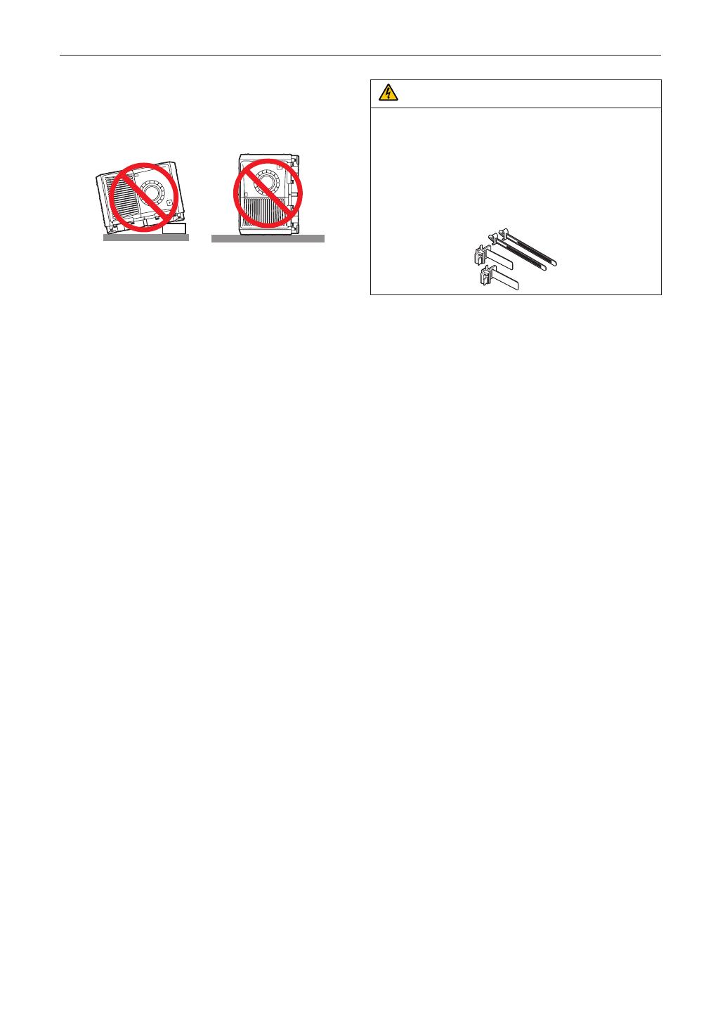
It is possible to vertically set up this device at 360 degrees.
However, please do not set up the main part of the device
slanted to the left or right because it may result in
malfunctions.
Power Supply
1. Consult your dealer for installing the power cable to the
projector. DO NOT install the power cable by yourself.
Doing so may cause a fire or electric shock.
The projector is so designed that it operates with the
power supply voltage described below.
For C1 connection
(When the AC power to the projector power supply and
the light power supply is provided by a single cable)
AC 200V-240V single phase 50/60Hz
For C2 connection
(When the AC power to the projector power supply and
the light power supply is provided by separate cables)
AC 200V-240V single phase 50/60Hz (projector power
supply)
AC 200V-240V single phase 50/60Hz (light power
supply)
Ensure that your power supply fits this requirement
before attempting to use your projector.
2. The power cable is not included with the projector. Use a
power cable that meets the standards and power supply
voltage of the country where you are using the projector.
Refer to “2-3. Selecting the Power Cable for C2 Connec-
tion (English)” for details.
3. Handle the power cable carefully. A damaged or frayed
power cable can cause electric shock or fire.
Do not bend or tug the power cable excessively.
Do not place the power cable under the projector, or
any heavy object.
Do not cover the power cable with other soft materials
such as rugs.
Do not heat the power cable.
4. Placing the power cable and the signal cable closely to
each other can cause beat noise. If this happens, keep
the two separated so that beat noise is not generated.
Beat noise is corruption of the picture often seen as a
rolling band moving through the image.
5. Do not touch the projector during a thunder storm. Doing
so can cause electrical shock or fire.
6. When installed on the ceiling, install the breaker in a loca-
tion that is easy to reach by hand.
CAUTION
The power cable stopper (shown in below) is supplied with
this projector.
To prevent the power cable from coming loose, make sure
that all the prongs of the power cable are fully inserted into
the AC IN terminal of the projector before using the power
cable stopper to fix the power cable. A loose contact of the
power cable may cause a fire or electric shock. For using
the power cable stopper, refer to the user’s manual.
Fire and Shock Precautions
1. Ensure that there is sufficient ventilation and that vents
are unobstructed to prevent potentially dangerous con-
centrations of ozone and the build-up of heat inside your
projector. Allow at least 24 inches (60 cm) of space
between your projector and a wall. In particular, clear a
space of 26.7 inches (70 cm) or more in front of the air
outlet on the rear surface and 12 inches (30 cm) or more
on the upper part of the projecter body. (See page 24)
2. Prevent foreign objects such as paper clips and bits of
paper from falling into your projector. Do not attempt to
retrieve any objects that might fall into your projector. Do
not insert any metal objects such as a wire or screwdriver
into your projector. If something should fall into your pro-
jector, shut down the AC power to the projector immedi-
ately and have the object removed by a qualified service
person.
For C2 connection, turn off the projector, shut down the
AC power to the projector and the light using a circuit
breaker, and contact your dealer/distributor.
3. Turn off the projector, shut down AC power by using a
circuit breaker and contact qualified service personnel
under the following conditions. For C2 connection, turn
off the projector, shut down the AC power to the projector
and the light using a circuit breaker, and contact your
dealer/distributor for a repair.
When the power cable or plug is damaged or frayed.
If liquid has been spilled into the projector, or if it has
been exposed to rain or water.
If the projector does not operate normally when you fol-
low the instructions described in this user’s manual.
If the projector has been dropped or the cabinet has
been damaged.
If the projector exhibits a distinct change in perfor-
mance, indicating a need for service.
4. When using a LAN cable:
For safety, do not connect to the connector for peripheral
device wiring that might have excessive Voltage.
6
Important Information
Cleaning
1. Shut down AC power by using a circuit breaker before
cleaning.
For C2 connection, turn off the projector, shut down the
AC power to the projector and the light using a circuit
breaker.
2. Clean the cabinet periodically with a cloth. If heavily
soiled, use a mild detergent. Never use strong deter-
gents or solvents such as alcohol or thinner.
3. Use a blower or lens paper to clean the lens, and be
careful not to scratch or mar the lens.
4. Do not handle the projector and the power cable with wet
hands. Doing so can cause electrical shock or fire.
CAUTION
1. Do not shut down AC power to the projector under the
following conditions.
Doing so can damage the projector.
While projecting images
While cooling after the power is turned off.
(The STATUS indicator LED blinks in orange while
the fan is rotating, and “cooling...” is displayed on
the LCD screen. )
- When using the NP-90MS01/NP-90MS02: 100
seconds
During IMB Operation (if the projector is not in
standby state)
2. Do not turn of the AC power for 90 seconds after the
Laser is turned on and while the POWER indicator is
blinking green. Doing so could cause premature Laser
failure.
3. Keep hands away from the lens mounting portion while
the lens shift is in operation. Failure to do so could
result in fingers being pinched between the cabinet
and lens cover.
4. When main body is damaged, cooling fluids may come
out of internal part. DO NOT touch and drink the cool-
ing fluid.
When the cooling fluids are swallowed or contacted
with your eyes, please consult with doctors
immediately.
Caution on Carrying the Projector/Handling the Optional
Lens
When installing/removing a lens, shut down the AC power to
the projector.
When shipping the projector with the lens, remove the lens
before shipping the projector. Always attach the dust
cap to the lens whenever it is not mounted on the projector.
The lens and the lens shift mechanism may encounter dam-
age caused by improper handling during transportation.
Handling the Battery
Take care when handling the battery, as it could cause fire,
injury, or damage to surrounding objects.
- Do not short out, dismantle, or place batteries in a fire.
Dispose of used batteries according to your local
regulations.
There is a battery mounted on the electronic circuit board
within the main unit. When disposing of the main unit, do
not dismantle the device or remove the internal circuit
board, and contact the shop where you purchased the
product or your local government agency.
Peripheral Devices and Connecting Cables
Use shielded cables for the cables connecting the IMB with
peripheral devices (GPI, GPO, AES cables). If you use a non-
shielded cable, there is a risk that radio interference may
occur.
WARNING TO CALIFORNIA RESIDENTS:
Handling the cables supplied with this product will
expose you to lead, a chemical known to the State of Cali-
fornia to cause birth defects or other reproductive harm.
WASH HANDS AFTER HANDLING
Light Module
1. A light module containing multiple laser diodes is
included in the product as the light source.
2. These laser diodes are sealed in the light module. No
maintenance or service is required for the performance
of the light module.
3. End user is not allowed to replace the light module.
4. Contact qualified distributor for light module replace-
ment and further information.
7
Important Information
Disposing of your used product
EU-wide legislation as implemented in each
Member State requires that used electrical and
electronic products carrying the mark (left) must
be disposed of separately from normal house-
hold waste.
This includes projectors and their electrical
accessories. When you dispose of such prod-
ucts, please follow the guidance of your local
authority and/or ask the shop where you pur-
chased the product.
After collecting the used products, they are
reused and recycled in a proper way. This effort
will help us reduce the wastes as well as the
negative impact to the human health and the
environment at the minimum level.
The mark on the electrical and electronic prod-
ucts only applies to the current European Union
Member States.
For EU: The crossed-out wheeled bin implies
that used batteries should not be put to the gen-
eral household waste! There is a separate col-
lection system for used batteries, to allow proper
treatment and recycling in accordance with
legislation.
According the EU directive 2006/66/EC, the bat-
tery can’t be disposed improperly. The battery
shall be separated to collect by local service.
For questions relating to unclear points or repairs
Contact your dealer or the following support branch for ques-
tions relating to unclear points, malfunctions and repairs of
the product.
In Europe
Company Name: NEC Display Solutions Europe GmbH
Address: Landshuter Allee 12-14, D-80637 Munichi,
Germany
Telephone: +49 89 99699 0
Fax Line: +49 89 99699 500
Email Address: [email protected]
WEB Address: http://www.nec-display-solutions.com
In North America
Company Name: NEC Display Solutions of America, Inc.
Address: 500 Park Boulevard, Suite 1100 Itasca, Illinois
60143, U.S.A.
Telephone: +1 800 836 0655
Fax Line: +1 800 356 2415
Email Address: pjtechsupport@necdisplay.com
WEB Address: http://www.necdisplay.com/
In China
Company Name: NEC Solutions (China) Co., Ltd.
Address: Rm 1903, Shining Building, 35 Xueyuan Rd,
Haidian District Beijing 100191, P.R.C.
Telephone: +8610-4008-900-678
Email Address: [email protected]
In Hong Kong and Taiwan
Company Name: Strong Westrex, Inc.
Address: Room 4108 China Resources Building, No. 26
Harbour Road, Wanchai, Hong Kong
Telephone: +852 2827 8289
Fax Line: +852 2827 5993
Email Address: [email protected]
In South Korea
Company Name: Hyosung ITX Co., Ltd.
Address: 1F, Ire Building, 2, Yangpyeong-dong 4-ga,
Yeongdeungpo-gu, Seoul, Korea 150-967
Telephone: +82-2-2102-8591
Fax Line: +82-2-2102-8600
Email Address: [email protected]
WEB Address: http://www.hyosungitx.com
In Australia and New Zealand
Company Name: NEC Australia Pty Ltd
Address: 26 Rodborough Road Frenchs Forest NSW 2086
Telephone: 131 632 (from anywhere in Australia)
Email Address: [email protected]
WEB Address: http://www.nec.com.au
In Thailand, Singapore, Malaysia, Indonesia and
Philippines
Company Name: Goldenduck International Co., Ltd.
Address: 65 Soi Phutthamothon Sai 1, 21 Bangramad,
Talingchan, Bangkok, Thailand 10170
Telephone: +66-2887-8807
Fax Line: +66-2887-8808
Email Address: contact@goldenduckgroup.com
Label A : Risk Group / Lamp Safety Label
Label B : Laser Explanatory Label
Label C : NP-NC3541L
Label C : NP-NC2041L
Label D
• The below table describes the radiation range of emitted light by the projector that is classified as Risk Group 3
(RG3) of IEC62471-5 First edition 2015.
• The below table describes the radiation range of emitted light by the projector that is classified as Risk Group 3
(RG3) of IEC62471:2006.(for USA).
• Please keep within bounds for installing the projector.
Install a barrier for preventing human eyes from entering the RG3 area. For the barrier installation position, keep
horizontal safety zone over 1.5m from the RG3 area. In case to install the projector over head, keep over 3m
distance at least between the floor surface and the RG3 area.
Operators shall control access to the beam within the hazard distance or install the product at the height that will
prevent exposures of spectatorseyes within the hazard distance.
Lens
RG3
HD (m)
Screen size (m)
H V
NC
-
50LS12Z
Wide 6.0 5.31 2.80
Tele 8.0 4.82 2.54
NC
-
50LS14Z
Wide 7.0 5.38 2.84
Tele 9.5 5.14 2.71
NC
-
50LS16Z
Wide 7.0 4.83 2.55
Tele 9.0 4.09 2.16
NC
-
50LS18Z
Wide 7.0 4.38 2.31
Tele 11.0 4.07 2.15
NC
-
50LS21Z
Wide 8.0 4.10 2.16
Tele 13.0 3.94 2.08
L2K-30ZM
Wide 11.0 4.07 2.15
Tele 16.0 4.10 2.16
Lens
RG3
HD (m)
Screen size (m)
EHv
H V
NC
-
50LS12Z
Wide 6.0 5.31 2.80 12
Tele 8.0 4.82 2.54 16
NC
-
50LS14Z
Wide 7.0 5.38 2.84 14
Tele 9.5 5.14 2.71 19
NC
-
50LS16Z
Wide 7.0 4.83 2.55 14
Tele 9.0 4.09 2.16 18
NC
-
50LS18Z
Wide 7.0 4.38 2.31 14
Tele 11.0 4.07 2.15 19
NC
-
50LS21Z
Wide 8.0 4.10 2.16 16
Tele 13.0 3.94 2.08 22
L2K-30ZM
Wide 11.0 4.07 2.15 20
Tele 16.0 4.10 2.16 22
NC3541L
(IEC62471-5 First edition 2015) (IEC62471:2006 (for USA)
NC2041L
(IEC62471-5 First edition 2015) (IEC62471:2006 (for USA)
Lens
RG3
HD (m)
Screen size (m)
H V
NC
-
50LS12Z
Wide 4.8 4.25 2.24
Tele 6.4 3.83 2.02
NC
-
50LS14Z
Wide 5.6 4.31 2.27
Tele 7.5 4.08 2.15
NC
-
50LS16Z
Wide 5.6 3.86 2.04
Tele 7.1 3.25 1.71
NC
-
50LS18Z
Wide 5.6 3.50 1.85
Tele 8.7 3.23 1.71
NC
-
50LS21Z
Wide 6.4 3.28 1.73
Tele 10.3 3.13 1.65
L2K-30ZM
Wide 8.8 3.26 1.72
Tele 12.7 3.26 1.72
Lens
RG3
HD (m)
Screen size (m)
EHv
H V
NC
-
50LS12Z
Wide 4.8 4.25 2.24
12
Tele 6.4 3.83 2.02
16
NC
-
50LS14Z
Wide 5.6 4.31 2.27
14
Tele 7.5 4.08 2.15
19
NC
-
50LS16Z
Wide 5.6 3.86 2.04
14
Tele 7.1 3.25 1.71
18
NC
-
50LS18Z
Wide 5.6 3.50 1.85
14
Tele 8.7 3.23 1.71
19
NC
-
50LS21Z
Wide 6.4 3.28 1.73
16
Tele 10.3 3.13 1.65
22
L2K-30ZM
Wide 8.8 3.26 1.72
20
Tele 12.7 3.26 1.72
22
11
Important Information
CAUTION
Please heed all precaution for safety.
To install the projector
For planning the layout of the projector, make sure to take safety measures instructed on the installation manual.
In order to refuse danger, install either a wall outlet within easy reach for pulling out the power plug in emergency or a
device as a breaker to shut down the power supply to the projector.
Take safety measures preventing human eyes from entering the RG3 area.
Considering the installation place, select an appropriate lens and secure safety zone that is determined for each lens.
For operation on the powered projector as light adjustment, make sure appropriate safety measures have been taken.
Check the validity of taken security measures if appropriate safety zone based on the installed lens is secured. Periodi-
cally check the validity and keep these results.
Educate the administrator of the projector (operators) about safety before starting to operate the projector.
To use the projector
Instruct the administrator of the projector (operators) to perform inspections before powering on the projector. (Including
the safety check against emitted light by the projector)
Instruct the administrator of the projector (operators) to be in circumstances able to control the projector whenever the
projector is powered on for an emergency.
Instruct the administrator of the projector (operators) to keep the installation manual, user’s manual and inspection
records to a place where they can take these documents out easily.
Instruct them to clarify if the projector is conformed to standards of each country and region.
22
Introduction ......................................................................................................................................................................... 2
Important Information ........................................................................................................................................................ 3
Wichtige Informationen .................................................................................................................................................... 12
1. Before Setting Up Your Projector ............................................... 24
1-1. Clearance for Installing the Projector (English) ................................................................................................... 24
1-2. Freiraum bei der Projektorinstallation (Deutsch) ................................................................................................. 26
1-3. Selecting the lens unit ............................................................................................................................................ 28
1-3-1. Screen Type .................................................................................................................................................. 28
1-3-2. Calculating the lens zoom magnication to use ....................................................................................... 30
1-4. Carrying the projector ............................................................................................................................................ 32
1-5. Removing the Projector Covers ............................................................................................................................. 33
1-5-1. Removing and Mounting the Lens Cover .................................................................................................. 35
1-5-2. Removing and Mounting the Side Panel .................................................................................................... 37
1-5-3. Removing and Mounting the Filter Cover .................................................................................................. 37
2. Setting Up Your Projector .......................................................... 38
2-1. Setup Procedure ..................................................................................................................................................... 38
2-2. Projector Installation .............................................................................................................................................. 39
2-2-1. Installing the Projector on the Ceiling ....................................................................................................... 40
2-2-2. Tilt-Free Installation ..................................................................................................................................... 41
2-2-3. Terms for Preparation of Frames and Ceiling Hanging Brackets ............................................................ 41
2-3. Selecting the Power Cable for C2 Connection (English) ..................................................................................... 42
2-3-1. AC Power Work Specications ....................................................................................................................43
2-4. Auswahl des Netzkabels für Anschluss C2 (Deutsch) ........................................................................................ 45
2-4-1. Netzstrom-Spezikationen ..........................................................................................................................46
2-5. Connecting the power cable (English) .................................................................................................................. 48
2-5-1. Power supply construction specications ................................................................................................ 48
2-5-2. Procedure for connecting the power cable (C1 connection) ................................................................... 55
2-5-3. Procedure for connecting the power cable (C2 connection) ................................................................... 58
2-6. Anschließen des Netzkabels (Deutsch) ................................................................................................................ 63
2-6-1. Technische Daten zum Netzanschluss ..................................................................................................... 63
2-6-2. Anschluss des Stromkabels (Anschluss C1) ............................................................................................ 70
2-6-3. Anschluss des Stromkabels (Anschluss C2) ............................................................................................ 73
2-7. Mounting the Lens Unit .......................................................................................................................................... 78
2-8. Mounting the Option Board ................................................................................................................................... 82
2-8-1. Make the option board usable .................................................................................................................... 84
3. Projector Adjustment and Connecting ....................................... 86
3-1. Flow of Adjustment and Connecting ..................................................................................................................... 86
3-2. Recovering from Tamper Errors ............................................................................................................................. 87
3-2-1. Clearing tamper events ...............................................................................................................................88
3-3. Turning your Projector On...................................................................................................................................... 90
3-4. Setting the Date and Time in the Projector ........................................................................................................... 91
3-5. Setting the Projector Projection Method...............................................................................................................92
3-6. Adjusting the Lens ................................................................................................................................................. 93
3-6-1. Display the Test Pattern ............................................................................................................................... 93
3-6-2. Adjusting the Screen Angle ....................................................................................................................... 94
3-7. Connecting with the Image Input Port .................................................................................................................. 95
3-8. Connecting the Various Control Terminal ............................................................................................................. 96
4. LCD Menu .................................................................................. 97
4-1. List of Menu ............................................................................................................................................................. 97
4-1-1. When You Use the Service Personnel Menu ............................................................................................ 100
4-2. Title Select ............................................................................................................................................................. 101
4-2-1. Title select (Title Memory) ......................................................................................................................... 101
Table of Contents
23
Table of Contents
4-2-2. Test Pattern ................................................................................................................................................. 101
4-3. Conguration ........................................................................................................................................................ 102
4-3-1. Light Setup ................................................................................................................................................. 102
4-3-2. Lens Control ............................................................................................................................................... 102
4-3-3. Reset ........................................................................................................................................................... 103
4-3-4. Setup ........................................................................................................................................................... 105
4-3-5. Installation .................................................................................................................................................. 109
4-3-6. Memory ....................................................................................................................................................... 113
4-4. Title Setup ............................................................................................................................................................. 114
4-4-1. Preset Button .............................................................................................................................................. 114
4-5. Information ............................................................................................................................................................ 115
4-5-1. Light ............................................................................................................................................................ 115
4-5-2. AC Voltage................................................................................................................................................... 115
4-5-3. Preset Button .............................................................................................................................................. 115
4-5-4. Usage .......................................................................................................................................................... 116
4-5-5. Error Code .................................................................................................................................................. 116
4-5-6. Version ........................................................................................................................................................ 117
4-5-7. IP Address................................................................................................................................................... 117
4-5-8. Setup Date .................................................................................................................................................. 118
4-5-9. Option Status ............................................................................................................................................. 118
5. Appendix .................................................................................. 119
5-1. List of Registered Titles (when shipped from the factory) ................................................................................ 119
5-2. Error Code List ...................................................................................................................................................... 120
5-3. Remote Interlock Connector ................................................................................................................................ 128
5-4. Outline Drawing .................................................................................................................................................... 130
5-5. Index ...................................................................................................................................................................... 131
24
1. Before Setting Up Your Projector
1-1. Clearance for Installing the Projector (English)
Allow ample clearance between the projector and its surroundings as shown below.
Avoid installing the projector in a place where air movement from the HVAC is directed at the projector.
Heated air from the HVAC can be taken in by the projector’s intake vent. If this happens, the temperature inside the projector
will rise too high causing the over-temperature protector to automatically turn off the projectors power.
Example 1 – If there are walls on both sides of the projector.
60cm/12"
or greater
60cm/12"
or greater
NOTE
The drawing shows the proper clearance required for the front, back and top of the projector.
Example 2 – If there is a wall behind the projector.
(1) For floor installation:
70cm/27.6"
or greater
Lens
NOTE
The drawing shows the proper clearance required for the front, sides and top of the projector.
25
Before Setting Up Your Projector
(2) For ceiling mounting:
Lens
70cm/27.6"
or greater
30cm/12"
or greater
NOTE
• The drawing shows the proper clearance required for the front, sides, back and bottom of the projector.
• If suspending the projector 30 cm/12 inches away from the ceiling, allow ample clearance for all four sides and
the under the projector.
28
Before Setting Up Your Projector
1-3. Selecting the lens unit
This section provides guideline information on how to select the screen size, the projector mounting position, and the type of
lens unit that is appropriate for your presentation purposes. Multiple lens units are sold separately as options for this projector.
Select an appropriate lens unit according to the environment in which your projector is installed. Note that all descriptions
given in this manual assume the angle of projection is zero degrees. In the case of projection from an upper position or from
the left or right, it is necessary to calculate the width for the minimum projected image at a size larger than the screen size.
Width of minimum
Screen
Projected image
1-3-1. Screen Type
The following two types of screen masks can be used for the DLP Cinema Projector. Check the screen mask for your projector
for its type before selecting lens units, because types of lens units to be used on the projector and its settings depend upon
the type of screen mask you use.
Horizontal moving screen mask
Screen masks move horizontally to adjust the screen.
ScreenScreen mask Screen mask
29
Before Setting Up Your Projector
Vertical moving screen mask
Screen masks move vertically to adjust the screen.
Screen
Screen mask
Screen mask
30
Before Setting Up Your Projector
1-3-2. Calculating the lens zoom magnication to use
The lens zoom magnification required when installing the projector is calculated using the following method.
(1) Calculate the lens zoom magnification for SCOPE projection
(2) Calculate the lens zoom magnification for VISTA (FLAT) and HDTV projection
(3) Select the lens that satisfies the zoom magnification calculated in (1) and (2).
SCOPE projection:
Lens
magnification
=
Length of projection (L)
Screen width (W)
VISTA (FLAT)/HDTV projection:
Lens
magnification
=
Length of projection (L)
Screen width (W) × (4096 ÷ (Number of pixels per horizontal line × 2))
Note: Number of pixels per horizontal line: 1998 for VISTA (FLAT); 1920 for HDTV
Select a lens that meets the magnification requirement for SCOPE, VISTA (FLAT), and HDTV screen types.
Screen width (W)
Screen height (H)
Projector
Length of projection (L)
Screen
Length centerline
Centerlines
  • Page 1 1
  • Page 2 2
  • Page 3 3
  • Page 4 4
  • Page 5 5
  • Page 6 6
  • Page 7 7
  • Page 8 8
  • Page 9 9
  • Page 10 10
  • Page 11 11
  • Page 12 12
  • Page 13 13
  • Page 14 14
  • Page 15 15
  • Page 16 16
  • Page 17 17
  • Page 18 18
  • Page 19 19
  • Page 20 20
  • Page 21 21
  • Page 22 22
  • Page 23 23
  • Page 24 24
  • Page 25 25
  • Page 26 26
  • Page 27 27
  • Page 28 28
  • Page 29 29
  • Page 30 30
  • Page 31 31
  • Page 32 32
  • Page 33 33
  • Page 34 34
  • Page 35 35
  • Page 36 36
  • Page 37 37
  • Page 38 38
  • Page 39 39
  • Page 40 40
  • Page 41 41
  • Page 42 42
  • Page 43 43
  • Page 44 44
  • Page 45 45
  • Page 46 46
  • Page 47 47
  • Page 48 48
  • Page 49 49
  • Page 50 50
  • Page 51 51
  • Page 52 52
  • Page 53 53
  • Page 54 54
  • Page 55 55
  • Page 56 56
  • Page 57 57
  • Page 58 58
  • Page 59 59
  • Page 60 60
  • Page 61 61
  • Page 62 62
  • Page 63 63
  • Page 64 64
  • Page 65 65
  • Page 66 66
  • Page 67 67
  • Page 68 68
  • Page 69 69
  • Page 70 70
  • Page 71 71
  • Page 72 72
  • Page 73 73
  • Page 74 74
  • Page 75 75
  • Page 76 76
  • Page 77 77
  • Page 78 78
  • Page 79 79
  • Page 80 80
  • Page 81 81
  • Page 82 82
  • Page 83 83
  • Page 84 84
  • Page 85 85
  • Page 86 86
  • Page 87 87
  • Page 88 88
  • Page 89 89
  • Page 90 90
  • Page 91 91
  • Page 92 92
  • Page 93 93
  • Page 94 94
  • Page 95 95
  • Page 96 96
  • Page 97 97
  • Page 98 98
  • Page 99 99
  • Page 100 100
  • Page 101 101
  • Page 102 102
  • Page 103 103
  • Page 104 104
  • Page 105 105
  • Page 106 106
  • Page 107 107
  • Page 108 108

NEC NC3541L Installation guide

Type
Installation guide
This manual is also suitable for

Ask a question and I''ll find the answer in the document

Finding information in a document is now easier with AI