Page is loading ...

Tech WorksTM
“Making Specialized Communication Easy”
A Division of: United Communication Technology, Inc.
22347 La Palma Ave., Suite #107, Yorba Linda, CA 92887
Direct Line: 714-694-1040 Fax: 714-694-1041 Toll Free: 1-800-813-1080
Web site www.tech4people.com 2/15
IC-52B
DUAL CHANNEL
AUDIO INTERCOM AMPLIFIER
OPERATION AND INSTALLATION
MANUAL

2/15 Page 2 of 26
How to use this Manual
Those wishing to use one of the standard Configuration Templates, should first read the
Overview, and then proceed to the appropriate Configuration Template for your application.
The Setup, Adjustments section should also be read before installation.
For those users who wish to do their own engineering then all sections may be useful. You may
also wish to contact a Tech Works application engineer for assistance.
Table of Contents
Table of Contents…………………………………….
List of Illustrations……………………………….……
Overview…………………………………………….….
Specifications…………………………………………..
Functional Diagram and Explanation………………..
Mechanical Details….…………………………………
Front Panel controls and Indicators…….…………..
Rear Panel Connections.……………………………..
Main Board Jumper Options……...…………………..
Setup, Adjustments…………………………………….
Application Templates…………………………………..
Mounting Options……………………………………..…
Accessories………………………………………………
Page 2
Page 3
Page 4
Page 6
Page 5
Page 8
Page 9
Page 10
Page 13
Page 17
Page 21
Page 25
Page 26

2/15 Page 3 of 26
List of Illustrations:
Functional Diagram……………………………………....
Mechanical Drawings…………………………………....
Front View……..……………………………….………….
Rear View……………………………….…….…………...
Simplified Block Diagram…………………….…………..
PCB Jumper Location.……………………………….…..
General Configuration Template………………………...
Ticket/Drive-Through Window VOX application……….
Cath-Lab Application with Doctor Music………………..
Interview Application with Conversation Logging………
IC-52B-DM Desk Mount…………………….……………..
IC-52B-WM Single Wall Mount…………………………..
IC-52B-WM2 Dual Wall Mount……………..…………….
IC-52B-RM Rack Mount……………………..……………
IC-52B-RM2 Rack Mount…………………………………
Accessories………………………………………………..
Page 5
Page 8
Page 9
Page 10
Page 12
Page 13
Page 21
Page 22
Page 23
Page 24
Page 25
Page 25
Page 25
Page 25
Page 25
Page 26

2/15 Page 4 of 26
Overview
The IC-52B is the most versatile Audio Intercom ever built. Yet it is also the easiest to integrate
into your design. Configuration Templates support every common application. Follow the
Setup and you’re done. If there is not a template for your application, give us a call; we will be
pleased to assist you to configure the IC-52B into your design.
The audio quality of the IC-52B is superb. Noise and distortion are very low. Selectable
equalization optimizes voice communications. The Automatic Level Control assures optimum
performance. There are separate controls for Audio Level, and Reach. Once set, the Audio
Level remains constant over wide dynamic input range. The independent Reach Control allows
for optimized accommodation of the input signal level. The user may wander throughout the
room, and still be heard at a nearly constant level without any operator adjustments!
Hands-Free operation is easily achieved with the IC-52B. The selectable Voice Operation
(VOX) operates flawlessly. Electronic switching takes less than 3mS. Setup indicators make
adjustments easy
The IC-52B incorporates two selectable Notch-Filters to reduce acoustic feedback. One filter
has an optimized frequency range to compensate for poor room acoustics. The other has a
higher frequency range to reduce microphone to wall/glass resonance.
In every way the IC-52B is the Universal Audio Intercom Amplifier Solution. The logic interface
has a plethora of Inputs and Outputs. However standard functions require few wires. The
Indicators are comprehensive, yet a simple. The interface is fully configurable, with jumpers,
however common functions are preset. Audio controls are on the IC-52B front panel.
Line Level, 0dBm Outputs may be configured for Paging, Monitoring or Logging
Jumpers allow for Audio Signal Selection, and Keying
The Tech Works PA-BUSS Line Level Output is fully configurable.
Pre-emptive Music is accommodated using the Tech Works PA-402 Power Amplifier
Modular Construction makes the IC-52B ideal for integrated designs. The unit is small; mounting
is flexible, and easy. Power is from a Universal Plug-in D.C power adapter. All I/O is through
Euro-Style connectorized barrier strips.
The IC-52B has major improvements, over its predecessor:
Universal Microphone/Line Inputs
Phantom Power now 22 Volts Current Limited (used to be 10 Volts)
Gain Structure change; Rotary Microphone Gain Control, Trim-Pot Speaker Level
25 Volt, 10 Watt Speaker Outputs
Line Outputs, inbuilt, no Option PCB required
PA-BUSS Output Connector, Easy Connectivity to other Tech Works Products
Privacy Tone removed

2/15 Page 5 of 26
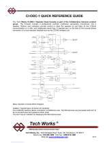
IC-52B Functional Diagram
Each audio path or channel has its own audio control section, which provides Automatic Level
Control, Amplifier Muting and other functions. These can be operationally assigned for specific
applications based on placement of removable jumpers inside the unit.
A two band notch filter is included to reduce feedback. These filters are shipped from the factory
disabled; they can be enabled by moving jumpers to the Remote or Operator Channel. Notch
filters must be set up in the field.
The Logic Control section provides the interface of the control contact inputs as well as the
audio control for muting audio signals depending on how the unit is configured. If it is configured
for full duplex then only muting is enabled. If the Call In feature is active, the logic controls the
tone interfaces to the Operator Speaker amplifier.
Configurable Line Level Outputs are provided for Paging, Monitoring or Logging
A PA-BUSS output may be used with a PA-402 Power Amplifier for Pre-emptive Music

2/15 Page 6 of 26
Specifications
General:
Dual Channel Universal Audio Intercom Amplifier
Inputs: R.F. and static electricity protected
Outputs: short circuit protected
Frequency Response: 250 Hz to 10 KHz
10-Watts RMS Sine Wave output, 25 Volts (Balanced)
Distortion at full voltage output < 1% T.H.D.
Power Supply Required: 24 Volts DC @ 2.2 Amps for full rated output
Unit is intended to use with class 2 power source (Sold Separately)
24 Volts D.C. 48-Watts Maximum
Microphone/Line Inputs:
Both Operator and Remote
Configured for a Microphone Level Input:
2000 Ohms Balanced
-76dBm or -60dBm (Selectable) minimum input (Balanced) for full rated output
Selectable Equalization - 3 settings optimized for voice communication
Selectable Phantom Power (22 Volts, Short Circuit Protected)
Configured for a Line Level Input:
2000 Ohms Balanced, 1000 Ohms Unbalanced
Balanced input -35dBm to +5dB or -20dBm to +20dB Accommodation range Un-
Balanced Input -30dBm to +10dB or -10dBm to +20dB Accommodation range
Speaker Outputs:
Both Operator and Remote
Balanced
25-Volts, 10-Watts (Maximum)
Line Level Outputs:
Transformer Isolated ~0dBM
Remote Microphone, after signal processing
May be keyed by control inputs
Mixed Output
Selectable summing of any of:
Remote Microphone, after signal processing
Operator Microphone, after signal processing
Call Tone
All signals may be keyed by control inputs

2/15 Page 7 of 26
PA-BUSS Output, signal pairs:
Configurable with internal jumper options
Power, 23 Volts, 350 Milli-Amps fold back current limited, short circuit current ~ 40MA
Line Level Output, Transformer Isolated ~0dBM
ALERT, indicates attention is requested
Automatic Level Control:
Operator and Remote
Greater then 40dB Automatic Level accommodation
Fast Attack, <10mS
Feed Forward Control, no ‘Pumping’
Independently adjustable Microphone Gain
Notch Filters
Selectable Channel: Operator; Remote; Not used
Notch Depth > 10dB
Two tandem frequency ranges: 250-1000Hz; 750-3000Hz
Voice Activation (VOX)
VOX setup indicator
Electronic Switching <3mS
Silent Switching, no Pops
Adjustable Recovery Delay
Call Tone
Uses Operator Speaker
Selectable
Continuous, or One Shot
Adjustable Level


2/15 Page 9 of 26
FRONT PANEL CONTROLS AND INDICATORS
IC-52B Front View
Power Indicator
Green when operating normally
Call Tone Level
Control trimpot, sets the level of the tone from the Operator speaker associated with a
‘Call’ button closure.
“OPERATOR” (Remote Microphone to Operator Speaker)
Active Indicator
Green: Remote Microphone is keyed, Operator Speaker Amplifier is ON
‘Reach’, Remote Microphone Gain
16 Position Switch, 3dB/step
Sets preamplifier sensitivity for Normal Microphone input level
‘Reach’ Level Indicator, Remote Microphone Level
Off, Microphone Off
Green, low input level
Green, flashing to Red, Normal Operation
Speaker Level
Control trimpot, sets the listening level from the Operator Speaker
Voice Activation
VOX Sensitivity trimpot, when fully CCW, VOX is disabled
VOX Setup Indicator, Green when Operator is listening, or muted,
Red when Operator is talking (See setup instructions)
Anti-VOX Trimpot (Negates inside Speaker Microphone acoustic coupling)
Notch Filters:
‘LO’ Band Notch Filter trimpot, 250 to 1000Hz
‘HI’ Band Notch Filter trimpot, 750Hz to 3000Hz
“REMOTE” (Operator Microphone to Remote Speaker)
Active Indicator
Green: Operator Microphone is keyed, Remote Speaker Amplifier is ON

2/15 Page 10 of 26
‘Reach’, Operator Microphone Gain
16 Position Switch, 3dB/step
Sets preamplifier sensitivity for Normal Microphone input level
‘Reach’ Level Indicator, Operator Microphone Level
Off, Microphone Off
Green, low input level
Green, flashing to Red, Normal Operation
Speaker Level
Control trimpot, sets the listening level from the Remote Speaker
REAR PANEL CONNECTIONS
OP MIC (-)
OP MIC (+)
OP SPKR (-)
COMMON
OP SPKR (+)
CHASSIS
+24VDC
COMMON
SUTOFF SW
COMMON
ACTIVATE SW
REM MIC (-)
REM MIC (+)
REM SPKR (-)
COMMON
REM SPKR (+)
PTT SW
VOX INHIBIT
CALL SW
REM ACTIVE
COMMON
OP ACTIVE
CALL
PA (-)
PA (+)
REM (+)
REM (-)
IC-52B Rear View
Audio I/O, Euro Style Barrier Strip
Operator Microphone/Line Input, Configurable, see Specifications, and Jumper Options
Operator Speaker Output
Remote Microphone/Line Input, Configurable, see Specifications, and Jumper Options
Remote Speaker Output
Page Output Line Level Output, after signal processing, ~0dBm
Remote Microphone Line Level Output, after signal processing, ~0dBm
PA-BUSS Output, RJ-45 Connector, signal pairs:
Power, 23 Volts, current limited, shared with IND PWR
Line Level Output, after signal processing, ~0dBm
ALERT, indicates attention is requested

2/15 Page 11 of 26
Control Inputs, Euro Style Barrier Strip, common sensing for Switches, or PLC
Switch Common
Shutoff (Lowest Priority) - Active low, momentary, or sustained, see below
Disables both Operator and Remote Speakers
(Overridden by “Activate”, “Push to Talk”)
Power on, quiescent state, Operator Shutoff
Activate - Active Low, momentary, or sustained
Overrides “Shut Off”,
Cancels Call Tone (Jumper Option)
Cause Privacy Tone to be sent (Jumper Option)
Push to Talk (PTT) - Active Low, momentary or sustained
Forces the Remote speaker on while depressed (Sustained)
Cancels “Call Tone” (Jumper Option)
Activates the Intercom if Inactive
VOX Inhibit - Active low, sustained
Defeats VOX while depressed,
Provides privacy to the Operator microphone, when using VOX
Call - Active low, momentary
Causes ‘Call Tone’ to be sent to the Inside speaker
Causes Call Light to flash
Indicator Outputs, Euro Style Barrier Strip
Open Collector Transistors, Common sensing for Indicators, or PLC V<30Volts, I<200MA
Common
Remote Active, Remote Microphone Keyed, low when Keyed
Operator Active, Operator Microphone is Keyed, low when Keyed
Call Indicator, flashes Low when Call Tone is present
Power, Euro Style Barrier Strip, connected in parallel with Barrel Connector
+24 Volts, DC
Power Supply Return
Chassis
Barrel Connector, two in Parallel
PJ-102A, center connector positive


2/15 Page 13 of 26
Jumper Options (Refer to the Block Diagram for Jumper Function)
OP PHANTOM
OFF ON
REM PHANTOM
OP MIC ON
SWITCHED
ALWAYS
REM MIC ON
SWITCHED
ALWAYS
NOTCH
FILTER
REMOTE MIC
OPERATOR MIC
CALL TONE
PA OUTPUT
AUDIO
ON OFF
ALERT
REM MIC ON
OP MIC ON
CALL TONE RUNNING
10 mS
200 mS
CHANGEOVER
DELAY
CALL TONE
CONTINUOUS
ONE CYCLE
OP SPKR ON
REM SPKR ON
SWITCHED
ALWAYS
MIC MIC
HI CUT
MED CUT
OP EQ
Tech Works
IC-52
HI CUT
MED CUT
REV- B-1
UNUSED
OPREM
SOURCES
REM EQ
REM GAIN OP GAIN
LO HI OFF ON LO HI
P16P17P18P19P20P21P12
P13
P6
P11
P5
P15 P14
P9 P8 P3 P2
P7
P10
P1
P4
IC-52B Main Board Jumper Locations
Control Functions Jumpers:
Change Tone Shutoff
The Call Tone is edge triggered by a Switch Closure
The Call Tone is Cancelled by the a PTT Switch Closure
The Call Tone may run a single cycle and Stop ONE CYCLE
Or Run continuously until the PTT switch is pressed CONTINUOUS
Change Over Delay
These Jumpers control the switching time from the Remote Speaker being active, to the
Remote Microphone turning on. When the Remote Speaker is also being used as the
Remote Microphone it is necessary to have a small delay or an acoustic pop will be heard at
the Operator position. The amount of delay is determined by experiment.
Delay:
~10mS, Normal for separate Microphone and Speaker 10mS
in a non-reverberant environment
Severe Reverberant Environment 200mS
Or Remote Speaker also being used as a Microphone

2/15 Page 14 of 26
Audio Input Jumpers:
Universal Microphone/Line Input both channels:
This input can accommodate a wide range Microphone or Line inputs
The Microphone Sensitivity is adjustable with the 16 Position Rotary Switch
With ~3db/Step for a 45 dB range
By using the Gain Switch, and Jumper options the total Range is -75dB to +20dB
The Signal is processed with an ALC, to assure the Output never exceeds 0dBm
Indicators allow the Microphone Gain to be adjusted to the optimal level
Phantom Power:
Terminating Resistors referenced to +22Volts, Current limited @ 7MA , ON
Terminating Resistors referenced to Common, OFF
Gain Range:
Input Gain reduced 15db, LO
Full Gain, HI
EQ Jumpers (Two):
Both Jumpers, upper position, lowest frequency Roll-off
(Used with most gooseneck and Hanging microphones)
Only MED CUT Jumper Upper Position, Medium frequency Roll-off
(Used with most flush mounted microphones)
Only HI CUT Jumper Upper Position, Highest frequency Roll-off
(Used with most Speakers used as a microphone)
Both Jumpers Lower Position, (Line Input)
~170Hz Roll-off, Sensitivity reduced to –35Bm for full Output
Note:
For a Balanced Line Level Input the LO Gain Position is also used
The Accommodation Range for full output is ~ -10dBm to +20dBm (With 10dB of Headroom)
Notch Filters
A Notch Filters are useful in Environment with one or two strong Resonant Modes
Examples are floor to ceiling modes, or small Room wall-to-wall modes
‘Notching out’ these resonances increases intelligibility, and reduces feedback
The Notch Filters may be used in either Channel, or not at all
Notch filters are shipped (default) in the Remote to Operator channel.
The factory settings are: LO, fully CCW, HI, Fully CW; the Notch Filters are essentially disabled

2/15 Page 15 of 26
Audio Switching Configuration Jumpers
The IC-52B has two Audio Channels, designated as
Remote Microphone to Operator Speaker and Operator Microphone to Remote Speaker
With all Signal Flow Jumpers in place, Half Duplex Operation is supported
Half Duplex Operation, the Microphone Inputs and Speaker Outputs are sequenced:
When the Operator is “Listening”:
The Remote Microphone is ON
The Operator Microphone is OFF
The Operator Speaker is ON
The Remote Speaker is OFF
When the Operator is “Talking”:
The Remote Microphone is OFF
The Operator Microphone is ON
The Operator Speaker is OFF
The Remote Speaker is ON
However, the control of the Microphones and Speakers are controlled by Jumpers
Any of these sections may always be ON
These ‘always’ selections are useful in implementing in implementing:
Always Listening, Push to Talk
Full Duplex Operation
Always Monitoring to the PA-BUSS Output
Etc.
Operator Microphone ON:
Always On ALWAYS
Sequenced SWITCHED
Remote Microphone ON:
Always On ALWAYS
Sequenced SWITCHED
Operator Speaker ON
(Also Keys Remote Microphone):
Always On ALWAYS
Sequenced SWITCHED
Remote Speaker ON
(Also Keys Operator Microphone):
On when the Intercom is Active ALWAYS
Sequenced SWITCHED

2/15 Page 16 of 26
PA-BUSS Output Jumpers
The PA Buss is provided for easy interface to other Tech Works PA-Buss products such as the
PA-402 Music and Paging Amplifier.
There are several Audio Selection Choices, which are summed. These selections determine
what signals are sent to the PA-402 and when they are sent.
What to send:
There are several Audio Selection Choices, which are summed
Remote Microphone: ON OFF
Operator Microphone: ON OFF
Call Tone: ON OFF
When to send
The PA-BUSS Output, ALERT Signal (Keying Signal) is selectable, logical OR’ed
Remote Microphone: ON OFF
Operator Microphone: ON OFF
Call Tone Running: ON OFF
The PA-BUSS (Audio Distribution Buss) has four signal pairs:
“Buss Power” (Option) Current Limited, 23-Volts
“Program” (Audio Option) Background Audio or Music
“Page/Communications” (Audio) Page/Monitor/Communications Audio
“Alert” (Control) Indicates Action is Requested
The IC-52B, PA-BUSS OUTPUT is always powered, 23 Volts, at a Maximum of 350
Milliamps

2/15 Page 17 of 26
Initial Adjustments, each channel:
There are both Input and Output Controls with associated Indicators
When the Indicators are green the associated control is enabled
Only attempt adjustments if the associated indicator is lighted green!
Do each channel separately, Remote to Operator, then, Operator to Remote
Digital Rotary Switches (3dB/Step) are used to set Reach, Microphone Gain
The nominal Reach, Microphone Gain is ~6dB, or less, into limiting
Reach, Microphone Gain is always setup first
Initially, the Output level controls should be set to minimum (No Output)
Limiter Setup with a Microphone:
Always do first
Provide a normal input to the Microphone, or Line input
Insure the Microphone is Keyed, the indicator is Green
Advance the “Reach, Microphone Gain”, from “0” until the Talk Level indicator
just flashes red
If this setting is below "2" move the Gain Range Jumper to the "LOW" Position
Advance the “Reach, Microphone Gain” no more than two clicks (6dB into limiting)
If the Notch Filters are going to be used, move the Jumpers to the appropriate channel and do
those adjustments next. Then you will need to redo the adjustment above of the effected
channel again before proceeding
Speaker Level setup:
Assure there is an audio input
With normal audio input levels, with Inputs and outputs keyed (Both Indicators Green)
Set the Speaker Listening Level
Call Tone Level:
The Call Tone alert signal comes through the Operator’s speaker. The call level is independent
of the voice communications level, and may be set to any appropriate level, from fully off,
to very loud.
Setup is accomplished by activating the ‘call signal’ by pushing the ‘Call Switch’. Adjust the Call
Tone alert to a suitable level.

2/15 Page 18 of 26
VOX and Anti-VOX:
When VOX is not used, the VOX Threshold must be set Fully CCW
This disables VOX, and sets the timing for Push-to-Talk Operation
Proper Speaker Microphone placement is necessary for VOX operation. The sound level from
the operator speaking into the microphone should be greater than sound level at the
microphone from the operator’s speaker.
Do the Level and Reach adjustments first.
Note the setting of the Operator Speaker Level Control
Setup is accomplished with the use of an Assistant (best) or a Radio, or other sound source.
The sound source should be set for the normal expected input level at the Remote microphone.
Turn both the VOX and Anti VOX pots fully counterclockwise.
Turn the ‘Operator Speaker Level’ control fully Counter Counterclockwise, so that there is no
sound coming from the Operator’s speaker. Speak at a normal level and distance into the
Operator microphone while advancing the VOX trimpot clockwise until the VOX indicator flashes
red and the direction indicators reverse.
Reset the Operator Speaker Level control to its normal setting. The Intercom may intermittently
switch directions; this is normal. Advance the Anti-VOX clockwise until the VOX indicator is
green with brief flashes of red. The intercom should no longer be intermittently switching
directions.
When you speak into the Operator Microphone at a normal level the direction should easily
change.

2/15 Page 19 of 26
Notch Filter Setup: Do after initial adjustments
Notch Filters can greatly reduce feedback; however they cannot make up for
poor acoustic isolation
When shipped from the factory the Notch Filters not used.
The Notch Filter Configuration Jumpers must be moved to the appropriate channel first
The factory settings are: LO, fully CCW, HI, Fully CW; the Notch Filters are essentially disabled
There are two methods to adjust the Notch Filters; both entail forcing a feedback condition
The one below is required if access to the jumpers is unavailable
If the covers are off the IC-52B, the second method may be easier; see next page
Method 1:
Move Speaker wires
The Notch Filters are adjusted by moving the Speaker wires so the channel with the
Notch Filters is temporarily connected to the Room Speaker with the microphone
To induce feedback
There are two distinct primary resonance modes in most installations. One is room resonance;
usually one mode is most prevalent, such as floor to ceiling resonance. This frequency is
usually on the order of a few hundred cycles. The second mode is the distance of the
microphone from a near object. This frequency is much higher near 1000Hz. The IC-52B
incorporates two filters in tandem, one a low Band Filter 250Hz to 1000Hz, and the other a High
band Filter 750Hz to 3000Hz.Adjust the Notch Filters one at a time. Increase the Speaker Level
Control until feedback occurs.
Make a rough determination of the frequency (or measure the frequency with a counter).
If the feedback is below ~800Hz, adjust the ‘Lo Notch’ until feedback ceases. If the feedback is
above ~800Hz, adjust the ‘Hi Notch’ until feedback ceases. (This is a 20-turn pot so it is best to
start from one extreme, and slowly turn the pot in the other direction
Increase the Speaker Level Control until feedback occurs again, if it is at the same frequency;
try finely adjusting the same filter to see if the feedback can be eliminated. If the frequency is
different, and in the other range not already tuned, repeat the steps above
If only one Notch Filter is required, the other filter should be set at the extreme of its range.
Fully CCW (lowest frequency) for the LO filter, and fully CW (highest frequency) for the HI filter.
After the Notch Filters are adjusted, move the speaker wires and redo the initial adjustments.
Note:
Before making any adjustments assure there are audio Inputs and Outputs
All the associated indicators must be lighted green

2/15 Page 20 of 26
Method 2:
Jumper Settings
The Notch Filters are adjusted by moving the Configuration Jumpers so the Audio from
the microphone temporarily appears at the Speaker in the same room, to induce
feedback.
REMOTE
TO
OPERATOR
OPERATOR
TO
REMOTE
Also Jumper
Remote Speaker
Always On
Also Jumper
Operator Speaker
Always On
Temporary Jumper Setting for Notch Filter Setup
There are two distinct primary resonance modes in most installations. One is room resonance;
usually one mode is most prevalent, such as floor to ceiling resonance. This frequency is
usually on the order of a few hundred cycles. The second mode is the distance of the
microphone from a near object. This frequency is much higher near 1000Hz. The IC-52B
incorporates two filters in tandem, one a low Band Filter 250Hz to 1000Hz, and the other a High
band Filter 750Hz to 3000Hz.Adjust the Notch Filters one at a time. Increase the Speaker Level
Control until feedback occurs.
Make a rough determination of the frequency (or measure the frequency with a counter).
If the feedback is below ~800Hz, adjust the ‘Lo Notch’ until feedback ceases. If the feedback is
above ~800Hz, adjust the ‘Hi Notch’ until feedback ceases. This is a 20-turn pot so it is best to
start from one extreme, and slowly turn the pot in the other direction
Increase the Speaker Level Control until feedback occurs again, if it is at the same frequency;
try finely adjusting the same filter to see if the feedback can be eliminated. If the frequency is
different, and in the other range not already tuned, repeat the steps above
If only one Notch Filter is required, the other filter should be set at the extreme of its range.
Fully CCW (lowest frequency) for the LO filter, and fully CW (highest frequency) for the HI filter.
After the Notch Filters are adjusted, move the Jumpers to their correct position and redo the
initial adjustments.
Note:
Before making any adjustments assure there are audio Inputs and Outputs
All the associated indicators must be lighted green
/