Page is loading ...

Model 4010 Radio Dispatch Console
Installation and Programming
025-9227S

©Zetron, Inc. All rights reserved. This publication is protected by copyright; information in this document is subject to
change without notice. Zetron and the Zetron logo are registered trademarks of Zetron, Inc. Other company names and
product names may be the trademarks or registered trademarks of their respective owners. This publication may not be
reproduced, translated, or altered, in whole or in part, without prior written consent from Zetron, Inc.
Software License
The Zetron software described in this manual is subject to the terms and conditions of Zetron's Software License Agreement,
a copy of which is contained on the product distribution media or otherwise provided or presented to buyer. Installation and/
or use of the Zetron software constitutes acceptance of Zetron's Software License Agreement.
Limited Warranty
Buyer assumes responsibility for the selection of the Products to achieve buyer's or its customer's intended results obtained
from the Products. If buyer has provided Zetron with any requirements, specifications or drawings, or if Zetron provides
buyer with such materials, such materials are provided solely for buyer's convenience and shall not be binding on Zetron
unless agreed in writing by the President of Zetron. ZETRON DOES NOT WARRANT THAT THE PRODUCTS OR ITS
CUSTOMER'S REQUIREMENTS OR SPECIFICATIONS OR THAT OPERATION OF THE PRODUCTS WILL BE
UNINTERRUPTED OR ERROR FREE. SUBJECT TO THE LIMITATIONS SET FORTH BELOW, Zetron warrants that all
Zetron Products and Zetron Accessories will be free from material defects in material and workmanship for one year from
date of shipment (except where indicated otherwise in the Zetron Price Book). For buyer's convenience, Zetron may purchase
and supply additional items manufactured by others. In these cases, although Zetron's warranty does not apply, buyer shall be
the beneficiary of any applicable third party manufacturer's warranties, subject to the limitations therein. Zetron's warranty
covers parts and Zetron factory labor. Buyer must provide written notice to Zetron within the warranty period of any defect. If
the defect is not the result of improper or excessive use, or improper service, maintenance or installation, and if the Zetron
Products or Zetron Accessories have not been otherwise damaged or modified after shipment, AS ZETRON'S SOLE AND
EXCLUSIVE LIABILITY AND BUYER'S SOLE AND EXCLUSIVE REMEDY, Zetron shall either replace or repair the
defective parts, replace the Zetron Products or Zetron Accessories or refund the purchase price, at Zetron's option, after return
of such items by buyer to Zetron. Shipment shall be paid for by the buyer. No credit shall be allowed for work performed by
the buyer. Zetron Products or Zetron Accessories which are not defective shall be returned at buyer's expense, and testing and
handling expense shall be borne by buyer. Out-of-warranty repairs will be invoiced at the then - current Zetron hourly rate
plus the cost of needed components. THE FOREGOING WARRANTY AND THE THIRD PARTY MANUFACTURER'S
WARRANTIES, IF ANY, ARE IN LIEU OF ANY AND ALL OTHER WARRANTIES EXPRESSED, IMPLIED OR
ARISING UNDER LAW, INCLUDING, BUT NOT LIMITED TO, THE IMPLIED WARRANTIES OF
MERCHANTABILITY, NON-INFRINGEMENT AND FITNESS FOR A PARTICULAR PURPOSE.
Limitation of Liability
Zetron makes no representation with respect to the contents of this document and/or the contents, performance, and function
of any accompanying software.
ZETRON SHALL NOT UNDER ANY CIRCUMSTANCES BE LIABLE TO BUYER OR ANY THIRD PARTY FOR ANY
INCIDENTAL, SPECIAL, CONSEQUENTIAL OR INDIRECT LOSS OR DAMAGE ARISING OUT OF OR
CONNECTED WITH BUYER'S PURCHASE OR USE OF PRODUCTS OR SERVICES, INCLUDING WITHOUT
LIMITATION, LOSS OF USE, LOSS OR ALTERATION OF DATA, DELAYS, LOST PROFITS OR SAVINGS, EVEN IF
ZETRON HAS BEEN ADVISED OF THE POSSIBILITY OF SUCH DAMAGES AND EVEN IF THE LIMITED
REMEDY ABOVE IS FOUND TO FAIL OF ITS ESSENTIAL PURPOSE. IN NO EVENT SHALL ZETRON'S
LIABILITY (WHETHER FOR NEGLIGENCE OR OTHER TORT, IN CONTRACT OR OTHERWISE) EXCEED THE
PRICE PAID TO ZETRON FOR THE PRODUCTS.
IP networks by their nature are subject to a number of limitations, such as security, reliability, and performance. Anyone using
non-dedicated IP networks, such as shared WANs or the Internet, to connect to any Zetron Products or systems should
consider and is responsible for these limitations.

3
Compliance Statements
This equipment has been tested and found to comply with the limits for a Class A digital device, pursuant to Part 15 of the
FCC Rules. These limits are designed to provide reasonable protection against harmful interference when the equipment is
operated in a commercial environment. This equipment generates, uses, and can radiate radio frequency energy and, if not
installed and used in accordance with the instruction manual, may cause harmful interference to radio communications.
Operation of this equipment in a residential area is likely to cause harmful interference in which case the user will be required
to correct the interference at his own expense.
This equipment meets the applicable Industry Canada Terminal Equipment Technical Specifications. This is confirmed by the
registration number. The abbreviation, IC, before the registration number signifies that registration was performed based on a
Declaration of Conformity indicating that Industry Canada technical specifications were met. It does not imply that Industry
Canada approved the equipment.
The Ringer Equivalence Number (REN) for this terminal equipment is 0.1. The REN assigned to each terminal equipment
provides an indication of the maximum number of terminals allowed to be connected to a telephone interface. The
termination on an interface may consist of any combination of devices subject only to the requirement that the sum of the
RENs of all the devices does not exceed 5.0.
Safety Summary
• Follow all warnings and instructions marked on the equipment or included in documentation.
• Only technically qualified service personnel are permitted to install or service the equipment.
• Be aware of and avoid contact with areas subject to high voltage or amperage. Because some components can store
dangerous charges even after power is disconnected, always discharge components before touching.
• Never insert objects of any kind through openings in the equipment. Conductive foreign objects could produce a short
circuit that could cause fire, electrical shock, or equipment damage.
• Remove rings, watches, and other metallic objects from your body before opening equipment. These could be
electrical shock or burn hazards.
• Ensure that a proper electrostatic discharge device is used, to prevent damage to electronic components.
• Do not attempt internal service of equipment unless another person, capable of rendering aid and resuscitation, is
present.
• Do not work near rotating fans unless absolutely necessary. Exercise caution to prevent fans from taking in foreign
objects, including hair, clothing, and loose objects.
• Use care when moving equipment, especially rack-mounted modules, which could become unstable. Certain items
may be heavy. Use proper care when lifting.
Warning! For your safety and the protection of the equipment, observe these
precautions when installing or servicing Zetron equipment:
Information on Disposal of Old Electrical and Electronic Equipment and
Batteries (applicable for EU countries that have adopted separate waste
collection systems)
Products and batteries with the symbol (crossed-out
wheeled bin) cannot be disposed as household waste. Old
electrical and electronic equipment and batteries should
be recycled at a facility capable of handling these items
and their waste byproducts.
Contact your local authority for details in locating a
recycle facility nearest to you.
Proper recycling and waste disposal will help conserve
resources whilst preventing detrimental effects on our
health and the environment.
Notice: The sign “Pb” below the symbol for batteries
indicates that this battery contains lead.
STOP

4025-9227S
Change List for Rev S, 7 March 2011
• Added caution about silkscreen labels in Dual Channel Card Jumpers and Switches on page 27.
• Corrected the channels associated with J2, J3, and J4 in Model 4010 Main Control Board on
page 104.
• Added to the description of Instant Call on page 127.
• Updated JP6-B description in Configuration on page 51.
• Removed Entering IDs in Ericsson/GE MDX Radio.

Contents
5
Contents
Introduction. . . . . . . . . . . . . . . . . . . . . . . . . . . . . . . . . . . . . . . . . . . . . . . . . . . . . . . 9
Manuals . . . . . . . . . . . . . . . . . . . . . . . . . . . . . . . . . . . . . . . . . . . . . . . . . . . . . . . . . . . . . . . . . . . . 11
Specifications . . . . . . . . . . . . . . . . . . . . . . . . . . . . . . . . . . . . . . . . . . . . . . . . . . . . . . . . . . . . . . . . 12
Transmit Electrical Specifications . . . . . . . . . . . . . . . . . . . . . . . . . . . . . . . . . . . . . . . . . . . . . 12
Receive Electrical Specifications . . . . . . . . . . . . . . . . . . . . . . . . . . . . . . . . . . . . . . . . . . . . . . 12
Other Electrical Specifications . . . . . . . . . . . . . . . . . . . . . . . . . . . . . . . . . . . . . . . . . . . . . . . . 12
Console Power Requirements . . . . . . . . . . . . . . . . . . . . . . . . . . . . . . . . . . . . . . . . . . . . . . . 13
Power Supply (802-0092) Specifications . . . . . . . . . . . . . . . . . . . . . . . . . . . . . . . . . . . . . . . 13
Physical Specifications . . . . . . . . . . . . . . . . . . . . . . . . . . . . . . . . . . . . . . . . . . . . . . . . . . . . . 13
Overview . . . . . . . . . . . . . . . . . . . . . . . . . . . . . . . . . . . . . . . . . . . . . . . . . . . . . . . . . . . . . . . . . . . 14
System Description . . . . . . . . . . . . . . . . . . . . . . . . . . . . . . . . . . . . . . . . . . . . . . . . . . . . . . . . 14
Installation Sequence. . . . . . . . . . . . . . . . . . . . . . . . . . . . . . . . . . . . . . . . . . . . . . . . . . . . . . . 15
Console Installation . . . . . . . . . . . . . . . . . . . . . . . . . . . . . . . . . . . . . . . . . . . . . . . 17
Overview . . . . . . . . . . . . . . . . . . . . . . . . . . . . . . . . . . . . . . . . . . . . . . . . . . . . . . . . . . . . . . . . . . . 17
Important Notes . . . . . . . . . . . . . . . . . . . . . . . . . . . . . . . . . . . . . . . . . . . . . . . . . . . . . . . . . . . . . . 18
New Units. . . . . . . . . . . . . . . . . . . . . . . . . . . . . . . . . . . . . . . . . . . . . . . . . . . . . . . . . . . . . . . . 18
Program/Run Switch . . . . . . . . . . . . . . . . . . . . . . . . . . . . . . . . . . . . . . . . . . . . . . . . . . . . . . . 18
Physical Installation . . . . . . . . . . . . . . . . . . . . . . . . . . . . . . . . . . . . . . . . . . . . . . . . . . . . . . . . . . . 18
Console Location . . . . . . . . . . . . . . . . . . . . . . . . . . . . . . . . . . . . . . . . . . . . . . . . . . . . . . . . . . 18
Console Access . . . . . . . . . . . . . . . . . . . . . . . . . . . . . . . . . . . . . . . . . . . . . . . . . . . . . . . . . . . 18
Power . . . . . . . . . . . . . . . . . . . . . . . . . . . . . . . . . . . . . . . . . . . . . . . . . . . . . . . . . . . . . . . . . . . . . 19
Primary Power . . . . . . . . . . . . . . . . . . . . . . . . . . . . . . . . . . . . . . . . . . . . . . . . . . . . . . . . . . . . 19
Auxiliary Power . . . . . . . . . . . . . . . . . . . . . . . . . . . . . . . . . . . . . . . . . . . . . . . . . . . . . . . . . . . 19
System Grounding . . . . . . . . . . . . . . . . . . . . . . . . . . . . . . . . . . . . . . . . . . . . . . . . . . . . . . . . . . . . 20
Slot Mapping . . . . . . . . . . . . . . . . . . . . . . . . . . . . . . . . . . . . . . . . . . . . . . . . . . . . . . . . . . . . . . . . 21
Configuring Dispatch Consoles . . . . . . . . . . . . . . . . . . . . . . . . . . . . . . . . . . . . . . . . . . . . . . . . . . 24
Model 4010 Options . . . . . . . . . . . . . . . . . . . . . . . . . . . . . . . . . . . . . . . . . . . . . . . . . . . . . . . . 25
Configuring Dual Channel Cards . . . . . . . . . . . . . . . . . . . . . . . . . . . . . . . . . . . . . . . . . . . . . . . . . 26
Channel Type . . . . . . . . . . . . . . . . . . . . . . . . . . . . . . . . . . . . . . . . . . . . . . . . . . . . . . . . . . . . . 26
Line Termination. . . . . . . . . . . . . . . . . . . . . . . . . . . . . . . . . . . . . . . . . . . . . . . . . . . . . . . . . . . 28
Busy Transmit Inhibit . . . . . . . . . . . . . . . . . . . . . . . . . . . . . . . . . . . . . . . . . . . . . . . . . . . . . . . 28
Channel Cross-Mute . . . . . . . . . . . . . . . . . . . . . . . . . . . . . . . . . . . . . . . . . . . . . . . . . . . . . . . 29
Tone Control, HLGT Duration. . . . . . . . . . . . . . . . . . . . . . . . . . . . . . . . . . . . . . . . . . . . . . . . . 29
DC Current Control — Current Selection . . . . . . . . . . . . . . . . . . . . . . . . . . . . . . . . . . . . . . . . 29
Full Duplex . . . . . . . . . . . . . . . . . . . . . . . . . . . . . . . . . . . . . . . . . . . . . . . . . . . . . . . . . . . . . . . 29
LOTL Disable . . . . . . . . . . . . . . . . . . . . . . . . . . . . . . . . . . . . . . . . . . . . . . . . . . . . . . . . . . . . . 29

Contents
6025-9227S
Channel VOX Hang Time . . . . . . . . . . . . . . . . . . . . . . . . . . . . . . . . . . . . . . . . . . . . . . . . . . . 30
Wiring to the Channels . . . . . . . . . . . . . . . . . . . . . . . . . . . . . . . . . . . . . . . . . . . . . . . . . . . . . . . . 31
Push to Talk +/-. . . . . . . . . . . . . . . . . . . . . . . . . . . . . . . . . . . . . . . . . . . . . . . . . . . . . . . . . . . 31
Logging Recorder Output . . . . . . . . . . . . . . . . . . . . . . . . . . . . . . . . . . . . . . . . . . . . . . . . . . . 31
Auxiliary Output . . . . . . . . . . . . . . . . . . . . . . . . . . . . . . . . . . . . . . . . . . . . . . . . . . . . . . . . . . 32
Transmit Audio +/- . . . . . . . . . . . . . . . . . . . . . . . . . . . . . . . . . . . . . . . . . . . . . . . . . . . . . . . . 32
Receive Audio +/- . . . . . . . . . . . . . . . . . . . . . . . . . . . . . . . . . . . . . . . . . . . . . . . . . . . . . . . . . 32
Cross-Busy Input/Output . . . . . . . . . . . . . . . . . . . . . . . . . . . . . . . . . . . . . . . . . . . . . . . . . . . 32
Equivalent Circuits . . . . . . . . . . . . . . . . . . . . . . . . . . . . . . . . . . . . . . . . . . . . . . . . . . . . . . . . 33
Split 50 66m Type Punch-Down Block . . . . . . . . . . . . . . . . . . . . . . . . . . . . . . . . . . . . . . . . . . . . 35
Protected Punch-Down Block Configuration . . . . . . . . . . . . . . . . . . . . . . . . . . . . . . . . . . . . 36
Inputs and Outputs . . . . . . . . . . . . . . . . . . . . . . . . . . . . . . . . . . . . . . . . . . . . . . . . . . . . . . . . . . . 37
Inputs . . . . . . . . . . . . . . . . . . . . . . . . . . . . . . . . . . . . . . . . . . . . . . . . . . . . . . . . . . . . . . . . . . 37
Outputs . . . . . . . . . . . . . . . . . . . . . . . . . . . . . . . . . . . . . . . . . . . . . . . . . . . . . . . . . . . . . . . . . 38
Auxiliary Audio . . . . . . . . . . . . . . . . . . . . . . . . . . . . . . . . . . . . . . . . . . . . . . . . . . . . . . . . . . . . . . 39
Labeling . . . . . . . . . . . . . . . . . . . . . . . . . . . . . . . . . . . . . . . . . . . . . . . . . . . . . . . . . . . . . . . . . . . 39
Model 4115B Connections . . . . . . . . . . . . . . . . . . . . . . . . . . . . . . . . . . . . . . . . . . . . . . . . . . . . . 40
Loop Address . . . . . . . . . . . . . . . . . . . . . . . . . . . . . . . . . . . . . . . . . . . . . . . . . . . . . . . . . . . . 40
Loop Address Jumpers. . . . . . . . . . . . . . . . . . . . . . . . . . . . . . . . . . . . . . . . . . . . . . . . . . . . . 40
Preliminary System Check . . . . . . . . . . . . . . . . . . . . . . . . . . . . . . . . . . . . . . . . . . . . . . . . . . . . . 41
Bringing the System On Line . . . . . . . . . . . . . . . . . . . . . . . . . . . . . . . . . . . . . . . . . . . . . . . . 41
Level Adjustments . . . . . . . . . . . . . . . . . . . . . . . . . . . . . . . . . . . . . . . . . . . . . . . . . . . . . . . . . . . 42
Receive Audio Adjustment . . . . . . . . . . . . . . . . . . . . . . . . . . . . . . . . . . . . . . . . . . . . . . . . . . 42
Microphone Adjustments . . . . . . . . . . . . . . . . . . . . . . . . . . . . . . . . . . . . . . . . . . . . . . . . . . . 43
Auxiliary Audio Input Adjustment . . . . . . . . . . . . . . . . . . . . . . . . . . . . . . . . . . . . . . . . . . . . . 44
Speaker Minimum Audio Level . . . . . . . . . . . . . . . . . . . . . . . . . . . . . . . . . . . . . . . . . . . . . . . 44
Tone Level Adjustments . . . . . . . . . . . . . . . . . . . . . . . . . . . . . . . . . . . . . . . . . . . . . . . . . . . . 45
Transmit Audio Adjustment. . . . . . . . . . . . . . . . . . . . . . . . . . . . . . . . . . . . . . . . . . . . . . . . . . 45
Option Installation . . . . . . . . . . . . . . . . . . . . . . . . . . . . . . . . . . . . . . . . . . . . . . . . . 47
Gooseneck Microphone . . . . . . . . . . . . . . . . . . . . . . . . . . . . . . . . . . . . . . . . . . . . . . . . . . . . . . . 48
Desk Microphone . . . . . . . . . . . . . . . . . . . . . . . . . . . . . . . . . . . . . . . . . . . . . . . . . . . . . . . . . . . . 49
Footswitch . . . . . . . . . . . . . . . . . . . . . . . . . . . . . . . . . . . . . . . . . . . . . . . . . . . . . . . . . . . . . . . . . 50
Headset Jackbox . . . . . . . . . . . . . . . . . . . . . . . . . . . . . . . . . . . . . . . . . . . . . . . . . . . . . . . . . . . . 50
Secondary Headset Jack Box . . . . . . . . . . . . . . . . . . . . . . . . . . . . . . . . . . . . . . . . . . . . . . . . . . 50
Introduction. . . . . . . . . . . . . . . . . . . . . . . . . . . . . . . . . . . . . . . . . . . . . . . . . . . . . . . . . . . . . . 50
Installation . . . . . . . . . . . . . . . . . . . . . . . . . . . . . . . . . . . . . . . . . . . . . . . . . . . . . . . . . . . . . . 51
Telephone/Radio Headset Interface . . . . . . . . . . . . . . . . . . . . . . . . . . . . . . . . . . . . . . . . . . . . . . 53
Overview. . . . . . . . . . . . . . . . . . . . . . . . . . . . . . . . . . . . . . . . . . . . . . . . . . . . . . . . . . . . . . . . 53
Connections . . . . . . . . . . . . . . . . . . . . . . . . . . . . . . . . . . . . . . . . . . . . . . . . . . . . . . . . . . . . . 53
Console Programming for TRHI . . . . . . . . . . . . . . . . . . . . . . . . . . . . . . . . . . . . . . . . . . . . . . 53
Off-Hook Control. . . . . . . . . . . . . . . . . . . . . . . . . . . . . . . . . . . . . . . . . . . . . . . . . . . . . . . . . . 53
Model 4010 Phone Patch Card . . . . . . . . . . . . . . . . . . . . . . . . . . . . . . . . . . . . . . . . . . . . . . . . . 54
Installation . . . . . . . . . . . . . . . . . . . . . . . . . . . . . . . . . . . . . . . . . . . . . . . . . . . . . . . . . . . . . . 54
Programming . . . . . . . . . . . . . . . . . . . . . . . . . . . . . . . . . . . . . . . . . . . . . . . . . . . . . . . . . . . . 55
Level Adjustments . . . . . . . . . . . . . . . . . . . . . . . . . . . . . . . . . . . . . . . . . . . . . . . . . . . . . . . . 55
Model 4010 Auxiliary I/O Card . . . . . . . . . . . . . . . . . . . . . . . . . . . . . . . . . . . . . . . . . . . . . . . . . . 56
Installation . . . . . . . . . . . . . . . . . . . . . . . . . . . . . . . . . . . . . . . . . . . . . . . . . . . . . . . . . . . . . . 56
Auxiliary Outputs . . . . . . . . . . . . . . . . . . . . . . . . . . . . . . . . . . . . . . . . . . . . . . . . . . . . . . . . . 56
Auxiliary Inputs . . . . . . . . . . . . . . . . . . . . . . . . . . . . . . . . . . . . . . . . . . . . . . . . . . . . . . . . . . . 57
Auxiliary Output Jumper Settings . . . . . . . . . . . . . . . . . . . . . . . . . . . . . . . . . . . . . . . . . . . . . 57
Programming . . . . . . . . . . . . . . . . . . . . . . . . . . . . . . . . . . . . . . . . . . . . . . . . . . . . . . . . . . . . 58

7
Contents
Connector Pinout . . . . . . . . . . . . . . . . . . . . . . . . . . . . . . . . . . . . . . . . . . . . . . . . . . . . . . . . . . 59
Split 50 66M Type Punch-Down Block . . . . . . . . . . . . . . . . . . . . . . . . . . . . . . . . . . . . . . . . . . 61
Model 4010 Tone Remote System Adapter . . . . . . . . . . . . . . . . . . . . . . . . . . . . . . . . . . . . . . . . . 62
Installation . . . . . . . . . . . . . . . . . . . . . . . . . . . . . . . . . . . . . . . . . . . . . . . . . . . . . . . . . . . . . . . 62
Adjustments . . . . . . . . . . . . . . . . . . . . . . . . . . . . . . . . . . . . . . . . . . . . . . . . . . . . . . . . . . . . . . 62
High Level Guard Tone Timing. . . . . . . . . . . . . . . . . . . . . . . . . . . . . . . . . . . . . . . . . . . . . . . . 63
Notch Filters . . . . . . . . . . . . . . . . . . . . . . . . . . . . . . . . . . . . . . . . . . . . . . . . . . . . . . . . . . . . . . 63
Audio Delay . . . . . . . . . . . . . . . . . . . . . . . . . . . . . . . . . . . . . . . . . . . . . . . . . . . . . . . . . . . . . . 63
Model 4010 DC Remote Daughter Board . . . . . . . . . . . . . . . . . . . . . . . . . . . . . . . . . . . . . . . . . . 64
Installation . . . . . . . . . . . . . . . . . . . . . . . . . . . . . . . . . . . . . . . . . . . . . . . . . . . . . . . . . . . . . . . 64
DC Current Calibration. . . . . . . . . . . . . . . . . . . . . . . . . . . . . . . . . . . . . . . . . . . . . . . . . . . . . . 65
Programming . . . . . . . . . . . . . . . . . . . . . . . . . . . . . . . . . . . . . . . . . . . . . . . . . . . . . . . . . . . . . 65
LOTL Option. . . . . . . . . . . . . . . . . . . . . . . . . . . . . . . . . . . . . . . . . . . . . . . . . . . . . . . . . . . . . . 65
Model 4010 Tone LOTL Daughter Board . . . . . . . . . . . . . . . . . . . . . . . . . . . . . . . . . . . . . . . . . . . 66
Installation . . . . . . . . . . . . . . . . . . . . . . . . . . . . . . . . . . . . . . . . . . . . . . . . . . . . . . . . . . . . . . . 66
Model 4010 Channel ANI Decoder . . . . . . . . . . . . . . . . . . . . . . . . . . . . . . . . . . . . . . . . . . . . . . . 67
Installation . . . . . . . . . . . . . . . . . . . . . . . . . . . . . . . . . . . . . . . . . . . . . . . . . . . . . . . . . . . . . . . 67
Checkout . . . . . . . . . . . . . . . . . . . . . . . . . . . . . . . . . . . . . . . . . . . . . . . . . . . . . . . . . . . . . . . . 67
Configuration . . . . . . . . . . . . . . . . . . . . . . . . . . . . . . . . . . . . . . . . . . . . . . . . . . . . . . . . . . . . . 68
Jumper and Switch Settings. . . . . . . . . . . . . . . . . . . . . . . . . . . . . . . . . . . . . . . . . . . . . . . . . . 68
Model 4010 Parallel Status Option . . . . . . . . . . . . . . . . . . . . . . . . . . . . . . . . . . . . . . . . . . . . . . . 69
Cable Installation . . . . . . . . . . . . . . . . . . . . . . . . . . . . . . . . . . . . . . . . . . . . . . . . . . . . . . . . . . 69
Channel Card Termination . . . . . . . . . . . . . . . . . . . . . . . . . . . . . . . . . . . . . . . . . . . . . . . . . . . 69
Console Programming . . . . . . . . . . . . . . . . . . . . . . . . . . . . . . . . . . . . . . . . . . . . . . . . . . . . . . 70
GE-Star Decoder . . . . . . . . . . . . . . . . . . . . . . . . . . . . . . . . . . . . . . . . . . . . . . . . . . . . . . . . . . . . . 72
GE-STAR Overview . . . . . . . . . . . . . . . . . . . . . . . . . . . . . . . . . . . . . . . . . . . . . . . . . . . . . . . . 72
GE-STAR Decoder Setup . . . . . . . . . . . . . . . . . . . . . . . . . . . . . . . . . . . . . . . . . . . . . . . . . . . 72
Error Indications . . . . . . . . . . . . . . . . . . . . . . . . . . . . . . . . . . . . . . . . . . . . . . . . . . . . . . . . . . . 73
Output Format . . . . . . . . . . . . . . . . . . . . . . . . . . . . . . . . . . . . . . . . . . . . . . . . . . . . . . . . . . . . 73
Model 4010 T2-2R Base Station Installation . . . . . . . . . . . . . . . . . . . . . . . . . . . . . . . . . . . . . . . . 75
Method 1 . . . . . . . . . . . . . . . . . . . . . . . . . . . . . . . . . . . . . . . . . . . . . . . . . . . . . . . . . . . . . . . . 75
Method 2 . . . . . . . . . . . . . . . . . . . . . . . . . . . . . . . . . . . . . . . . . . . . . . . . . . . . . . . . . . . . . . . . 75
PTT Handset with Cradle . . . . . . . . . . . . . . . . . . . . . . . . . . . . . . . . . . . . . . . . . . . . . . . . . . . . . . 77
Programming . . . . . . . . . . . . . . . . . . . . . . . . . . . . . . . . . . . . . . . . . . . . . . . . . . . . 79
Introduction . . . . . . . . . . . . . . . . . . . . . . . . . . . . . . . . . . . . . . . . . . . . . . . . . . . . . . . . . . . . . . . . . 79
Versions and Compatibility . . . . . . . . . . . . . . . . . . . . . . . . . . . . . . . . . . . . . . . . . . . . . . . . . . . . . 79
DOS and Windows. . . . . . . . . . . . . . . . . . . . . . . . . . . . . . . . . . . . . . . . . . . . . . . . . . . . . . . . . 79
Firmware Compatibility. . . . . . . . . . . . . . . . . . . . . . . . . . . . . . . . . . . . . . . . . . . . . . . . . . . . . . 80
Installation . . . . . . . . . . . . . . . . . . . . . . . . . . . . . . . . . . . . . . . . . . . . . . . . . . . . . . . . . . . . . . . . . . 80
Installation . . . . . . . . . . . . . . . . . . . . . . . . . . . . . . . . . . . . . . . . . . . . . . . . . . . . . . . . . . . . . . . 80
Uninstallation . . . . . . . . . . . . . . . . . . . . . . . . . . . . . . . . . . . . . . . . . . . . . . . . . . . . . . . . . . . . . 80
CPSW Menu Structure . . . . . . . . . . . . . . . . . . . . . . . . . . . . . . . . . . . . . . . . . . . . . . . . . . . . . . . . 81
Using CPSW . . . . . . . . . . . . . . . . . . . . . . . . . . . . . . . . . . . . . . . . . . . . . . . . . . . . . . . . . . . . . . . . 83
Starting CPSW . . . . . . . . . . . . . . . . . . . . . . . . . . . . . . . . . . . . . . . . . . . . . . . . . . . . . . . . . . . . 83
Configuring CPSW . . . . . . . . . . . . . . . . . . . . . . . . . . . . . . . . . . . . . . . . . . . . . . . . . . . . . . . . . 83
Loading a Configuration . . . . . . . . . . . . . . . . . . . . . . . . . . . . . . . . . . . . . . . . . . . . . . . . . . . . . 83
Editing a Configuration. . . . . . . . . . . . . . . . . . . . . . . . . . . . . . . . . . . . . . . . . . . . . . . . . . . . . . 85
Saving a Configuration. . . . . . . . . . . . . . . . . . . . . . . . . . . . . . . . . . . . . . . . . . . . . . . . . . . . . 100
Sending a Configuration to a Console . . . . . . . . . . . . . . . . . . . . . . . . . . . . . . . . . . . . . . . . . 101

Contents
8025-9227S
Appendix A: Model 4010 Components . . . . . . . . . . . . . . . . . . . . . . . . . . . . . . . 103
Model 4010 Dual Channel Card Layout . . . . . . . . . . . . . . . . . . . . . . . . . . . . . . . . . . . . . . . . . . 103
Model 4010 Main Control Board . . . . . . . . . . . . . . . . . . . . . . . . . . . . . . . . . . . . . . . . . . . . . . . 104
Model 4010 Control Board Connectors and Fuse . . . . . . . . . . . . . . . . . . . . . . . . . . . . . . . 105
Model 4010 Display Board . . . . . . . . . . . . . . . . . . . . . . . . . . . . . . . . . . . . . . . . . . . . . . . . . . . . 106
Model 4010 Tone Remote Adapter . . . . . . . . . . . . . . . . . . . . . . . . . . . . . . . . . . . . . . . . . . . . . 107
Appendix B: CPSW Reference Material . . . . . . . . . . . . . . . . . . . . . . . . . . . . . . . 109
DC and Tone Remote Function Definitions . . . . . . . . . . . . . . . . . . . . . . . . . . . . . . . . . . . . . . . . 110
Achieving Motorola/GE DC Control Currents . . . . . . . . . . . . . . . . . . . . . . . . . . . . . . . . . . . . . . . 111
Paging Format Specifications . . . . . . . . . . . . . . . . . . . . . . . . . . . . . . . . . . . . . . . . . . . . . . . . . . . 112
Description of Key Functions and Parameters . . . . . . . . . . . . . . . . . . . . . . . . . . . . . . . . . . . . . . 119
Channel Functions . . . . . . . . . . . . . . . . . . . . . . . . . . . . . . . . . . . . . . . . . . . . . . . . . . . . . . . . 119
System Functions . . . . . . . . . . . . . . . . . . . . . . . . . . . . . . . . . . . . . . . . . . . . . . . . . . . . . . . . 123
Auxiliary Input/Output . . . . . . . . . . . . . . . . . . . . . . . . . . . . . . . . . . . . . . . . . . . . . . . . . . . . . 128
Appendix C: Maintenance . . . . . . . . . . . . . . . . . . . . . . . . . . . . . . . . . . . . . . . . . . 131
Battery Check/Replacement . . . . . . . . . . . . . . . . . . . . . . . . . . . . . . . . . . . . . . . . . . . . . . . . 131
Firmware Upgrade . . . . . . . . . . . . . . . . . . . . . . . . . . . . . . . . . . . . . . . . . . . . . . . . . . . . . . . 131
Display Board Adjustment . . . . . . . . . . . . . . . . . . . . . . . . . . . . . . . . . . . . . . . . . . . . . . . . . 132
Appendix D: Troubleshooting. . . . . . . . . . . . . . . . . . . . . . . . . . . . . . . . . . . . . . . 133
Index . . . . . . . . . . . . . . . . . . . . . . . . . . . . . . . . . . . . . . . . . . . . . . . . . . . . . . . . . . . 135

9
Introduction
The Model 4010 Radio Dispatch Console is a self-contained, multichannel, desktop
console. It is a single position console that interfaces directly to the radio transceivers and
telephone lines. It is suitable for use in public safety applications, such as police and fire
communications, as well as public service applications, such as utility and industrial
communications. The Model 4010 may be tailored to fit the size of the system, from 2 to
12 radio channels, by adding dual channel cards as required. The channels can be
configured to support a mix of control types: DC remote, tone remote, local control, and
E&M control.
Figure 1: Model 4010
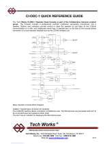
The diagram in Figure 2 illustrates a Model 4010 Radio Dispatch Console configured with
four radio channels. A console can be configured with up to 12 radio channels.

Introduction
10 025-9227S
Figure 2: Typical Model 4010 System Layout
Figure 3: Model 4010R
The Model 4010R Radio Dispatch Console has the same functions and capabilities as the
desktop Model 4010. Whereas the Model 4010 is a desktop console, the Model 4010R is a
rackmount console designed to be mounted into a rack or furniture with a built-in rack
mount compatible system.
In this manual both the Model 4010 and 4010R are referred to as the Model 4010 unless
specifically stated otherwise.
RADIO
D
RADIO
C
RADIO
B
RADIO
A
Model 4010
Radio
Dispatch
Console
Telephone Style
25 Pair Cable,
10 Feet Long
Channel
Punch-Down
Block

11
Manuals
Figure 4: Model 4115B
The Model 4115B Console Expander is a rackmount 60-button panel used to expand the
number of programmable keys available to the Model 4010 and Model 4010R.
Manuals
Several manuals describe the operation, installation, service, and programming of the
Model 4010. This manual describes the installation of the Model 4010. Below is a list of
the manuals and a description of their contents.
Manual Title Part
Number Description
Operator Manual 025-9226 Presents an overview of the console panels, a
description of the functions of each button, and a
detailed description of the Model 4010.
Installation and
Programming Manual
025-9227 Presents a description of how to install, configure, and
program the Model 4010 console and accessories.

Introduction
12 025-9227S
Specifications
Transmit Electrical Specifications
Receive Electrical Specifications
Other Electrical Specifications
Audio Output +10 dBm max. into 600Ω line
Output Impedance Transmit: 600Ω balanced
Idle: 600Ω or 3500Ω
Distortion <2% at full output
Signal-to-Noise > 50 dB
Hum, Cross-Talk all -50 dB at full output
Microphone Input -65 dBm for full output
Headset Input -20 dBm for full output
Page/Spare Input -15 dBm, not compressed
Freq. Response -3 to +1 dB from 250-5000 Hz
Compression Input level increase of 30 dB above knee of compression causes <3 dB output
increase
Input Impedance 600Ω or 10KΩ (4-wire)/3500Ω (2-wire)
Line Balance 66 dB at 1000 Hz
Rx Sensitivity -30 dBm max at knee of compression; adjustable
Freq. Response -3 to +1 dB from 250-5000 Hz (except GT notch)
Compression Input level increase of 30 dB above the knee of compression causes <3 dB output
increase
Distortion < 2%
Call Light Sensitivity -20 dB below knee of compression
Audio Output 5 watts each speaker
Mute Adjustable to -28 dB (with Individual Volume Control Option) or full mute. Mute
time 1 sec to indefinite
Radio Control Local, E & M, Tone Remote, DC Remote
Radio Channels 2-wire simplex/half-duplex or 4-wire half/full duplex
DC Control Operable up to 8KΩ loop resistance
Current programmable 15 mA max in 2.5 mA increments
Accuracy +/-0.25 mA

13
Specifications
Console Power Requirements
Power Supply (802-0092) Specifications
Physical Specifications
Tone Control 15 standard tones supported
programmable (no trimmer adjustment) 650 to 2050 Hz
High Level Guard Tone duration 120/600 mSec
Function Tone Duration 40 mSec
Guard Tone Frequency 2175 Hz
Tone frequency accuracy +/- 0.2%; timing accuracy +/-1.0%
Local Control PTT normally open relay contact rated 1.0 A at 24 VAC/DC
E & M Control TX control via PTT relay, external 48V required
Busy Channel Detect Local Cross-Busy detection
Guard Tone or DC Control detection (LOTL) optional
Recorder Outputs 1 per channel (TX/RX audio summation), plus 1 output per console (various
combinations of select, unselect and microphone audio)
0 dBm level, 600Ω, single-ended outputs
Capacity 12 radio channels plus 1 or 2 phone lines with an optional phone patch card
Operating Temp. +5° to +50° Celsius
Voltage +13.5 VDC (+11.5 VDC minimum — +16.0 VDC maximum)
Current 2.5 amperes maximum
Voltage +13.5 VDC ± 0.5 volts
Current 7 amperes
AC Input 95 to 250 VAC, 47 to 63 Hz
Approval CE
Model 4010
Size height = 9″ x width = 18″ x depth = 14″ inches
Weight 15 pounds
Model 4010R
Size height = 10.5″ x width = 19″ x depth = 10.5″ inches
Weight 15 pounds
Model 4115B
Size height = 5.25″ x width = 19″ x depth = 2.25″ inches
Weight 4 pounds

Introduction
14 025-9227S
Overview
System Description
The Model 4010 Radio Dispatch Console is a single position unit that has many built-in
features. The Model 4010 is a desktop unit, and the Model 4010R is a rackmount unit.
Both units have identical features and capabilities and are referred to as the Model 4010 in
this manual unless specifically stated otherwise. Up to three positions may be paralleled
for multioperator applications with fairly simple wiring. If more positions are necessary,
contact Zetron Technical Support.
The console has individual channel volume, clock and volume meter, all-mute,
simulselect, alerts, site intercom, instant transmit, and individual channel frequency/PL
select. The unit can be configured between 2 and 12 channels in increments of two
channels. The console is self-contained and interfaces directly to base station or repeater
wire lines.
The Model 4010 has a built-in paging encoder which is capable of generating all popular
signaling formats, including: Motorola/GE Two-Tone, and DTMF. Rotary Dial (1500 Hz
or 2805 Hz), Plectron, Quick-Call 1 (2+2), and 5/6 Tone Sequential are available as an
option with Extended Call Paging. With the Instant Call Paging option, these tones can be
automatically routed to the proper channel. Without this option, the tones must be
manually routed. This Instant Call Paging option also allows individual control buttons to
be programmed to send one or an entire sequence of pages.
Each channel can be optioned to support a mix of control types: DC remote, tone remote,
local control, and E&M control. The DC remote control requires one optional DC Control
Daughter Board per DC channel. This DC Control Daughter Board also has a line-
operated transmit light (LOTL) to show if a channel is in use via another source. The tone
remote control requires one optional Tone Remote System Adapter Board per system.
Each channel that requires tone control can now be configured with the channel option
jumpers. If a channel requires LOTL indication, a Tone Remote LOTL Daughter Board is
then added for that specific channel.
A Phone Patch Card is an option that allows the console operator to establish a patch
between any radio channel and a telephone line. The card can have either one or two
telephone interfaces. The console can also function as a hands-free, single-line or dual-line
telephone, giving the operator the ability to receive and place telephone calls from the
console. Only one card can be added per system. It does not require one of the dual
channel slots.
The Expanded Auxiliary I/O Card adds input and output capabilities over the standard 8
inputs and 8 outputs available. This card does require one of the Dual Channel Card slots.
The Model 4115B is a rackmount panel, which allows the system to be configured with an
additional 60 programmable switches. The system can accept a maximum of two
expansion panels. The Console Programming System (CPSW) is used to define the
function of the additional panel(s).

15
Overview
The console can be configured with a variety of communication options. The standard
options are desk microphone, gooseneck microphone, or PTT handset with cradle, and/or
headset. A PTT footswitch is also available to control transmissions.
Installation Sequence
Prior to installation, you are encouraged to review this manual as well as the Operator’s
Manual. This will help your understanding of the system and will ease the installation.
This manual is laid out section-by-section, in the sequence in which the system should be
installed. If you should need help during installation, call Zetron.
Planning
Installation begins with planning the system layout. It is best to consider carefully
the placement of the console and its options, the wiring to a punch-down block,
and to the radios. The channel I/O connectors are laid out with four channels per
the 50 pin Amphenol-type connector and one punch-down block is required per
four channels.
Mapping
Card-slot mapping allocates a particular channel and console card slot to your base
stations. It also creates a cross-reference between the channel and position names
that you are familiar with. After the card-slots have been mapped, the channel and
console should be configured using their various jumpers and switches.
Wiring
After the system has been configured, then wiring of the system may begin. The
system will require wiring between the Console and any punch-down block, the
radio base station, and between the consoles and their various accessory options
(microphones, recorders, encoders, etc.).
Testing
When planning, mounting, configuring, and wiring have been completed, the
system is ready for its first installed test. The components have been tested at the
Zetron factory, but it is necessary for you to perform a preliminary system check in
order to verify the proper configuring and wiring.
Level Setting
The last step is to adjust the audio levels in the system. Adjustments must be per-
formed for the receive and transmit audio levels at every channel, and audio levels
within the console.

Introduction
16 025-9227S
Operation
During its initial operation, the system will operate according to the programming
done at the Zetron factory. If you wish to alter operation through programming, see
Programming on page 79. Changes in the programming may be performed by you
once the system is installed.

Overview
17
Console Installation
Overview
The Model 4010 Communication Console is a self-contained unit, which makes for an
easy installation. Accessories may be added to the console including headset jack box,
desk microphone, handset (desktop unit only), gooseneck microphone, footswitch, and
telephone/radio headset interface. The handset and gooseneck microphone options are
installed at the factory if ordered with the console. They are also an easily added option if
ordered later. Instructions for installing options are included in the following chapter,
Option Installation on page 47.
Major sections in this chapter:
•Important Notes on page 18
•Physical Installation on page 18
•Power on page 19
•System Grounding on page 20
•Slot Mapping on page 21
•Configuring Dispatch Consoles on page 24
•Configuring Dual Channel Cards on page 26
•Wiring to the Channels on page 31
•Split 50 66m Type Punch-Down Block on page 35
•Inputs and Outputs on page 37
•Outputs on page 38
•Auxiliary Audio on page 39
•Labeling on page 39
•Model 4115B Connections on page 40
•Preliminary System Check on page 41
•Level Adjustments on page 42

Console Installation
18 025-9227S
Important Notes
New Units
The Model 4010 Communication Console you have received is fully functional and
calibrated to a factory standard of 0 dBm for both RX and TX levels. The line terminations
are set at low impedance (600 Ω). You will need to reset RX and TX levels for the radio
types and wiring configuration at each site.
It is important to set the impedance of the audio lines to high when connecting the channel
card audio lines in parallel with another 4010 system or remote unit. One device remains
at low impedance (600 ohm) and the remainder are set to high. See Configuring Dual
Channel Cards on page 26 for setting the termination jumpers.
Program/Run Switch
The Model 4010 is programmed by sending a configuration file to it from a PC over a
temporary serial connection. The configuration data is stored in write-protected memory,
so writing must first be enabled by the program/run switch located on the bottom of the
unit. Do not move this switch unless programming or checking the options in the 4010. On
a desktop Model 4010, this switch is located on the bottom of the unit. The "normal" or
"run" switch position is to the right (towards the Unselect speaker). Detailed programming
instructions are provided in Programming on page 79.
Physical Installation
Console Location
When preparing to place the control panels, consider the amount of tabletop space
required not only for the console, but also for a writing surface for the operator. Also,
consider where accessory items such as microphones, foot switches, and headset jack-
boxes may be placed. Another consideration is how close the placement will be to a power
outlet. A solid earth ground must be provided.
Console Access
The channel connectors of the Model 4010 Console and option wiring are accessed from
the rear of the unit. Routing of the channel wires to the common connector block must be
considered. The rear of the unit also has the channel status lights, which need to be
monitored during system verification and troubleshooting. To gain access to insert channel
cards or to make channel or console adjustments, the top of the desktop console is opened
in a clamshell fashion that requires about 17 inches of vertical space. A service loop on the

19
Power
wiring may be necessary for ease of access. The rack-mount console requires the removal
of two screws that hold the top cover on. Access to the cards is then from the top of the
unit and probably requires the unit to be removed from the rack or furniture enclosure.
Power
Primary Power
The Model 4010 requires an external 2.5 Ampere, 13.5 VDC regulated supply. The
minimum input voltage of the console is 11.5 VDC and maximum of 15 VDC. Zetron P/N
802-0092 provides 7 Amps, 13.5 VDC ± 0.5 volts, with a DIN connector to mate with the
input power connector J5. The module operates with an input of 95 to 250 VAC, 47 to 63
Hz, and is UL, CSA, VDE, and CE approved. The pin connections are as follows:
The console is equipped with an internal fuse. This is labeled F1 on the Control Board
near the input power connect J5. The fuse is accessible by lifting the top cover of the unit.
If replacement is required, replace only with 2.5-ampere, slow-blow AGC-type fuse.
Auxiliary Power
A connection for auxiliary power is also provided internal to the unit. Screw terminal
connector J16 is used to connect +12 VDC and ground. The specifications for the auxiliary
DC voltage is the same as the main supply, however the voltage level must not exceed the
main supply by more than 2.5 VDC or drain on the auxiliary supply may occur. The
auxiliary supply is automatically connected when the primary voltage drops more than 3.5
VDC below the voltage of the auxiliary supply.
Connection to the auxiliary is made through the wiring access hole in the back of the unit.
The three-position screw terminal strip J16 is used for connection and AWG #18 stranded
J5 PIN SIGNAL
1PWR-
2 Open
3PWR+
4PWR-
5PWR+
Shell Chassis GND

Console Installation
20 025-9227S
wire is recommended. Strip the ends of the wire back 0.25 inches and insert into J16 and
secure by screwing down the terminal. The pin connections are as follows:
System Grounding
Proper earth grounding is an important electrical consideration. The earth ground protects
the system and personnel from lightning strikes, provides a path for any electrostatic
discharge (ESD), and provides a solid reference for the system. Improper grounding of the
system could cause susceptibility to ESD, induced noise from input power wiring, and
reduced effectiveness of lightning protection devices. Induced noise could cause false
signal indications or a variety of system errors.
A “star” grounding system (a single point ground to which satellite grounds are
connected) is the best grounding system. The central star point must be firmly attached to
a low-impedance earth ground point, such as a ground rod.
If protective punch-down blocks are used, a large diameter (6-gauge) copper conductor (or
equivalent braided strap/ bus bar) must be connected between the ground lug of each block
and the earth ground or central star grounding point. With the protected punch-down
blocks, it is best to wire directly to the earth ground if possible. Each piece of equipment
should have its chassis grounded to the central star point with a separate ground wire. The
gauge of the wire depends on the length of the run, 12 gauge is adequate if the length is
less than 15 feet. The length of the runs should be minimized. Securely connect a
grounding wire to the case of each unit making sure that a metal-to-metal connection is
made (no paint or oxidation layer). Most Zetron equipment provides a grounding stud.
Figure 5 shows a central star grounding system.
All earth grounds in the system should be isolated from signal lines. It is easy to couple
ESD or lightning noise spikes if these lines run parallel for any distance. The AC power
J16 PIN Location SIGNAL
1 Nearest to channel card slot PWR+
2 Center terminal PWR-
3 Nearest to side of case PWR-
Warning! Improper system grounding can cause electric shock to
personnel, damage to equipment, and system malfunctions.
STOP
/