Page is loading ...

Mounting kits PR 6145/00N, PR 6145/00S, PR 6145/08N, PR 6145/10N
Installation Manual
Translation of the Original Installation Manual 9499 053 25700 Edition 7.5.0 12/15/2022
Minebea Intec GmbH, Meiendorfer Str. 205 A, 22145 Hamburg, Germany
Phone: +49.40.67960.303 Fax: +49.40.67960.383

Foreword
Must be followed!
Any information in this document is subject to change without notice and does not represent a commitment on
the part of Minebea Intec unless legally prescribed. This product should only be operated/installed by trained
and qualified personnel. In correspondence concerning this product, the type, name, and release number/serial
number as well as all license numbers relating to the product have to be cited.
Note
This document is partially protected by copyright. It may not be changed or copied, and it may not be used
without purchasing or written permission from the copyright owner (Minebea Intec). The use of this product
constitutes acceptance by you of the abovementioned provisions.

Table of contents
1 Introduction......................................................................................................................................... 3
1.1 Read the manual......................................................................................................................................................... 3
1.2 This is what operating instructions look like .......................................................................................................... 3
1.3 This is what lists look like........................................................................................................................................... 3
1.4 This is what menu items and softkeys look like..................................................................................................... 3
1.5 This is what the safety instructions look like.......................................................................................................... 3
1.6 Hotline.......................................................................................................................................................................... 4
2 Safety instructions...............................................................................................................................5
2.1 General notes .............................................................................................................................................................. 5
2.2 Intended use................................................................................................................................................................ 5
2.3 Initial inspection.......................................................................................................................................................... 5
2.4 Before operational startup........................................................................................................................................ 5
3 Recommendations for installation .......................................................................................................6
3.1 Load cell and constrainer arrangement..................................................................................................................6
4 Specifications ......................................................................................................................................8
4.1 Equipment supplied...................................................................................................................................................8
4.1.1 PR 6145/00, PR 6145/08, PR 6145/10 .........................................................................................................8
4.2 Dimensions .................................................................................................................................................................. 9
4.2.1 Hole patterns .................................................................................................................................................... 9
4.3 Technical data ........................................................................................................................................................... 10
5 Installation.......................................................................................................................................... 11
5.1 Prior to mounting ...................................................................................................................................................... 11
5.1.1 Preparing the foundation/substructure ..................................................................................................... 11
5.2 Tightening torques.................................................................................................................................................... 11
5.3 Assembly.....................................................................................................................................................................12
5.3.1 Safety instructions ..........................................................................................................................................12
5.3.2 Installing the mounting kit ............................................................................................................................12
5.4 Check mounting.........................................................................................................................................................15
6 Cleaning............................................................................................................................................. 16
7 Disposal ..............................................................................................................................................17
8 Spare parts and accessories ............................................................................................................... 18
8.1 Replacement parts ................................................................................................................................................... 18
8.2 Accessories ................................................................................................................................................................ 18
8.2.1 Load discs........................................................................................................................................................ 18
9 Certificates ........................................................................................................................................ 19
Mounting kits PR 6145/00N, PR 6145/00S, PR 6145/08N, PR 6145/10N Table of contents
Minebea Intec EN-1

9.1 CE-PR 6145 ................................................................................................................................................................20
9.2 004/2021 ....................................................................................................................................................................21
9.3 2451-CPR-EN1090-2014.2089.005 ...................................................................................................................... 23
Mounting kits PR 6145/00N, PR 6145/00S, PR 6145/08N, PR 6145/10N Table of contents
EN-2 Minebea Intec

1 Introduction
1.1 Read the manual
-Please read this manual carefully and completely before using the product.
-This manual is part of the product. Keep it in a safe and easily accessible location.
1.2 This is what operating instructions look like
1. - n. are placed before steps that must be done in sequence.
1.3 This is what lists look like
-indicates an item in a list.
1.4 This is what menu items and softkeys look like
[ ] frame menu items and softkeys.
Example:
[Start]- [Applications]- [Excel]
1.5 This is what the safety instructions look like
Signal words indicate the severity of the danger involved when measures for preventing
hazards are not followed.
DANGER
Warning of personal injury
DANGER indicates death or severe, irreversible personal injury which will occur if the
corresponding safety measures are not observed.
Take the corresponding safety precautions.
WARNING
Warning of hazardous area and/or personal injury
WARNING indicates that death or severe, irreversible injury may occur if appropriate
safety measures are not observed.
Take the corresponding safety precautions.
CAUTION
Warning of personal injury.
CAUTION indicates that minor, reversible injury may occur if appropriate safety
measures are not observed.
Take the corresponding safety precautions.
is placed before a step.
describes the result of a step.
1 Introduction Mounting kits PR 6145/00N, PR 6145/00S, PR 6145/08N, PR 6145/10N
Minebea Intec EN-3

NOTICE
Warning of damage to property and/or the environment.
NOTICE indicates that damage to property and/or the environment may occur if
appropriate safety measures are not observed.
Take the corresponding safety precautions.
Note:
User tips, useful information, and notes.
1.6 Hotline
Phone: +49.40.67960.444
Fax: +49.40.67960.474
eMail: [email protected]
Mounting kits PR 6145/00N, PR 6145/00S, PR 6145/08N, PR 6145/10N 1 Introduction
EN-4 Minebea Intec

2 Safety instructions
2.1 General notes
NOTICE
Warning of damage to property and/or the environment.
The product was in perfect condition with regard to safety features when it left the
factory.
To maintain this condition and to ensure safe operation, the user must follow the
instructions and observe the warnings in this manual.
2.2 Intended use
The mounting kits PR 6145/00N, PR 6145/00S, PR 6145/08N, PR 6145/10N are intended
for weighing tasks, and must only be used as such.
The mounting kits PR 6145/00N, PR 6145/00S, PR 6145/08N, PR 6145/10N are designed
for installing the load cells PR 6201, PR 6203, PR 6204.
The dimensions of all mounting and structural components must be calculated so that
sufficient overload capacity is ensured for all loads which may occur while taking the
relevant standards into account. In particular, upright weighing objects must be
safeguarded against the weighing installation turning over or being shifted, thus
eliminating danger to people, animals, or goods even in the case of a break in a load cell
or mounting element.
Installation and repair work must only be carried out by expert/qualified personnel.
The mounting kits reflect the state of the art. The manufacturer does not accept any
liability for damage caused by third-party system components or due to incorrect use of
the product.
2.3 Initial inspection
Check the contents of the consignment for completeness. Check the contents visually to
determine whether any damage has occurred during transport. If there are grounds for
rejection of the goods, a claim must be filed with the carrier immediately. The
Minebea Intec sales or service organization must also be notified.
2.4 Before operational startup
NOTICE
Perform visual inspection.
Before operational startup as well as after storage or transport, inspect the
mounting kit visually for signs of mechanical damage.
2 Safety instructions Mounting kits PR 6145/00N, PR 6145/00S, PR 6145/08N, PR 6145/10N
Minebea Intec EN-5

3 Recommendations for installation
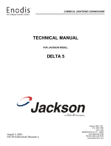
3.1 Load cell and constrainer arrangement
Examples:
Key
Do not constrain this position.
Constrainer
Load application
Possible direction of movement
Mounting kits PR 6145/00N, PR 6145/00S, PR 6145/08N, PR 6145/10N 3 Recommendations for installation
EN-6 Minebea Intec

-To ensure the required free moving space of the weighing facility, a maximum of
3 mounting kits with constrainer may be used to constrain a weighing object.
Round containers are the exception (image ① and ②). In this case, any number of
constrainers can be installed, provided that they are tangentially aligned.
Special mounting kits are available for weighing points without constrainers.
Alternatively, the constrainer can simply be removed.
With elastic constructions, it may be necessary to deviate from this recommendation
in order to guarantee the weighing object has sufficient stability.
3 Recommendations for installation Mounting kits PR 6145/00N, PR 6145/00S, PR 6145/08N, PR 6145/10N
Minebea Intec EN-7

4 Specifications
4.1 Equipment supplied
4.1.1 PR 6145/00, PR 6145/08, PR 6145/10
1
2
3
4
5
6
7
No. Description
1 Lower plate
2 Centering device (3× pin)
3Only for PR 6145/00S for 0.5 to 10 t:
Lower load disc
(order no. for 20 to 75 t, see Chapter 8.1)
4Only for PR 6145/00S for 0.5 to 10 t:
Supporting ring
(order no. for 20 to 300 t see Chapter 8.1)
5 Upper load disc
6 Upper plate
7 Screw (2×) and spring washer (2×) for the equipotential bonding cable
(supplied with the load cell)
8 Quick guide (not shown)
Mounting kits PR 6145/00N, PR 6145/00S, PR 6145/08N, PR 6145/10N 4 Specifications
EN-8 Minebea Intec

4.2 Dimensions
4.2.1 Hole patterns
A
BB
A
f
g
hg
h
d
e
M10
k
l f
e
d
M10
b
i
ca
All dimensions in mm
Mounting kit a b c d e f g h j k l
PR 6145/00N+S 15 190.5 15 150 115 14 65 100 18 9 61.5
PR 6145/08N 30 290.0 30 180 145 18 95 130 18 22 86.5
PR 6145/10N 40 385.0 40 220 185 24 135 180 14 28 109.5
4 Specifications Mounting kits PR 6145/00N, PR 6145/00S, PR 6145/08N, PR 6145/10N
Minebea Intec EN-9

4.3 Technical data
Mounting kit PR 6145/00N PR 6145/00S PR 6145/08N PR 6145/10N
Max. capacity of load cell 500 kg…75 t 500 kg…75 t 100 t 200 t, 300 t
Permissible temperature range -40 °C…+100 °C -40 °C…+100 °C -40 °C…+100 °C -40 °C…+100 °C
Material * ** * *
Weight net/gross 4.00 kg/4.50 kg 4.67 kg/5.16 kg 12.1 kg/12.5 kg 27.1 kg/27.4 kg
* Steel galvanized, chromated and sealed (ROHS-compliant)
** Stainless steel 1.4301 acc. to DIN EN 10088-3
Mounting kits PR 6145/00N, PR 6145/00S, PR 6145/08N, PR 6145/10N 4 Specifications
EN-10 Minebea Intec

5 Installation
5.1 Prior to mounting
5.1.1 Preparing the foundation/substructure
-The foundation for the mounting kit must be horizontal (use spirit level), flat, and
rigid for the intended loads.
-The load distribution on the available load cells must be as even as possible to
prevent overload of the individual load cells.
-The substructure foundations/supporting surfaces for the mounting kits should be at
the same level, and the supporting surfaces of the weighing object (e.g. vessel feet)
must be arranged in parallel.
-If soft filler layers (e.g. made from rubber or plastic material) are used between the
mounting kit and vessel/or between the mounting kit and substructure for vibration
dampening or for temperature insulation, a load compensating plate must be
provided between this soft filler layer and the mounting kit to ensure even load
application into the mounting kit.
The design of the insulation and compensation plates depends on the respective
application.
5.2 Tightening torques
The corresponding tightening torques are given in the following table.
Mounting kit Thread Washer Tightening torque
PR 6145/00N M12-8.8 * 85 Nm
PR 6145/00S M12-A2-70 * 60 Nm
PR 6145/08N M16-8.8 ** 210 Nm
PR 6145/10N M20-8.8 *** 300 Nm
*
Recommendation for the washers of
M12 mounting screws:
DIN 7349 (d = 30, h = 6) or DIN 9021 or ISO 7093-2
(d = 37, h = 3)
**
Recommendation for the washers of
M16 mounting screws:
DIN 7349 (d = 40, h = 6) or ISO 7093 (d = 50, h = 3)
***
Recommendation for the washers of
M20 mounting screws:
DIN 7349 (d = 44, h = 8) or ISO 7093 (d = 60, h = 4)
5 Installation Mounting kits PR 6145/00N, PR 6145/00S, PR 6145/08N, PR 6145/10N
Minebea Intec EN-11

5.3 Assembly
5.3.1 Safety instructions
WARNING
The vessel may turn over during mounting.
Securing the vessel against tipping is imperative.
Use an appropriate lifting jack.
NOTICE
Welding or lightning strike current flowing through the cell can damage it.
All electrical welding on the weighing system must be finished before mounting the load
cells.
When installing the load cell, immediately bypass the load cell with a flexible copper
strap (included in the load cell equipment).
During any additional electrical welding work near the load cell:
-Disconnect the load cell cables.
-Bypass the load cell using the flexible copper strap.
-Make sure that the grounding clamp of the welding set is fitted as closely as possible
to the welding joint.
5.3.2 Installing the mounting kit
Note:
Screw mounting of the upper and lower plates is described below.
The work steps must be carried out on all support points of the vessel.
Requirements:
-All threaded holes for the lower plate are available in the foundation/substructure
(see Chapter 4.2.1).
-All threaded holes for the upper plate are available in the vessel bracket/vessel foot
(see Chapter 4.2.1).
Mounting kits PR 6145/00N, PR 6145/00S, PR 6145/08N, PR 6145/10N 5 Installation
EN-12 Minebea Intec

1 2 3 4
5
6
7810 91112
Procedure:
For PR 6145/00S only:
Note:
When installing 20 to 75 t load cells, the lower load disc must be used with
supporting ring PR 6143/54S; for order no. see Chapter 8.1.
1. Screw the lower plate (8) to the foundation (7) and screw the upper plate (3) to the
weighing object support (1). The property classes and tightening torques of the
screws (2 and 12) must be observed; see Chapter 5.2. Ensure that the plates are
parallel and seated vertically above each other.
2. Connect an equipotential bonding conductor (5) (supplied with the load cell) between
the upper and lower plates.
3. Clean the load cell base on the lower plate (8) and the recess for the upper load
disc (4) in the upper plate (3).
4. Apply sufficient grease to the contact surfaces between load cell/load disc and upper
plate/load disc.
5. Insert the load cell (6) with lower load disc (10) and supporting ring (11) (supplied with
the load cell) vertically in the centering device (9) on the lower plate (8).
5 Installation Mounting kits PR 6145/00N, PR 6145/00S, PR 6145/08N, PR 6145/10N
Minebea Intec EN-13

Insert the load cell (6) with the lower load disc (10) marked "SS" and the associated
food-safe supporting ring (11) (light beige) vertically in the centering device (9) on the
lower plate (8).
Note:
Stainless steel load discs are marked with a double groove.
The following images show a schematic representation of the load cell and upper
load disc.
Small load cell radius (15 mm) Large load cell radius (35 mm)
Emax = 500 kg to 10 t Emax = 20 to 75 t
Ensure the upper load disc is in the correct position – see image.
It is essential to ensure that the load cell is inserted in the mounting kit vertically and
without being canted.
6. Carefully lower the vessel to insert the upper load disc (4) into the recess of the upper
plate (3) and to position it on the load cell (6).
Mounting kits PR 6145/00N, PR 6145/00S, PR 6145/08N, PR 6145/10N 5 Installation
EN-14 Minebea Intec

5.4 Check mounting
When all mounting kits have been installed, check them for proper mounting.
In particular, force shunts should be avoided.
It is essential to check:
-whether the load cell has been inserted in the mounting kit vertically and without
being canted.
If necessary, loosen the screws in the upper and lower plates slightly and move the
plates.
-whether the upper and lower plates are mounted in a horizontal position.
-whether free moving space and the required play for thermal expansion are provided.
The free moving space which is required for displacement of the measured object due to
thermal expansion, vibration, etc. can be utilized without reducing the measuring
accuracy only if the load cell has been installed exactly.
To avoid force shunts, all incoming and outgoing lines (hoses, pipes, cables) must be
connected to the measured object with the greatest flexibility possible.
The entire load must be supported by the load cells!
5 Installation Mounting kits PR 6145/00N, PR 6145/00S, PR 6145/08N, PR 6145/10N
Minebea Intec EN-15

6 Cleaning
The mounting kit is easy to clean. It can be spray-washed with water.
For this purpose, spray the water jet from top to bottom and around the mounting kit.
NOTICE
Some cleaning agents may not be compatible with the mounting kit material.
When using cleaning agents, ensure that their compatibility with the mounting kit
material has been tested and approved (see Chapter 4.3).
Mounting kits PR 6145/00N, PR 6145/00S, PR 6145/08N, PR 6145/10N 6 Cleaning
EN-16 Minebea Intec

7 Disposal
Our products and their packaging should not be disposed of in municipal waste (e.g.
garbage can for recyclable packaging, garbage can for paper packaging, etc.). They can
either be recycled by the customer themselves, providing this complies with
requirements set out by electrical or electronic waste or packaging waste laws, or sent
back to Minebea Intec at a charge.
This option of returning the product is intended to provide proper recycling or reuse in a
manner that is collected separately from municipal waste.
Before disposing of or scrapping the old products, any single-use or rechargeable
batteries should be removed and taken to a suitable collection point. The type of battery
used is specified in the technical data.
Please see our General Terms and Conditions for further information.
Service addresses for repair acceptance and collection points can be found on the
product information enclosed with the product as well as on our website (www.minebea-
intec.com).
Should you have any further questions, please contact your local service representative or
our service center.
Minebea Intec GmbH
Repair center
Meiendorfer Strasse 205 A
22145 Hamburg, Germany
Phone: +49.40.67960.333
We reserve the right not to accept products that are contaminated with hazardous
substances (ABC contamination).
7 Disposal Mounting kits PR 6145/00N, PR 6145/00S, PR 6145/08N, PR 6145/10N
Minebea Intec EN-17

8 Spare parts and accessories
8.1 Replacement parts
No. Description Max. capacity Order no.
1 Upper load disc (for PR 6145/08N) 100 t 5322 520 10552
2 Upper load disc (for PR 6145/10N) 200 t, 300 t 5322 520 10553
3 Flexible copper strap, 400 mm long 5312 321 28057
N = steel zinc plated, passivated and sealed (RoHS-compliant)
8.2 Accessories
8.2.1 Load discs
To install the load cell, the following load discs are recommended:
No. Description Max. capacity Order no.
1 Upper load disc, standard PR 6143/50N 500 kg–75 t 9405 361 43501
2 Upper load disc, PR 6143/50S 500 kg–75 t 9405 361 43502
3 Lower load disc with supporting ring PR 6143/24S 500 kg–10 t 9405 361 43242
4 Lower load disc with supporting ring PR 6143/54S 20–75 t 9405 361 43542
N = steel zinc plated, passivated and sealed (RoHS-compliant)
S = stainless steel
Mounting kits PR 6145/00N, PR 6145/00S, PR 6145/08N, PR 6145/10N 8 Spare parts and accessories
EN-18 Minebea Intec
/