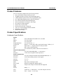
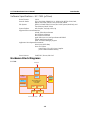
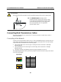
Moxa UC-7101 is a mini, RISC-based embedded computer designed for communication applications. It features an ARM9 processor, 16MB RAM, 8MB Flash ROM, and one 10/100 Mbps Ethernet port. The UC-7101 also has one software-selectable RS-232/422/485 serial port, a built-in SD socket for storage expansion, and a real-time clock. It runs on a μClinux operating system and is suitable for data acquisition and protocol conversion applications.
Moxa UC-7101 is a mini, RISC-based embedded computer designed for communication applications. It features an ARM9 processor, 16MB RAM, 8MB Flash ROM, and one 10/100 Mbps Ethernet port. The UC-7101 also has one software-selectable RS-232/422/485 serial port, a built-in SD socket for storage expansion, and a real-time clock. It runs on a μClinux operating system and is suitable for data acquisition and protocol conversion applications.


-
 1
1
-
 2
2
-
 3
3
-
 4
4
-
 5
5
-
 6
6
-
 7
7
-
 8
8
-
 9
9
-
 10
10
-
 11
11
-
 12
12
-
 13
13
-
 14
14
-
 15
15
-
 16
16
-
 17
17
-
 18
18


Moxa UC-7101 is a mini, RISC-based embedded computer designed for communication applications. It features an ARM9 processor, 16MB RAM, 8MB Flash ROM, and one 10/100 Mbps Ethernet port. The UC-7101 also has one software-selectable RS-232/422/485 serial port, a built-in SD socket for storage expansion, and a real-time clock. It runs on a μClinux operating system and is suitable for data acquisition and protocol conversion applications.
Ask a question and I''ll find the answer in the document
Finding information in a document is now easier with AI
Related papers
-
Moxa Technologies UC-7101 User manual
-
Moxa UC-7100 Series Quick setup guide
-
-
Moxa EM-2260 Series Quick setup guide
-
-
-
Moxa EM-1220-T-LX User manual
-
-
-
 Moxa Technologies EM-1220 Series User manual

Other documents
-
Nortel Networks 1002rp User manual
-
-
Nortel Networks CALLPILOT 555-7101-226 User manual
-
-
-
 Moxa Technologies EM-1240-LX User manual
-
-
Nortel Networks CALLPILOT 555-7101-217 User manual
-
 Actuator Systems ACT-NBDB-3PBEZ Operating instructions
-
 Acorn Safety S1320-BF Installation, Operation And Maintenance Instructions


